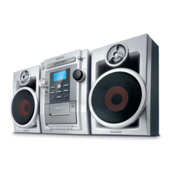
Philips FWM139 Service Manual
Mini system
Hide thumbs
Also See for FWM139:
- Quick start manual (3 pages) ,
- Specifications (2 pages) ,
- User manual (22 pages)
Table of Contents
Advertisement
Mini System
TABLE OF CONTENTS
Handling chip components ............................................................ 1-1
Service tools .................................................................................. 1-1
Leadfree and safety information ................................................... 1-2
Technical specification .................................................................. 2-1
Service measurement setup ......................................................... 2-2
Connections and controls ..................................................... 3-1...3-2
Set block diagram ......................................................................... 5-1
Set wiring diagram ........................................................................ 5-2
Circuit Diagram (part 1)
Circuit diagram (CPU / Display board) ..................................... 6-1
Circuit diagram (AMP / Power board) ...................................... 6-2
Top view .................................................................................. 6-3
Bottom view .............................................................................. 6-4
©
Copyright 2006 Philips Consumer Electronics B.V. Eindhoven, The Netherlands
All rights reserved. No part of this publication may be reproduced, stored in a retrieval
system or transmitted, in any form or by any means, electronic, mechanical, photocopying,
or otherwise without the prior permission of Philips.
Published by YT 0627 Service Audio.
Version 1.0
Subject to modification
FWM139, MAS339
Circuit Diagram (part 2)
Circuit diagram - Cassette part ................................................ 7-1
Circuit diagram - CD/MP3 part ................................................. 7-2
Circuit diagram - Tuner/Audio part ........................................... 7-3
Top view .................................................................................. 8-1
Bottom view .............................................................................. 8-2
Exploded view diagram ................................................................. 9-1
Accessories and Mechanical partslist ........................................... 9-2
Electrical partslist .............................................................. 10-1...10-3
all versions
© 3141 785 31100
Advertisement
Table of Contents

Related Manuals for Philips FWM139


Summary of Contents for Philips FWM139
-
Page 1: Table Of Contents
Bottom view ................6-4 © Copyright 2006 Philips Consumer Electronics B.V. Eindhoven, The Netherlands All rights reserved. No part of this publication may be reproduced, stored in a retrieval system or transmitted, in any form or by any means, electronic, mechanical, photocopying, or otherwise without the prior permission of Philips. -
Page 2: Handling Chip Components
1 - 1 HANDLING CHIP COMPONENTS... - Page 3 1 - 2...
- Page 4 2 - 1 SPECIFICATION GENERAL: AMPLIFIER: Mains voltage /05/12 : 220-240V Output power : 2 x 20 W RMS /55/77/78 : 110-127/220-240V Switchable Speaker impedance : 8 ohm Mains frequency Frequency response Within r 3dB : 63Hz – 16 kHz /05/12 : 50 Hz : 8dB r 3dB at 125Hz /55/77/78 : 50/60 Hz...
-
Page 5: Service Measurement Setup
2 - 2 SERVICE MEASUREMENT Tuner FW Bandpass LF Voltmeter 250Hz-15kHz e.g. PM2534 e.g. 7122 707 48001 RF Generator e.g. PM5326 S/N and distortion meter e.g. Sound Technology ST1700B Use a bandpass filter to eliminate hum (50Hz, 100Hz) and disturbance from the pilottone (19kHz, 38kHz). Tuner AM (MW,LW) Bandpass LF Voltmeter... -
Page 6: Connections And Controls
3 - 1 CONNECTION AND CONTROLS... - Page 7 3 - 2 CONNECTION AND CONTROLS...
-
Page 8: Disassembly Diadrams
4 - 1 DISASSEMBLY DIADRAMS A. Switch on the set. Press OPEN/CLOSE to open the CD Tray. Remove CD Door. B. Remove Top Cabinet B1: Remove screws SP 3x12 - 6 pcs. B2: Remove screws SP 3x12 - 4 pcs. B3: Remove screws SP 3x12 - 4 pcs. - Page 9 4 - 2 4 - 2 DISASSEMBLY DIADRAMS C. Remove CD Loader C1: Remove screws SP 3x12 - 2 pcs. C2: Remove screws SP 3x15 - 2 pcs. C3: Remove screws SP 3x10 - 1 pcs. Remove Key Board Assembly D.
-
Page 10: Set Block Diagram
5 - 1 5 - 1 SET BLOCK DIAGRAM... -
Page 11: Set Wiring Diagram
5 - 2 5 - 2 SET WIRING DIAGRAM... -
Page 12: Circuit Diagram - Cpu Display Board
6 - 1 6 - 1 CIRCUIT DIAGRAM - CPU DISPLAY BOARD... -
Page 13: Circuit Diagram (Amp / Power Board)
6 - 2 6 - 2 CIRCUIT DIAGRAM - AMP / POWER BOARD... -
Page 14: Layout Diagram - Cpu/Display & Amp/Power Boards Top View
6 - 3 6 - 3 LAYOUT DIAGRAM - CPU / DISPLAY & AMP / POWER BOARD (TOP VIEW) -
Page 15: Bottom View
6 - 4 6 - 4 LAYOUT DIAGRAM - LAYOUT DIAGRAM - CPU / DISPLAY & AMP / POWER BOARD (BOTTOM VIEW) -
Page 16: Circuit Diagram - Cassette Part
7 - 1 7 - 1 CIRCUIT DIAGRAM - CASSETTE PART... -
Page 17: Circuit Diagram - Cd/Mp3 Part
7 - 2 7 - 2 CIRCUIT DIAGRAM - CD / MP3 PART... -
Page 18: Circuit Diagram - Tuner/Audio Part
7 - 3 7 - 3 CIRCUIT DIAGRAM - TUNER / AUDIO PART... -
Page 19: Layout Diagram (Main Combi Board) Top View
8 - 1 8 - 1 LAYOUT DIAGRAM - MAIN BOARD (TOP VIEW) - Page 20 8 - 2 8 - 2 LAYOUT DIAGRAM - MAIN BOARD (TOP VIEW)
-
Page 21: Exploded View Diagram
9 - 1 9 - 1 EXPLODED VIEW DIAGRAM... -
Page 22: Mechanical Parts List
9 - 2 ACCESSORIES MAS339 FWM139 9965 000 38845 9965 000 38781 REMOTE HANDSET 9965 000 38846 9965 000 38808 WOODEN SPEAKER BOX 9965 000 38873 AC CORD SET (BS 6500 APP) (FWM139/05) 9940 000 05125 AC CORD SET (VDE APP) -
Page 23: Electrical Partslist
10 - 1 ELECTRICAL PARTS LIST MISCELLANEOUS JK701 9940 000 03989 ST PHONES JACK 3,5MM 7P 9940 000 04779 SPEAKER TERMINAL 4P MSP-124V 9940 000 03993 16 PIN FFC CABLE 210mm P=1.0 T901 9965 000 38824 TRANSFORMER,123V/230V,EI-66 9940 000 04736 VOLTAGE SWITCH MAIN PCB ASSY CF101... - Page 24 10- 2 ELECTRICAL PARTS LIST POWER AMP BOARD ASSY D704 9965 000 38831 DIODE (SB10-05A3) D705 9965 000 38831 DIODE (SB10-05A3) D905 9965 000 38843 BRIDGE RECTIFIER KBU604 6A F901 9940 000 04781 FUSE 50T-032H 3.15A 250V (S.B.) F902 9940 000 04781 FUSE 50T-032H 3.15A 250V (S.B.) F903 9965 000 38821...
- Page 25 10 - 3 ELECTRICAL PARTS LIST MP3/CD BOARD ASSY IC801 9965 000 38871 IC LC78690NW-E IC802 9965 000 38842 IC LA6548NH (4 CH DRIVER) Q801 9940 000 03973 CHIP TR MMBT9015C Q802 9965 000 38840 TR PNP 2SB764-D X801 9965 000 38825 CRYSTAL 16.9344MHZ (HC-49S) SW314 9940 000 04792...
Need help?
Do you have a question about the FWM139 and is the answer not in the manual?
Questions and answers