Table of Contents
Advertisement
Quick Links
REMOTE CONTROL
REMOTE CONTROL
OVERLOAD
OVERLOAD
FRONT CONTROL
FRONT CONTROL
COMMUNICATIONS
COMMUNICATIONS
HEARTBEAT
HEARTBEAT
POWER
POWER
RS-232
RS-232
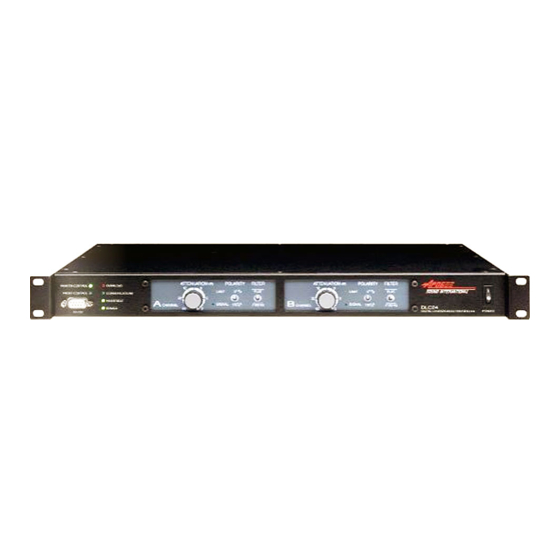
DLC24
Digital Loudspeaker Controller
Installation and Use Manual
ATTENUATION
POLARITY
FILTER
(dB)
12
6
o
LIMIT
0
3
32
A
o
SIGNAL
180
CHANNEL
60
0
ATTENUATION
(dB)
12
6
FLAT
LIMIT
3
32
B
SIGNAL
100 Hz
CHANNEL
60
0
POLARITY
FILTER
o
0
FLAT
o
180
100 Hz
DLC24
DLC24
DIGITAL LOUDSPEAKER CONTROLLER
DIGITAL LOUDSPEAKER CONTROLLER
© 2004 Apogee Sound International
Specifications subject to change without notice.
55-0067-01D 0710 All rights reserved.
www.apogee-sound.com
POWER
POWER
Advertisement
Table of Contents

Summary of Contents for Apogee DLC24
- Page 1 CHANNEL DLC24 DLC24 POWER POWER POWER POWER DIGITAL LOUDSPEAKER CONTROLLER DIGITAL LOUDSPEAKER CONTROLLER RS-232 RS-232 DLC24 Digital Loudspeaker Controller Installation and Use Manual © 2004 Apogee Sound International Specifications subject to change without notice. 55-0067-01D 0710 All rights reserved. www.apogee-sound.com...
- Page 2 Notice: Every effort was made to ensure that the information in this guide was complete and accurate at the time of printing. However, information is subject to change. WARNING: To reduce the risk of Fire or Electric Shock, Do Not Expose this apparatus to rain or moisture.
-
Page 3: Table Of Contents
Delay ........................18 Equalization ......................18 Snapshots ......................19 Resets ........................19 Network Control and Monitoring from Non-Apogee Software and Devices ..19 Hardware Preset ....................19 APPLICATION SETUP & CONFIGURATION EXAMPLES........20-27 Application Setup & Configuration 1: Mono Bi-Amp with AUX-Fed Subwoofer....20-21 Application Setup & Configuration 2: Stereo Bi-Amp ..........22-23 Application Setup &... -
Page 4: Precautions & Safety Notes
Precautions & Safety Notes English • To reduce the risk of electric shock, disconnect the AC main power cord before installing audio cable. Reconnect the power cord only after making all signal connections. • Connect the unit only to a three-pole, three-wire grounding mains receptacle. - Page 5 Precautions & Safety Notes Deutsch (cont’d) • Um die Gefahr eines elektrischen Schlages auf ein Minimum zu reduzieren, den Lautsprecher Kontroller vom Stromnetz trennen, bevor ein Audiosignalkabel angeschlossen wird. Das Netzkabel erst nach Herstellung aller Signalverbindungen wieder einstecken. • Den Kontroller an eine geerdete dreipolige Schuko-Netzsteckdose anschließen.
-
Page 6: Description
The DLC24 is intended to be the last device in the signal chain before the power amplifier(s). It is usually fed signal from a mixing console, although the source may be one of a number of devices such as a tape player, CD player, or equalizer. -
Page 7: Panel Descriptions
DLC24 Front Panel 1. RS-232 Connection Local PC Connection is made via this RS-232 port. 2. Control Indicators Indicates whether the DLC24 Control Selector Switch on the rear panel is set to Front Control or Remote Control. 3. Status Indicators: Overload- LED indicates clipping at any input or output stage. -
Page 8: Dlc24 Rear Panel
1. IEC Inlet 100 – 240V, 1.1A, 50-60 Hz AC power receptacle. 2. Signal Ground Switch Select whether the DLC24’s power supply ground is connected to chassis ground or “lifted”. 3. Control Selector Switch Select Front or Remote Control. 4. Input Selector Switch Select whether the DLC24 accepts analog or digital signals through the XLR inputs. -
Page 9: Connections
TX- from the PC should attach to RX+ and RX- of the DLC24. RX+ Pin 2: TX- Pin 4: RX- FRONT and RX- from the PC should attach to TX+ and TX- of the DLC24. It is INPUT Pin 3: TX+ important to use high-quality, properly shielded cable for this ANALOG application. -
Page 10: Output Signal Connection
REMOTE Second is the Signal Ground lift switch located at the rear of the unit near the AC inlet. This switch “lifts” or “floats” DLC24’s power supply ground with respect to chassis ground. The Input Shield Pin 1 lift and Signal Ground lift switch may be used individually or together. -
Page 11: Operation
Operation Front Panel Controls and Indicators Remote Control Indicator This LED will illuminate green when the DLC24’s Control Selector Switch is in the Remote position. Front panel controls are disabled and only PC control is available. Front Control Indicator This LED will illuminate green when the DLC24’s Control Selector Switch is in the Front position. -
Page 12: Rear Panel Controls And Indicators
DIGITAL Control Selector Switch CONTROL CONTROL RESET When this switch is set to “Front”, the DLC24’s front panel controls are FRONT FRONT active and any associated software controls are inhibited. When the Control INPUT Selector Switch is set to “Remote”, the software controls are active and the ANALOG DLC24’s front panel controls are inhibited. -
Page 13: Software
ADAM. ADAM Software The ADAM Software provides control and monitoring of the DLC24 through a PC, allowing the use of a wide variety of features that would otherwise be unavailable to the user. -
Page 14: Dlc24 Speaker Configuration Software
Polarity may be enabled or disabled. When enabled, the Polarity Switch on the front panel of the DLC24 is active as is the Polarity box in ADAM. When disabled, neither the front panel switch on the DLC24 nor the Polarity box in ADAM are operable. When a subwoofer is selected, such as the AESB, “Enable”... -
Page 15: Dlc24 Speaker Configuration Software
9. Scan Network Select Scan Network to search and detect any units on the network. In order for a DLC24 to be detected, it must be properly connected to a PC using either an RS-232 or RS-422 connection. Refer to PC Interface Connection (page 7) for more information. -
Page 16: Adam Software
Software After having downloaded the Speaker Configuration file to the DLC24, launch the ADAM software. ADAM Software After launching ADAM, select the COM port for the software to access the unit or network. If there are multiple COM ports for dif- ferent zones, all the relevant COM ports may be selected by holding down the CTRL key while selecting the COM ports. -
Page 17: System Design, Preplanning, And Layout
Software System Design, Preplanning, and Layout It is recommended that the system layout be planned in advance so that on-site system setup can be quick and effective. Loudspeakers should be placed into a tree structure consisting of Rooms, Arrays, and Subarrays. The organization of the system at this point will greatly impact how easily the system can be tuned and controlled later. -
Page 18: System Example
Software System Example This system example is provided to efficiently outline how to utilize the system structure of ADAM. It is provided in this manual as a teaching tool and does not exist as a tutorial in the software. It includes a center cluster of two speakers in a horizontal array along with one subwoofer and four front fill speakers mounted at the stage lip. -
Page 19: Speakers
Loudspeaker Status Window Input Clip – This illuminates red when the input clips. DSP Online – This illuminates green when the DLC24 is powered up and the DSP is functioning properly. Out 3/Out 4 – Each output associated with the channel will be shown with corresponding speaker type and passband. -
Page 20: Gain Control
Software Gain Control Gain can be individually set for each channel or can be set for groups of channels at one time. Gain can be adjusted by dragging the fader or by entering data directly into the window labeled “Gain”. Gain must be entered as a negative number. -
Page 21: Adam Software
Network Control and Monitoring from Non-Apogee Software and Devices If controlling the loudspeakers from a non-Apogee device or checking the system using Hyperterminal instead of Apogee software, use the following parameters: Baudrate 38400 • 8-bit • No parity • 1 stop-bit • No hardware handshaking In ASCII setup: Set Echo local character •... -
Page 22: Application Setup & Configuration Examples
RS-422 or RS-232 LEFT AUX 2 (Front) or AUX 1 AUX 2 AUX 2 L or AUX 1 L or AUX 1 AMPLIFIER SENSE RETURNS DLC24 INPUT INPUT SHIELD SHIELD (PIN 1) (PIN 1) (REAR) AMPLIFIER SENSE RETURNS SUB2 SUB2... - Page 23 Mono Bi-Amp with Aux-Fed Subwoofer Select an AE5 for Output 1. Since the AE5 is a bi-amped preset, DLC24 Speaker Configuration Software automatically fills Output 1 for the high frequency (HF) and Output 2 for the low frequency (LF). Polarity, Channel Membership, and Input Selection for Output 2 are automatically selected based on the selections for Output 1.
-
Page 24: Application Setup & Configuration 2: Stereo Bi-Amp
Application Setup 2 STEREO BI-AMP MIXING SOFTWARE INTERFACE BOARD (OPTIONAL) RS-422 or RS-232 (Front) LEFT RIGHT AMPLIFIER SENSE RETURNS DLC24 INPUT INPUT SHIELD SHIELD (PIN 1) (PIN 1) (REAR) AMPLIFIER SENSE RETURNS LEFT RIGHT CHANNEL CHANNEL CHANNEL CHANNEL PUSH PUSH... - Page 25 Stereo Bi-Amp Select an AE5 for Output 1. Since the AE5 is a bi-amped preset, DLC24 Speaker Configuration Software automatically fills Output 1 for the high frequency (HF) and Output 2 for the low frequency (LF). Polarity, Channel Membership, and Input Selection are automatically selected for Output 2 based on the selections for Output 1.
-
Page 26: Application Setup & Configuration 3: Stereo Single Amp With Subwoofer
Application Setup 3 STEREO SINGLE AMP with SUBWOOFER RIGHT SOFTWARE MIXING INTERFACE BOARD (OPTIONAL) LEFT RS232 DLC24 (FRONT) ATTENUATION POLARITY FILTER ATTENUATION POLARITY FILTER (dB) (dB) REMOTE CONTROL REMOTE CONTROL OVERLOAD OVERLOAD LIMIT FLAT LIMIT FLAT FRONT CONTROL FRONT CONTROL... - Page 27 Application Configuration 3 Stereo Single Amp with Subwoofer Select an SSM for Output 1. Enable “Polarity” if required. Select “Ch A” for the Channel Membership. Once “Ch A” is selected, “In 1” will automatically be selected for the Input Selection. Select an SSM for Output 2.
-
Page 28: Application Setup & Configuration 4: Stereo Tri-Amp With Aux-Fed Subwoofer
SUB 2 SUB 2 SUB 2 SUB 1 SUB 1 SUB 1 SUB 1 TRI-AMP LOUDSPEAKER TRI-AMP LOUDSPEAKER (Apogee AL A 9) (Apogee ALA 9) NOTE: For Sub and LF Amps make sure both amplifier channel gains are set equally. - Page 29 Stereo Tri-Amp with Aux-Fed Subwoofer Select an ALA9 for Output 1. Since the ALA9 is a tri-amped preset, DLC24 Configuration Software automatical- ly fills Output 1 with the high frequency (HF), Output 2 with the mid frequency (MF), and Output 3 with the low frequency (LF).
-
Page 30: Specifications
Specifications Inputs Analog Number of Inputs: Connectors: 3-pin Female XLR Type: Electronically balanced Impedance: 25k ohm Max. Input Line Level: +15 dBu CMRR: > 85 dBu Inputs Digital Number of Inputs: Connectors: 3-pin Female XLR Type: AES-EBU Outputs Analog Number of Outputs: Connectors: 3-pin Male XLR Type:... -
Page 31: Limited Warranty
Warranty LIMITED WARRANTY Apogee Sound International's DLC24 is warranted to be free from defects in materials and workmanship, under normal use and service, when installed and operated in accordance with product specifications, from the date of original purchase for a period of three (3) years. - Page 32 50 Spring Street, Ramsey, NJ 07446 Tel. 201-934-8500 • Fax: 201-934-9832 Web: www.bogen.com www.apogee-sound.com...
Need help?
Do you have a question about the DLC24 and is the answer not in the manual?
Questions and answers