
Subscribe to Our Youtube Channel
Summary of Contents for Dukane 4A3076B
- Page 1 Model 4A3076B Operation Manual ProCare 2000 Nurse Communications System Document No. 427-07-00043 (05)
- Page 5 NOTICE To ensure the performance of our products and systems, we may occasionally make technologi- cal changes and updates. Therefore, the model number suffixes (A, B, C, etc.) listed in the manual or in the drawings may not always match the model you are using. Unless specifically noted, this will not affect the product or its installation, operation, or service.
- Page 7 Safety Tips WARNING TO REDUCE THE RISK OF ELECTRIC SHOCK, DO NOT REMOVE THE COVER OR BACK. A lightning flash symbol within an equilateral triangle (see right) is a warning that dangerous, uninsulated voltage is present within the product’s enclosure that may constitute an electric shock risk.
- Page 8 Safety Tips Maintenance Clean the unit by gently wiping with a soft cloth. The use of strong cleaning agents such as benzine or alcohol may damage the unit and should be avoided. Special precautions should be taken to prevent cleaning agents from entering the unit. Special Note The operations and features described in this manual may not apply to every ProCare 2000 System.
-
Page 9: Table Of Contents
Table Contents SECTION 1—FEATURES General System ............... . 1 Master Station . - Page 10 Table Contents Monitoring ................13 Volume Level Control .
- Page 11 Table Contents Lavatory/Emergency Station—Model 9A3005..........33 Shower Emergency Station—Model 9A3006 .
- Page 12 Zone Lamp—Models 18A522, 18A523, and 18A524 ......... 59 ProCare 2000 is a registered trademark of Dukane Corporation.
-
Page 13: Section 1-Features
Section Features General System Microprocessor-Based Design Use of the latest advancements in microprocessor technology ensures increased reli- ability and consistent, trouble-free operation. System Coverage A single system easily handles up to 80 stations (160 beds) to accommodate small to mid-size hospitals, and intermediate to long-term care facilities. Quality Audio Performance The sensitive speaker/microphone in the patient station, along with the responsive master station, results in clear, accurate, and intelligible communications. -
Page 14: Master Station
(General System) Assignable Emergency Priority (optional) Stations in critical patients’ rooms can be assigned emergency priority so that all calls from those stations annunciate as emergency calls. This option requires the 4A3100 Series enhanced patient station. Master Station Full Field LED Display Selected system operations can be viewed quickly on this display. -
Page 15: Section 2-Master Station Controls And Operation
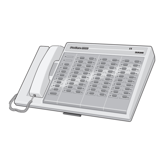
Section Master Station Controls and Operation ProCare 2000 DUKANE Master Station Speaker Volume Control Controls Rotate this control until speaker volume is at the desired incoming audio level. Note: This adjustment has no effect on the handset volume. Speaker The speaker allows communication from, and monitoring of, remote stations. - Page 16 (Master Station ERROR Indicator Controls) This LED flashes briefly when an invalid operation is attempted at the master station. The LED flashes rapidly when communication cannot be made between the master station and its central equipment cabinet. (Call authorized personnel for assistance.) If the LED flashes slowly, it may be an indication that the backup battery in the central equipment cabinet is running low.
- Page 17 (Master Station ALL PAGE/TIME Pushbutton and LED (see page 14, Paging) Controls) This pushbutton lets you use the handset to make a page announcement to all the audio-capable remote stations. It is also used to end the all page. The ALL PAGE LED lights during an all page and goes out when paging is completed.
- Page 18 (Master Station Remote Station Buttons and LEDs Controls) Pressing one of these pushbuttons begins or ends communication with the as- signed remote station. These pushbuttons can also be used for: Monitoring a station or zone. Paging a zone. Forwarding a call’s indication to another remote location. Setting the reminder feature.
-
Page 19: Important Master Station Indicators
Important The BUSY Indicator: Master Station — flashes slowly when there are no calls present in the system, to indicate that Indicators the master station is functioning properly. — stays lit when there is active communication at either master station. The ERROR Indicator: —... -
Page 20: System Response Chart
System Response Chart RESPONSE GENERATED ACTION IN PROGRESS Master Patient Duty Station Corridor Zone Light Follow Station Station Station Light Normal Call Slow Tone Steady Slow Tone Steady Steady Moderate Tone Slow Flash Light Slow Flash White White Moderate to Master Flash Rapid Tone Rapid Flash... -
Page 21: Responding To A Call
Responding Calls from remote stations are annunciated at the master station by an intermittent to a Call tone and a flashing LED alongside the corresponding station’s pushbutton. The flash and tone rates indicate the call’s priority. Emergency priority calls annunciate at a faster rate than normal calls. -
Page 22: Responding To A Call From Another Master Station In The System
(Responding Responding to a Call from Another Master Station in the System to a Call) 1. When the MASTER/SYSERR LED flashes, remove the handset from its cradle. 2. Press the pushbutton next to the flashing MASTER/SYSERR LED. The LED stops flashing and remains lit. 3. -
Page 23: Silencing Tones
Silencing 1. Press the SILENT/VOLUME pushbutton once to temporarily disable all the sound- Tones ing tones at the master station. The associated LED indicators continue to flash. 2. Press the SILENT/VOLUME pushbutton again to restore the tones. Notes: — The SILENT/VOLUME LED flashes when a call from any station is silenced. —... -
Page 24: Calling Another Master Station In The Same System
(Placing Calls) 3. If using the microphone/speaker, press the PUSH TO TALK button to talk, and release it to listen. If using the handset, talk into it as you would a conventional telephone receiver. 4. When conversation is finished, return the handset to its cradle or press the station button again. -
Page 25: Monitoring
Monitoring Up to eight preassigned zones, with up to 10 remote (patient, staff, and staff/duty) audio stations in each zone, can be monitored from the master station. During monitoring, the LED indicators of the monitored stations light on the master station. The privacy LED lights on the remote stations being monitored. -
Page 26: Locating A Station In Distress
(Monitoring) Locating a Station in Distress Press the ZONE pushbutton to exit zone monitoring, if in operation, then press each remote station button sequentially while pausing briefly to monitor the activities of each station. Monitoring Notes: — You can talk to remote stations in the monitored zone by removing the handset from the cradle and speaking into the handset. -
Page 27: Staff Follow
(Paging) 4. Make the page announcement using the handset. 5. Return the handset to its cradle or press the ZONE pushbutton again. The ZONE LED indicator goes out. Zone Assignment Notes: Stations can be reassigned to zones as needed. Consult with authorized personnel if this needs to be done. -
Page 28: Removing A Remote Station From Follow
(Staff Follow) 5. To check the follow designation at the master station, press the FOLLOW pushbutton. The LED indicator next to the designated follow station pushbutton lights. 6. Press FOLLOW again to return the master station to normal operation. Note: The FOLLOW pushbutton LED at the master station flashes whenever any remote station is assigned as a follow station. -
Page 29: Placing A Remote Station On Reminder
(Reminder) Placing a Remote Station on Reminder 1. Connect to the calling station by pressing that station’s numbered pushbutton. 2. Press the REMIND pushbutton. The REMIND LED lights, and the green sections in the corridor and zone lights flash. The calling station’s call assurance LED flashes. 3. -
Page 30: Placing Stations On Programmed Emergency
(Programmed Placing Stations on Programmed Emergency Emergency 1. Contact the calling station by pressing that station’s numbered pushbutton. Priority) The PRIORITY/LOCK LED indicator lights if the called station already has emergency priority status. 2. Press the PRIORITY/LOCK pushbutton to change the station’s emergency priority status. -
Page 31: Section 3-Patient Station Controls And Operation
Call Cord Receptacle with Adjacent Amber Call Assurance LED This receptacle accommodates all standard Dukane call cord devices not re- quiring entertainment. Unplugging the call device from the receptacle auto- matically places an emergency priority call that can only be canceled by reinserting the call device and pressing the CANCEL touchpad. - Page 32 (Single Patient CANCEL Touchpad Station Pressing CANCEL cancels any pending call placed from this station, and/or removes the station from reminder status. Models 4A3080 Red Privacy LED This red privacy LED lights whenever this station is in the intercommunica- 4A3180 tion mode or when it is being monitored by a master station.
-
Page 33: Single Patient Station With Entertainment-Models 4A3081A And 4A3181A Enhanced
Entertainment Option Receptacle This multi-pin connector accommodates all standard Dukane call cords and allows the use of a pillow speaker. The pillow speaker allows the patient to place a call to the associated master station and control TV functions. Inter- communication takes place through the patient station speaker/microphone. - Page 34 (Single Patient CANCEL Touchpad Station with Pressing CANCEL cancels any pending call placed from this station, and/or Entertainment removes the station from reminder status. Models Red Privacy LED 4A3081A This red privacy LED lights when this station is in the intercommunication mode or when it is being monitored by a master station.
-
Page 35: Dual Patient Station-Models 4A3085A And 4A3185 Enhanced
Call Cord Receptacle with Adjacent Amber Call Assurance LED The two call cord receptacles (one for each patient) accommodate all standard Dukane call cord devices without entertainment. Unplugging a call cord from a receptacle automatically places an emergency priority call that can be can- celed only by reinserting the call cord and pressing the CANCEL touchpad. -
Page 36: Dual Patient Station With Entertainment-Models 4A3086A And 4A3186A Enhanced
Entertainment Option Receptacles These multi-pin connectors accommodate all standard Dukane call cords and allow the use of a pillow speaker. The patient can use the pillow speaker to place a call to the associated master station or to control TV functions. Inter- communication takes place through the patient station’s speaker/microphone. - Page 37 CANCEL Touchpad (Dual Patient Station Press this touchpad to cancel any pending call placed from this station or to re- with move the station from reminder status. Entertainment Red Privacy LED Models The red privacy LED lights when this station is in the intercommunication 4A3086A mode or when it is being monitored by a master station.
-
Page 38: Single Patient Station With Pillow Speaker Intercom-Model 4A3182 Enhanced
Entertainment Option Receptacle This multi-pin connector accommodates all standard Dukane call cords and allows the use of a pillow speaker. Using the pillow speaker the patient can place a call to the associated master station and control TV functions. When a pillow speaker is installed, intercommunication takes place through the pillow speaker, and entertainment audio is muted. - Page 39 (Single Patient CANCEL Touchpad Station Press this touchpad to cancel any pending call placed from this station or to re- with Pillow move the station from reminder status. Speaker Intercom Red Privacy LED The red privacy LED lights when this station is in the intercommunication Model mode or when it is being monitored by a master station.
-
Page 40: Special Purpose Single Patient Station-Model 4A3183
Special Purpose Single Patient Station Model 4A3183 This patient station is normally used in conjunction with a bed safety rail communica- tion system. A pillow speaker can be substituted for the bed rail communication system. The patient can place a normal call or emergency call to the master station through the bed rail system or through the pillow speaker. - Page 41 CANCEL Touchpad (Special Purpose Single Patient Press this touchpad to cancel any pending call placed from this station or to Station remove the station from reminder status. Model Red Privacy LED 4A3183) The red privacy LED lights when this station is in the intercommunication mode or when it is being monitored by a master station.
-
Page 42: Dual Patient Station With Pillow Speaker Intercom-Model 4A3187 Enhanced
Entertainment Option Receptacles These multi-pin connectors accommodate all standard Dukane call cords and allow the use of a pillow speaker. The patient can use the pillow speaker to place a call to the associated master station, control TV functions, and select available audio programs. - Page 43 (Dual Patient Amber Call Assurance LED Station The amber LED lights each time a call is placed from this section and remains with lit until the call is answered from the master station or canceled at this patient Pillow Speaker station.
-
Page 44: Special Purpose Dual Patient Station-Model 4A3188
Special Purpose Dual Patient Station Model 4A3188 The special purpose dual patient station is used with a bed safety rail communication system. A pillow speaker can be substituted for the bed communication system. The patient can place a call to the master station through the bed rail system. Calls from this station are indi- cated at the master station, the duty stations, and the corresponding corridor and zone lights. -
Page 45: Lavatory/Emergency Station-Model 9A3005
Lavatory/ Emergency Station Model 9A3005 This station is activated by pulling the call cord, which places an emergency call to a master station. The call can only be canceled from the originating station by pressing the CANCEL touchpad, causing the LED indicator to go out. Call Cord Pulling the call cord places an emergency call to the master station and causes the red section of the associated corridor and zone lights to flash. -
Page 46: Shower Emergency Station-Model 9A3006
Shower Emergency Station Model 9A3006 This water-resistant station is designed for use in patient showers. It is activated by pulling the call cord, which places an emergency call to a master station. The call can only be canceled from the originating station by pressing the CANCEL touchpad, causing the LED indicator to go out. -
Page 47: Lavatory/Emergency Station-Model 9A3010
Lavatory/ Emergency Station Model 9A3010 This station is activated by pressing the large red touchpad, which places an emer- gency call to the master station. The call can only be canceled from the originating station by pressing the CANCEL touchpad, causing the LED indicator to go out. PUSH FOR HELP Touchpad Pressing this touchpad places an emergency call to the master station and causes the red section of the associated corridor and zone lights to flash. -
Page 48: Code Blue Station-Model 9A3015
Code Blue Station Model 9A3015 This station is activated by pressing the large blue touchpad, which places an emer- gency call to the master station. The call can only be canceled from the originating station by pressing the CANCEL touchpad, causing the LED indicator to go out. Distinct tone and visual annunciation at the master, duty, and follow stations is avail- able only if 437-00112 Option C or 437-00182 Option D firmware is installed and the call point is programmed as code blue at the master station. -
Page 49: Staff Emergency Station-Model 9A3020
Staff Emergency Station Model 9A3020 This station is activated by pressing the large green touchpad, which places an emer- gency call to the master station. The call can only be canceled from the originating station by pressing the CANCEL touchpad, causing the LED indicator to go out. Distinct tone and visual annunciation at the master, duty, and follow stations is avail- able only if 437-00112 Option C or 437-00182 Option D firmware is installed and the call point is programmed as staff emergency at the master station. -
Page 50: Staff Station-Model 4A3090
Staff Station Model 4A3090 This station provides call-in to the master station, intercommunication between this station and the master station, and monitoring of this station by the master station. Speaker/Microphone This speaker/microphone allows hands-free, two-way voice communications between the staff (or anyone else in the room) and the attendant at the associated master station without the person directing his/her voice toward the station panel or operating any controls. -
Page 51: Duty Station-Model 4A3091A
Duty Station Model 4A3091A This station transmits audio tones and visual indications of calls placed (normal or emergency) from any station within the system. The duty station allows staff to moni- tor incoming calls. Tone Sounder The tone sounder emits a tone to indicate incoming calls in the system. Tone Level Adjustment The LOW/HIGH tone level control allows two levels of tone volume at the station. -
Page 52: Staff/Duty Station-Model 4A3092A
Staff/Duty Station Model 4A3092A This station provides call-in to the master station, intercommunication between this station and the master station, and monitoring of this station by the master station. The staff/duty station transmits audio tones and visual indications for the type of call placed (normal or emergency) by a patient, staff, or emergency station in the system. - Page 53 (Staff/Duty Station CANCEL Touchpad Press to cancel any pending call placed from this station or to remove the sta- tion from reminder or follow status. Model 4A3092A) Call Touchpad with Call Assurance LED Pressing this touchpad places a call to the master station and lights the call as- surance LED, the station’s associated corridor and zone lights, and the associated LED indicator on the master station.
-
Page 54: Auxiliary Station-Model 9A3025
Auxiliary Station Model 9A3025 USE ONLY UL 544 LISTED AUXILIARY EQUIPMENT AUX INPUT The auxiliary input station is used to connect a monitor device, such as a portable ventilator unit or bed exit unit, to the nurse call system. When the monitor device is in alarm mode, a call is placed to the master station. -
Page 55: Section 4-Call Cord Controls And Operation
7A2010 7A2011 Model 7A2011 The 7A2010 and 7A2011 pillow speakers can be used only with a Dukane ProCare 2000 Patient Station equipped with the gray 17-pin entertainment connector. The patient can control entertainment functions through the pillow speaker. The pillow speaker is also used to place a normal or assigned priority calls to the master station. - Page 56 (Pillow Speaker Speaker This sensitive speaker provides entertainment audio. Models Note: 7A2010 Communication between this station and the master takes place through the pillow speaker on stations equipped with pillow speaker intercom. On stations 7A2011) not equipped with pillow speaker intercom, communication takes place through the station’s speaker/microphone.
-
Page 57: Pillow Speaker-Model 7A2031
Model 7A2031 The 7A2031 pillow speaker can be used with any Dukane ProCare 2000 special purpose patient station. This pillow speaker provides nurse call, basic TV, radio, and lighting controls for the patient. The pillow speaker is also used to place normal or assigned priority calls to the master station. - Page 58 (Pillow Speaker Speaker This sensitive speaker provides entertainment audio. Model 7A2031) Note: Communication between this station and the master takes place through the pillow speaker on stations equipped with pillow speaker intercom. On stations not equipped with pillow speaker intercom, communication takes place through the station’s speaker/microphone.
-
Page 59: Pillow Speaker-Models 7A2005 And 7A2006
7A2006 Model 7A2006 The 7A2005 and 7A2006 pillow speakers are normally used with any Dukane ProCare 2000 patient station equipped with the white 13-pin entertainment connector receptacle. (These pillow speakers can also be used with a gray 17-pin receptacle for a mixed system.) Both pillow speaker models provide nurse call and basic TV... - Page 60 (Pillow Speaker Speaker This sensitive speaker provides entertainment audio. Models 7A2005 Note: and 7A2006) Communication between this station and the master takes place through the pillow speaker on stations equipped with pillow speaker intercom. On stations not equipped with pillow speaker intercom, communication takes place through the station’s speaker/microphone.
-
Page 61: Smart Pillow Speaker-Model 7A/B/C2111
Speaker Model 7A/B/C2111 The Model 7A/B/C2111 Smart Pillow Speaker is used only with a Dukane ProCare 2000 patient station (Models 4A3081A, 4A3086A, 4A3181A, 4A3182, 4A3186A, and 4A3187) equipped with a gray 17-pin entertainment connector. The smart pillow speakers provide nurse call, TV, and lighting controls, plus control of the on/off, channel up/down, closed caption functions, and audio level of designated “Smart”... - Page 62 (Smart Pillow Speaker Speaker This sensitive speaker provides entertainment audio. Note: Model Communication between this station and the master takes place through the 7A/B/C2111) pillow speaker on stations equipped with pillow speaker intercom. On stations not equipped with pillow speaker intercom, communication takes place through the station’s speaker/microphone.
-
Page 63: Smart Pillow Speaker-Model 7A/B/C2131
Speaker Model 7A/B/C/2131 The Model 7A/B/C2131 Smart Pillow Speaker can be used with Dukane ProCare 2000 Special Purpose Patient Stations installed with a 37-pin connector wallplate receptacle connected to an electronically controlled bed manufactured by Stryker or Hill-Rom. The smart pillow speakers provide nurse call, TV, and lighting controls, plus control of the on/off, channel up/down, closed caption functions, and audio level of designated “Smart”... - Page 64 (Smart Pillow Speaker Speaker This sensitive speaker provides entertainment audio. Note: Model Communication between this station and the master takes place through the 7A/B/C2131) pillow speaker on stations equipped with pillow speaker intercom. On stations not equipped with pillow speaker intercom, communication takes place through the station’s speaker/microphone.
-
Page 65: Smart Pillow Speaker-Model 7A/B/C2106
Speaker Model 7A/B/C2106 The Model 7A/B/C2106 Smart Pillow Speaker is used with a Dukane ProCare 2000 patient station (Models 4A3081A, 4A3086A, 4A3181A, 4A3182, 4A3186A, and 4A3187) equipped only with a white13-pin entertainment connector. The smart pillow speakers provide nurse call, TV, and lighting controls, plus control of the on/off, channel up/down, closed caption functions, and audio level of designated “Smart”... - Page 66 (Smart Pillow Speaker Speaker This sensitive speaker provides entertainment audio. Note: Model Communication between this station and the master takes place through the 7A/B/C2106) pillow speaker on stations equipped with pillow speaker intercom. On stations not equipped with pillow speaker intercom, communication takes place through the station’s speaker/microphone.
-
Page 67: Pillow Speaker Hanger-Model 438-707 (Optional)
Pillow Speaker This hanger, available as an optional Hanger accessory, is secured on the wall near the patient station and cradles the pillow Model 438-707 speaker when it is not in use. (optional) Important Note: To help prevent damage, always place an unused pillow speaker in its hanger. -
Page 68: Air Cord Assembly-Models 200-1071 And 200-1073
Air Cord Assembly These assemblies provide nurse call capabilities to a patient with one patient Models 200-1071 station. Exclusively designed for patients and 200-1073 undergoing oxygen therapy. Both assem- blies have a large squeeze pad actuator for patients with impaired dexterity. Model 200-1071 is 6 feet (1.8 m) long. -
Page 69: Dual Call Cord Assembly-Models 200-1173 And 200-1174
Dual Call Cord These assemblies provide nurse call Assembly capabilities to two patients with one patient station. Models 200-1173 and 200-1174 Model 200-1173 is 6 feet (1.8 m) long. Model 200-1174 is 12 feet (3.7 m) long. Switch Plug This switch plug inserts into the front panel receptacle on a patient station for Model 570-130 pushbutton nurse call capabilities. - Page 70 Notes ProCare 2000 Operation Manual...
- Page 71 Section Lamp Operation Corridor Lamp Models 18A521 (1 bulb), 18A522 (2 bulb), 18A523 (3 bulb), 18A524 (4 bulb) Corridor lamps are usually located on the wall or ceiling outside a patient’s room. They light when a call is placed from that room to the master station, and go out when that call is answered.
- Page 72 Notes ProCare 2000 Operation Manual...
- Page 74 DUKANE CORPORATION COMMUNICATIONS SYSTEMS DIVISION - 2900 Dukane Drive, St. Charles, Illinois 60174 © 2000. Printed in USA. All specifications subject to change without notice.
Need help?
Do you have a question about the 4A3076B and is the answer not in the manual?
Questions and answers