Yamaha RX-V800 Service Manual
Av receiver
Hide thumbs
Also See for RX-V800:
- Owner's manual (82 pages) ,
- Service manual (46 pages) ,
- Owner's manual (72 pages)
Table of Contents
Advertisement
RX-V800/RX-V800RDS/HTR-5280
This manual has been provided for the use of authorized YAMAHA Retailers and their service personnel.
It has been assumed that basic service procedures inherent to the industry, and more specifically YAMAHA Products, are already
known and understood by the users, and have therefore not been restated.
WARNING:
IMPORTANT:
The data provided is believed to be accurate and applicable to the unit(s) indicated on the cover. The research, engineering, and
service departments of YAMAHA are continually striving to improve YAMAHA products. Modifications are, therefore, inevitable
and specifications are subject to change without notice or obligation to retrofit. Should any discrepancy appear to exist, please
contact the distributor's Service Division.
WARNING:
IMPORTANT:
CONTENTS
TO SERVICE PERSONNEL .......................................... 1
IMPEDANCE SELECTOR ............................................. 1
SPECIFICATIONS .......................................................... 2
FRONT PANELS ............................................................ 4
REAR PANELS .......................................................... 5~6
INTERNAL VIEW ........................................................... 7
DISASSEMBLY PROCEDURES ................................... 8
SELF DIAGNOSIS FUNCTION (DIAG) ................... 9~23
1 0 0 7 2 7
SERVICE MANUAL
IMPORTANT NOTICE
Failure to follow appropriate service and safety procedures when servicing this product may result in personal
injury, destruction of expensive components, and failure of the product to perform as specified. For these reasons,
we advise all YAMAHA product owners that any service required should be performed by an authorized
YAMAHA Retailer or the appointed service representative.
The presentation or sale of this manual to any individual or firm does not constitute authorization, certification or
recognition of any applicable technical capabilities, or establish a principle-agent relationship of any form.
Static discharges can destroy expensive components. Discharge any static electricity your body may have
accumulated by grounding yourself to the ground buss in the unit (heavy gauge black wires connect to this buss).
Turn the unit OFF during disassembly and part replacement. Recheck all work before you apply power to the unit.
AMP ADJUSTMENT .................................................... 23
IC DATA ................................................................. 25~31
BLOCK DIAGRAM ................................................. 32~35
PRINTED CIRCUIT BOARD .................................. 36~59
PIN CONNECTION DIAGRAM .............................. 60~61
SCHEMATIC DIAGRAM ........................................ 62~68
PARTS LIST ........................................................... 69~87
REMOTE CONTROL TRANSMITTER .................. 88~89
AV RECEIVER
P.O.Box 1, Hamamatsu, Japan
Advertisement
Table of Contents

Related Manuals for Yamaha RX-V800


Summary of Contents for Yamaha RX-V800
-
Page 1: Table Of Contents
This manual has been provided for the use of authorized YAMAHA Retailers and their service personnel. It has been assumed that basic service procedures inherent to the industry, and more specifically YAMAHA Products, are already known and understood by the users, and have therefore not been restated. -
Page 2: To Service Personnel
RX-V800/RX-V800RDS/HTR-5280 I TO SERVICE PERSONNEL 1. Critical Components Information AC LEAKAGE Components having special characteristics are marked s WALL EQUIPMENT TESTER OR and must be replaced with parts having specifications equal OUTLET UNDER TEST EQUIVALENT to those originally installed. 2. Leakage Current Measurement (For 120V Models Only) -
Page 3: Specifications
RX-V800/RX-V800RDS/HTR-5280 I SPECIFICATIONS I Audio Section S-Video Sigal Level Y ................. 1 Vp-p / 75 ohms Minimum RMS Output Power (Power Amp. Section) C ..............0.286 Vp-p / 75 ohms (20 Hz to 20 kHz, 0.04% THD, 8 ohms) MAIN ............... 100W + 100W Component Video Sigal Level CENTER ................ -
Page 4: Remote Control
RX-V800/RX-V800RDS/HTR-5280 • DIMENSIONS I REMOTE CONTROL TRANSMITTER INPUT HALL CHURCH JAZZ TUNER MD/TAPE ROCK ENTERTAINMENT TV SPORTS D-TV/LD VCR 1 MONO MOVIE 1-MOVIE THTR-2 CD-R CBL/SAT VCR 2/DVR /DTS SUR. 6.1/ES EFFECT PHONO 6CH INPUT V-AUX > ENTER 435 (17-1/8") -
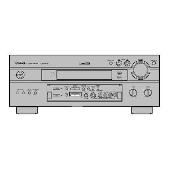
Page 5: Front Panels
I FRONT PANELS • U, C and A models → BL (Black model) RX-V800 (U, C, A, L, R, T models) • L model → GD (Gold model) • R and T models → BL (Black model) and GD (Gold model) -
Page 6: Rear Panels
RX-V800/RX-V800RDS/HTR-5280 I REAR PANELS U model DIGITAL OUTPUT AUDIO AUDIO VIDEO WARNING TO REDUCE THE RISK TUNER S VIDEO VIDEO COMPONENT OF FIRE OR ELECTRIC SHOCK, TAPE DO NOT EXPOSE THIS APPLIANCE TO RAIN OR MOISTURE. (PLAY) ATTENTION RISQUE DE CHOC... - Page 7 RX-V800/RX-V800RDS/HTR-5280 G model DIGITAL OUTPUT AUDIO AUDIO VIDEO TUNER S VIDEO VIDEO COMPONENT TAPE (PLAY) MD/TAPE CD-R D-TV (REC) SPEAKERS OUTPUT AC OUTLETS OPTICAL SWITCHED I00W MAX. TOTAL MAIN /SAT (PLAY) UNBAL. CD-R CD-R D-TV/LD MAIN (REC) VDR 1 D-TV...
-
Page 8: Internal View
RX-V800/RX-V800RDS/HTR-5280 I INTERNAL VIEW 1 POWER (3) P.C.B. A DSP P.C.B. K MAIN (3) P.C.B. 2 MAIN (5) P.C.B. B FUNCTION P.C.B. L POWER (1) P.C.B. 3 MAIN (2) P.C.B. C OPERATION (5) P.C.B. 4 VIDEO (3) P.C.B. D OPERATION (4) P.C.B. -
Page 9: Disassembly Procedures
RX-V800/RX-V800RDS/HTR-5280 I DISASSEMBLY PROCEDURES (Remove parts in the order as numbered.) Disconnect the power cord from the AC outlet. 1. Removal of Top Cover a. Remove 2 screws (1), 4 screws (2) and 5 screws (3) in Fig. 1. b. Slide the Top Cover rearward to remove it. - Page 10 RX-V800/RX-V800RDS/HTR-5280 SELF DIAGNOSIS FUNCTION (DIAG) There are 13 DIAG menu items each of which has sub-menu items. Listed in the table below are menu items and sub-menu items. No. DIAG menu sub-menu Remote control code (key) DSP THROUGH 1. ANALOG BYPAS (ANALOG BYPASS) 7A-90 (PRG 9) 2.
- Page 11 RX-V800/RX-V800RDS/HTR-5280 • Starting DIAG Press the “STANDBY/ON key while pressing those two keys indicated in the figure on the right. • Starting DIAG in the protection cancel mode Keys of main unit (in sealing panel) If the protection function works and causes hindrance to trouble diagnosis, cancel...
- Page 12 RX-V800/RX-V800RDS/HTR-5280 When there is a history of protection function: Cause: An excessive current flowed to the power amplifier. When there is a history of Supplementary information: As current of the power transistor is detected, the protection function against Version excess current (1 alphabet) abnormal channel can be identified by checking the current detect transistor.
- Page 13 RX-V800/RX-V800RDS/HTR-5280 • Functions in DIAG mode In addition to the DIAG menu items, functions as listed below are available. • Input selection, 6CH input • REC OUT (ZONE2) switching • Center/Rear/Sub-woofer level adjustment • Muting • Speaker relay A/B • Power on/off •...
- Page 14 RX-V800/RX-V800RDS/HTR-5280 • Details of DIAG menu 1. DSP THROUGH There are 3 sub-menu items (ANALOG BYPAS, DSP 0dB, DSP FULL BIT). ANALOG BYPASS [Remote control code: 7A-90 (PRG9)] • The input mode is fixed to use the analog (A/D) system.
- Page 15 RX-V800/RX-V800RDS/HTR-5280 DSP 0dB [Remote control code: 7A-91 (PRG 10)] • C/SWFR, FL/FR, RL/RR signals are output through DSP (see the signal path in the figure below) without using the external DRAM. (Head margin included) Head margin: Main L/R: 0dBFS, Center: -6dBFS, Rear Center: -3dBFS, FL/FR: -6dBFS, RL/ RR: -12dBFS, SWFR: Add L/R signal at -20dBFS.
- Page 16 RX-V800/RX-V800RDS/HTR-5280 2. HP ROUTE There are 2 sub-menu items (HP 0dB and HP FULL BIT). HP 0dB [REMOTE CONTROL CODE: 7A-93 (PRG 12)] • L/R, C/SWFR, FL/FR, RL/RR signals are output through DSP (see the signal path in the figure below) without using the external DRAM. (Head margin included) •...
- Page 17 RX-V800/RX-V800RDS/HTR-5280 3. RAM THROUGH The main L/R uses the analog through method when analog signals are input and the DSP through method when digital signals are input. The Center, FL/FR and RL/RR signals are output through the external DRAM. RAM 0dB [REMOTE CONTROL CODE: 7A-11 (PRESET-)]...
- Page 18 RX-V800/RX-V800RDS/HTR-5280 4. PRO LOGIC [YSS928] Operation conforming to the ordinary Dolby Normal sound field is provided. [REMOTE CONTROL CODE: 7A-0C (CD FF)] [2ch source] Same as ordinary Pro Logic except that the auto input balance function is off. ANALOG CODEC...
- Page 19 RX-V800/RX-V800RDS/HTR-5280 5. SPEAKERS SET The input signal is automatically identified in the order of dts DOLBY DIGITAL Analog. There are five sub-menu items as follows. The signals output from the DSP block are the same as 1. DSP THROUGH: DSP 0dB.
- Page 20 Noise is output from the SUB WOOFER channel. 8. RS-232C RX-V800 does not use this menu. 9. PRESET This menu is used to reserve and inhibit initialization of the back-up RAM. The signals are processed using EFFECT OFF. (The L/R signal is output using ANALOG MAIN BYPASS.) PRESET INHIBIT (Initialization inhibited) [REMOTE CONTROL CODE: –]...
- Page 21 During signal processing, the condition before execution of this menu is maintained. REC OUT [Remote control code: –] RX-V800 does not use this sub-menu. K0/K1 (Panel key of main unit) [Remote control code: –] A/D of the key fails to function properly when the standard value is deviated by ±4%.
- Page 22 RX-V800/RX-V800RDS/HTR-5280 11. IF STATUS Using the sub-menu, the status data is displayed one after another in the hexadecimal notation. During signal processing, the status before execution of this menu is maintained. * Numeric values in the figure example are for reference.
- Page 23 RX-V800/RX-V800RDS/HTR-5280 CS1-5 [Remote control code: -]: Indicates channel status information of the input signal (IEC60958). BI1-4 [Remote control code: -]: Indicates information of the bit stream included in the DOLBY DIGITAL signal. BS1-4 [Remote control code: -]: Indicates information of the bit stream included in the dts signal.
-
Page 24: Amp Adjustment
RX-V800/RX-V800RDS/HTR-5280 13. MICROPROCESSOR INFORMATION There are 4 sub-menu display. The version, checksum and the port specified by the microprocessor are displayed. The signal is processed using EFFECT OFF. The checksum is obtained by adding the data at every 16 bits for each program area and expressing the result as a 4- figure hexadecimal data. -
Page 25: Display Data
RX-V800/RX-V800RDS/HTR-5280/DSP-AX8 I DISPLAY DATA G V901 : 16-BT-81GK (V5917600) PATTERN AREA G PIN CONNECTION Pin No. Connection Pin No. Connection Note : 1) F1, F2 ..Filament 2) NP ..No pin 3) DL ..Datum Line 4) 1G ~ 16G ..Grid 5) IC .. -
Page 26: Ic Data
RX-V800/RX-V800RDS/HTR-5280/DSP-AX8 I IC DATA IC501 : YSS928 PHONO EQ RAMA9 RAMA3 SELI1 RAMA4 SELI0 SELI9 SELOA SELI10 SELOB SELI11 TESTMS SELI12 TESTXEN SELI13 IPORT0 RAMA2 IPORT1 RAMA5 IPORT2 RAMA1 IPORT3 RAMA6 RAMA0 IPORT4 DDIN0 RAMA7 DDIN1 RAMA8 DDIN2 VDD1 DDIN3... - Page 27 RX-V800/RX-V800RDS/HTR-5280 IC501 : YSS928 Pin Description Name Function Crystal oscillator connection terminal Crystal oscillator connection terminal (24.576 MHz) SELI1 Built-in selector input 1 SELI0 Built-in selector input 0 SELOA Built-in selector A output SELOB Built-in selector B output TESTMS Test terminal Unconnected...
- Page 28 RX-V800/RX-V800RDS/HTR-5280 Name Function – VDD2 – +2.5V power supply (for internal circuit) RAMD0 I+/O SubDSP: Data terminal 0 for external memory RAMD1 I+/O SubDSP: Data terminal 1 for external memory RAMD2 I+/O SubDSP: Data terminal 2 for external memory RAMD3...
- Page 29 RX-V800/RX-V800RDS/HTR-5280 Name Function SELI4 Built-in selector input 4 – SELI3 Built-in selector input 3 SELI2 Built-in selector input 2 TESTXI Test terminal Must be connected with VSS. TESTXO Test terminal Unconnected. VDD2 – +2.5V power supply (for internal circuit) Is: Schmidt trigger input terminal...
- Page 30 RX-V800/RX-V800RDS/HTR-5280/DSP-AX8 IC526 : M30802SGP 16bit µ-COM (Main CPU) /WRL/WR/CASL /WRH/BHE/CASH /RD/DW /BCLK/ALE/CLK M30802SGP /HLDA/ALE /HOLD /ALE/RAS /RDY /K13 /K12 /CYS /RTS /K11 /CLK /K10 /CTS /RTS /CTS /CLKS /CLK /SDA (*1) 0OUT /SCL (*1) N channnel Open Drain Output I/O Port...
- Page 31 RX-V800/RX-V800RDS/HTR-5280 IC526 : M30802SGP Pin Description Port No. Function name Detail of function TXDR 232C transmission data / Yokokawa data transmission 232C RTS output / Yokokawa clock input 232C CTS input Fan control SDTN None audio serial transmission data (necessary port)
- Page 32 RX-V800/RX-V800RDS/HTR-5280 Port No. Function name Detail of function Microcomputer ground Just before Just before Just before Just before Just before Just before Just before Just before Just before P124 SCKA Clock output for audio IC P123 SDTA Data output for audio IC...
-
Page 33: Block Diagram
RX-V800/RX-V800RDS/HTR-5280/DSP-AX8 I BLOCK DIAGRAM (1/2) IC601 IC607 Q601, 604 D-TV / IC602 IC603 Q609 VCR2 / IC607 IC610 LC74781-9798 IC609 25, 35 1, 11 VCR2 / IC609 21, 31 7, 17 Q701 IC607 IC601 IC702 D-TV / VCR2 / IC701... - Page 34 RX-V800/RX-V800RDS/HTR-5280/DSP-AX8 I BLOCK DIAGRAM (2/2) • See page E-62/J-58 → SCHEMATIC DIAGRAM FUNCTION FLASH ROM IC527 from MAIN (U, C, A only) • See page E-64/J-60 → SCHEMATIC DIAGRAM SW964 IC526 IC901 M30802SGP LDD Limit Detect IC501 YSS928 DIGITAL OUT...
-
Page 35: Printed Circuit Board
RX-V800/RX-V800RDS/HTR-5280/DSP-AX8 • Semiconductor Location I PRINTED CIRCUIT BOARD (Foil side) Ref. No. Location Ref. No. Location Ref. No. Location Ref. No. Location Ref. No. Location Ref. No. Location D517 D525 IC506 IC516 IC525 Q504 D518 D526 IC507 IC518 IC526 Q507... - Page 36 RX-V800/RX-V800RDS/HTR-5280/DSP-AX8 I PRINTED CIRCUIT BOARD (Foil side) • Semiconductor Location Ref. No. Location D501 D502 D503 D504 Q505, 506 D505 R603, 641, 677 D506 R673 D507 D508 D509 D510 D511 D512 D519 D528 D529 x: NOT USED Q505 O: USED / APPLICABLE...
- Page 37 RX-V800/RX-V800RDS/HTR-5280/DSP-AX8 I PRINTED CIRCUIT BOARD (Foil side) OPERATION (1) P. C. B. 6CH INPUT VOLUME INPUT INPUT MODE R941-944 OPERATION (3) P. C. B. FUNCTION (1) To: OPERATION (3) x: NOT USED O:USED / APPLICABLE /BESW OPERATION (2) P. C. B.
- Page 38 RX-V800/RX-V800RDS/HTR-5280/DSP-AX8 I PRINTED CIRCUIT BOARD (Foil side) OPERATION (4) P. C. B. OPERATION (5) P. C. B. VIDEO AUX OPTICAL SILENT S VIDEO VIDEO AUDIO L AUDIO R HPMT /HPI –12 /BEC D971 D972 D973 /HPI To: FUNCTION /HPI To: OPERATION (5)
- Page 39 RX-V800/RX-V800RDS/HTR-5280/DSP-AX8 • Semiconductor Location I PRINTED CIRCUIT BOARD (Foil side) Ref. No. Location D501 D502 DSP P. C. B. D503 D504 D505 D509 To: FUNCTION D511 D512 D513 D527 D528 D529 D531 IC501 IC502 IC506 IC509 IC513 IC514 IC520 TAPE...
- Page 40 RX-V800/RX-V800RDS/HTR-5280/DSP-AX8 • Semiconductor Location I PRINTED CIRCUIT BOARD (Foil side) Ref. No. Location D509 D510 D514 D516 D517 D518 D519 D521 D522 D524 D525 D526 D530 D532 D533 D534 D535 D536 D537 IC507 IC508 IC510 IC511 IC515 IC516 IC517 IC518...
- Page 41 RX-V800/RX-V800RDS/HTR-5280/DSP-AX8 To: VIDEO (3) • Semiconductor Location I PRINTED CIRCUIT BOARD (Foil side) Ref. No. Location From: MAIN (1) FUNCTION VIDEO (2) D231 VIDEO (1) P. C. B. D233 D234 D235 D601 D602 D603 D604 D605 D-TV D606 D607 D608...
- Page 42 RX-V800/RX-V800RDS/HTR-5280/DSP-AX8 • Semiconductor Location I PRINTED CIRCUIT BOARD (Foil side) Ref. No. Location IC701 IC702 IC751 VIDEO (2) P. C. B. VIDEO (3) P. C. B. IC752 Q701 VIDEO MONITOR OUT D-TV/LD COMPONENT VCR 2 VCR 1 /DVR D-TV MONITOR...
- Page 43 RX-V800/RX-V800RDS/HTR-5280/DSP-AX8 • Semiconductor Location I PRINTED CIRCUIT BOARD (Foil side) Ref. No. Location Ref. No. Location Ref. No. Location MAIN (1) P. C. B. x: NOT USED From: MAIN (3) O: USED / APPLICABLE From: MAIN (3) From: MAIN (3)
- Page 44 RX-V800/RX-V800RDS/HTR-5280/DSP-AX8 • Semiconductor Location I PRINTED CIRCUIT BOARD (Foil side) Ref. No. Location D151 D152 D153 D154 D204 D205 MAIN (2) P. C. B. MAIN (3) P. C. B. D206 D207 Q151 MAIN SPEAKERS Q154 Q156 Q158 Q201 Q203 From:...
- Page 45 RX-V800/RX-V800RDS/HTR-5280/DSP-AX8 • Semiconductor Location I PRINTED CIRCUIT BOARD (Foil side) Ref. No. Location D301 D351 POWER (1) P. C. B. POWER (3) P. C. B. D352 From: AC power cord From: From: POWER (2) From: POWER (2) POWER (2) VOLTAGE SELECTOR...
- Page 46 RX-V800/RX-V800RDS/HTR-5280/DSP-AX8 • Semiconductor Location I PRINTED CIRCUIT BOARD (Foil side) Ref. No. Location D851 POWER (8) P. C. B. IC351 IC352 FUNCTION IC353 AUDIO IC354 POWER (6) P. C. B. IC355 VCR 2 VCR 1 /DVR D-TV ZONE 2 /SAT...
-
Page 47: Pin Connection Diagram
RX-V800/RX-V800RDS/HTR-5280/DSP-AX8 I PIN CONNECTION DIAGRAM • ICs µPC29M33T-E1 AN78N05 NJM79M05FA PQ025EZ5MZP NJM7805FA NJM79M12FA NJM7812FA NJM78M05FA 3: IN 2: COM 3: OUT 3: IN 1: COM 1: OUT 1: OUT 2: IN 2: COM NJM2068MD NJM2068LD TC4066BP TC74HC00AF NJM2904M NJM4556AL TC74HCU04AF... - Page 48 RX-V800/RX-V800RDS/HTR-5280/DSP-AX8 • Diodes 1N4002S MTZJ5.6B 1SS355 1SR139 MTZJ6.8A RB501V-40 Anode Anode 1SS133 MTZJ9.1A 1SS270A MTZJ11B MTZJ12A HZS7B2TD MTZJ12C MTZJ4.7C MTZJ16A Cathode MTZJ5.1A MTZJ30.0A Cathode D2SBA20 S5VB20 — — • Transistors 2SB1565 2SA893A 2SA933S 2SA1492 2SA1015 2SC1740S 2SD2396 2SC3856 2SB949 2SD1915F...
-
Page 49: Schematic Diagram
#503 E-65/J-61 RX-V800/RX-V800RDS/HTR-5280/DSP-AX8 SCHEMATIC DIAGRAM (FUNCTION) to OPE (4) E-64/J-60 E-65/J-61 IC501: NJM2068MD IC502: LC78212 IC506, IC507, IC511, IC513~IC515: µPC4570G2 Analog Function Switch IC521, IC523~ICIC525: µPC4570G2 Dual OP-Amp –IN LCOM1 RCOM1 – – –IN INPUT SELECTOR DIGITAL IN –V 11.9... - Page 50 RX-V800/RX-V800RDS/HTR-5280/DSP-AX8 SCHEMATIC DIAGRAM (OPERATION 1/2) E-62/J-58 FL DISPLAY VOLUME -21.7 -29.8 -20.8 -18.6 -14.0 -20.9 FL DRIVER -26.8 -21.0 -26.7 -25.5 -26.7 -28.0 -26.7 -28.0 -26.8 -26.7 -26.7 -26.7 -20.6 -16.0 -17.0 -26.7 -16.0 -26.7 -18.6 -26.7 -14.0 -26.6 -26.6 -23.0...
- Page 51 RX-V800/RX-V800RDS/HTR-5280/DSP-AX8 SCHEMATIC DIAGRAM (DSP) E-62/J-58 to FUNC (1) IC507, IC513: TC74HC00AF IC510, IC511: TC74HCU04AF Quad 2-Input Nand Gate REGULATOR MAIN L IC508: TC74VHCT08AF Quad 2-Input And Gate 11.9 1000/6.3 -11.3 -11.3 DIGITAL OUT INHIBIT 1000/6.3 -11.3 PHONO EQ -11.9 D/A CONVERTER...
- Page 52 RX-V800/RX-V800RDS/HTR-5280/DSP-AX8 SCHEMATIC DIAGRAM (OPERATION 2/2) IC801: TC4066BP Quad Analog Switch/Multiplexer IN/OUT1 OUT/IN1 CONT1 OUT/IN2 CONT4 IN/OUT2 IN/OUT4 CONT2 OUT/IN4 CONT3 OUT/IN3 IN/OUT3 CB974 IC802, IC803: NJM2068LD Dual OP-Amp IC804: NJM4556AL Dual OP-Amp 2, 6 OUTPUT –INPUT 1, 7 +INPUT 3, 5...
- Page 53 RX-V800/RX-V800RDS/HTR-5280/DSP-AX8 SCHEMATIC DIAGRAM (VIDEO) IC601: TK15420M IC602, IC603, IC702: TC74HC4051AP Video Amp Analog Multiplexer/Demultiplexer OUT A E-66/J-62 –IN A OUT B – – +IN A –IN B +IN B 46.6 46.5 46.6 47.1 IC607, IC752: TC74HC4053AP INPUT SELECTOR -4.8 Analog Multiplexer/Demultiplexer 25.4...
- Page 54 RX-V800/RX-V800RDS/HTR-5280/DSP-AX8 SCHEMATIC DIAGRAM (MAIN) FRONT L POWER AMP 46.5 46.5 46.2 46.5 46.2 36.5 -0.4 24.2 -1.0 12.2 36.1 36.8 36.8 -0.5 -0.5 -1.0 -1.0 -46.5 -46.5 -45.3 FRONT R POWER AMP 46.5 46.5 46.2 -0.4 -1.0 -11.8 -0.5 -0.5 -11.8...
- Page 55 RX-V800/RX-V800RDS/HTR-5280/DSP-AX8 SCHEMATIC DIAGRAM (POWER) POWER RELAY 13.2 13.1 VOLTAGE SELECTOR 240V 1-2/5-6 220V 2-3/6-7 110V 3-4/7-8 120V 4-5/8-1 E-62/J-58 E-62/J-58 REGULATOR 17.1 12.0 17.7 -17.3 -12.0 -17.7 29.4 16.3 -0.1 -0.1 -9.7 -9.2 -4.8 x: NOT USED O: USED / APPLICABLE...
-
Page 56: Parts List
RX-V800/RX-V800RDS/HTR-5280 I WARNING PARTS LIST Components having special characteristics are marked s and must be replaced with parts having specifications equal to those originally in- stalled. I ELECTRICAL PARTS Carbon resistors (1/6W or 1/4W) are not included in the ELECTRICAL PARTS List. - Page 57 RX-V800/RX-V800RDS/HTR-5280 P.C.B. FUNCTION Schm Schm Ref. PART NO. Description Ref. PART NO. Description ✻ New Parts ✻ New Parts...
- Page 58 RX-V800/RX-V800RDS/HTR-5280 P.C.B. FUNCTION Schm Schm Ref. PART NO. Description Ref. PART NO. Description New Parts New Parts...
- Page 59 RX-V800/RX-V800RDS/HTR-5280 P.C.B. FUNCTION & P.C.B. OPERATION Schm Schm Ref. PART NO. Description Ref. PART NO. Description ✻ New Parts ✻ New Parts...
- Page 60 RX-V800/RX-V800RDS/HTR-5280 P.C.B. OPERATION & P.C.B. DSP Schm Schm Ref. PART NO. Description Ref. PART NO. Description ✻ New Parts ✻ New Parts...
- Page 61 RX-V800/RX-V800RDS/HTR-5280 P.C.B. DSP Schm Schm Ref. PART NO. Description Ref. PART NO. Description ✻ New Parts ✻ New Parts...
- Page 62 RX-V800/RX-V800RDS/HTR-5280 P.C.B. DSP & P.C.B. VIDEO Schm Schm Ref. PART NO. Description Ref. PART NO. Description ✻ New Parts ✻ New Parts...
- Page 63 RX-V800/RX-V800RDS/HTR-5280 P.C.B. VIDEO Schm Schm Ref. PART NO. Description Ref. PART NO. Description ✻ New Parts ✻ New Parts...
- Page 64 RX-V800/RX-V800RDS/HTR-5280 P.C.B. VIDEO & P.C.B. MAIN Schm Schm Ref. PART NO. Description Ref. PART NO. Description ✻ New Parts ✻ New Parts...
- Page 65 RX-V800/RX-V800RDS/HTR-5280 P.C.B. MAIN Schm Schm Ref. PART NO. Description Ref. PART NO. Description ✻ New Parts ✻ New Parts...
- Page 66 RX-V800/RX-V800RDS/HTR-5280 P.C.B. MAIN & P.C.B. POWER Schm Schm Ref. PART NO. Description Ref. PART NO. Description ✻ New Parts ✻ New Parts...
- Page 67 RX-V800/RX-V800RDS/HTR-5280 P.C.B. POWER & Chip Resistors Schm Schm Ref. PART NO. Description Ref. PART NO. Description ✻ New Parts ✻ New Parts...
- Page 68 RX-V800/RX-V800RDS/HTR-5280 I EXPLODED VIEW 3-11 200-1 3-21 R,T only 2-56 3-22 R,B,G,T models 3-33 2-21 2-57 R,B,G,T models 3-31 2-52 3-25 2-41 2-60 2-52 2-56 2-57 2-13 2-57 2-25 2-11 2-40 2-55 2-55 2-57 2-26 2-22 2-27 2-54 2-12 2-55...
- Page 69 RX-V800/RX-V800RDS/HTR-5280 I MECHANICAL PARTS Ref. Ref. PART NO. Description Remarks Markets PART NO. Description Remarks Markets ✻ New Parts ✻ New Parts...
- Page 70 RX-V800/RX-V800RDS/HTR-5280 Ref. PART NO. Description Remarks Markets ✻ New Parts...
- Page 71 RX-V800/RX-V800RDS/HTR-5280 Ref. PART NO. Description Remarks Markets ✻ New Parts...
- Page 72 RX-V800/RX-V800RDS/HTR-5280 Parts List for Carbon Resistors Value 1/4W Type Part No. 1/6W Type Part No. Value 1/4W Type Part No. 1/6W Type Part No. 3100 3100 10 k 7100 7100 HJ35 HF85 HF45 HF45 ❊ 3180 11 k 7110 7110...
-
Page 73: Remote Control Transmitter
RX-V800/RX-V800RDS/HTR-5280/DSP-AX8 I REMOTE CONTROL TRANSMITTER G SCHEMATIC DIAGRAM... - Page 74 RX-V800/RX-V800RDS/HTR-5280/DSP-AX8...
- Page 75 RX-V800/RX-V800RDS/HTR-5280...
Need help?
Do you have a question about the RX-V800 and is the answer not in the manual?
Questions and answers