Table of Contents
Advertisement
Quick Links
TR270 FM Transceiver
Owner's Manual
POWER
MIC
© Copyright 1997 R. L. Drake Company
TR270 FM Transceiver
VOLUME
SQUELCH
A
B
is a registered trademark of the R. L. Drake Company
®
®
REV
+
NUM
TEMP
SCAN
DEC
DATA
SAT
DATA
W
DTMF
TOT
ENC
VOICE
WXSAT
VOICE
N
A
MODE
B
HOLD TO SCAN
1
2
3
A
PRIO
VFO
MEM
A / B
4
5
6
B
RPT
REV
SAT
MODE
7
8
9
C
DTMF
CTS
B BW
P. OUT
*
0
#
D
NUM
LOCK
STORE
SETUP
P/N: 3851400A-5-1997
Printed in the U. S. A.
LMH
VFO 1
PW
VFO 2
MEM
A
TX
RX
B
RX
VFO 1
PW
VFO 2
MEM
LOCKED
SETUP
XMT DCD CON
MAIL
STA
TNC STATUS
TUNING
Downloaded by
Amateur Radio Directory
Advertisement
Table of Contents

Related Manuals for DRAKE TR270


Summary of Contents for DRAKE TR270
- Page 1 MODE DTMF B BW P. OUT LOCK STORE SETUP Downloaded by Amateur Radio Directory is a registered trademark of the R. L. Drake Company ® © Copyright 1997 R. L. Drake Company P/N: 3851400A-5-1997 Printed in the U. S. A.
- Page 2 Important Safeguards WARNING: TO PREVENT FIRE OR ELECTRICAL SHOCK DO NOT An appliance and cart combination should be moved EXPOSE TO RAIN OR MOISTURE with care. Quick stops, excessive force and uneven surfaces may cause the appliance and cart combina- tion to overturn.
- Page 3 Important Safeguards, continued 15. Overloading—Do not overload wall outlets and extension cords as this 19. Replacement Parts—When replacement parts are required, be sure can result in a risk of fire or electric shock. the service technician has used replacement parts specified by the 16.
-
Page 4: Table Of Contents
Table of Contents Thank you for purchasing a Drake TR270 FM Transceiver. Please carefully read the Owner's Manual in order to take advantage of the many interesting features that This transceiver has been designed and manufactured to high quality standards, and will provide reliable will provide enjoyable radio operation. -
Page 5: Specifications And Accessories
-75 dB min. IF Rejection: 75 dB min. Image Rejection: 60 dB min. *142 - 150 MHz operation with proof of MARS or CAP license. ACCESSORIES FOR THE TR270: TNC270 module Downloaded by DEMOD270 module Carrying handle Amateur Radio Directory... -
Page 6: Introduction
SETUP DESCRIPTION The unit permits DTMF and CTCSS tone encoding/ The TR270 is a table-top, base station, amateur radio 2 Meter FM Transceiver plus an additional extended range decoding of transceiver ‘A’. A hand held microphone with push-to-talk feature is included with the TR270. -
Page 7: Safety / Voltage Selection
Introduction - Safety / Voltage Selection WARNING NOTE: THE FOLLOWING PROCEDURE REQUIRES REMOVAL OF AN EQUIPMENT COVER THAT EXPOSES POTENTIALLY LETHAL VOLTAGES IF THE EQUIPMENT IS POWERED FROM AN AC POWER SOURCE. REFER SERVICING TO A QUALIFIED TECHNICIAN ONLY. NOTE: A magnetized screwdriver facilitates the removal and installation of screws in the procedure that follows: C) Locate the power supply cover. - Page 8 D) Ensure that the jumper is set for either the 115 VAC or the 230 VAC position as required for the AC Mains supply. Install the proper fuse at the rear panel of the TR270. 115 VAC 230 VAC JUMPER...
-
Page 9: Installation
Connect DC power Locate the registration card, fill out, and immediately observing correct polarity and fusing (10 A Fast Blow return to the R. L. Drake Company to insure registration and maximum) to avoid possible vehicle wiring damage validation of warranty. -
Page 10: Installation Diagram
EXTERNAL DC TNC UNIT CONNECTOR (supplied) FROM SW8, R8 SERIES RECEIVER AC POWER LINE AUDIO OUT FOR CW, RTTY, CORD EXTERNAL HF FAX, WE FAX RECEPTION CONNECTION SPEAKER (with optional Drake DEMOD270) ---------- --------- TERMINAL OR PC FIGURE 3 INSTALLATION DIAGRAM... -
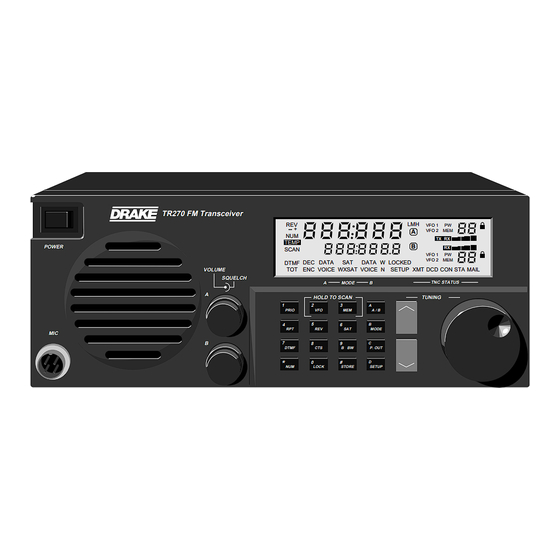
Page 11: Front Panel Description
Front Panel Description TR270 FM Transceiver VFO 1 VFO 2 TEMP POWER SCAN VFO 1 VFO 2 DTMF DATA DATA LOCKED VOLUME VOICE WXSAT VOICE SETUP XMT DCD CON MAIL SQUELCH TNC STATUS MODE HOLD TO SCAN TUNING PRIO A / B... -
Page 12: Microphone Connector Wiring Sense
Front Panel Description, continued 4) Program Buttons - - Press for a second function keyshift. When pressed, the orange button functions are active, - Press once to switch the selected transceiver/ PRIO (i.e. 0-9, *, #, A, B, C, D). receiver frequency to the programmed priority channel frequency. -
Page 13: Front Panel Display
Front Panel Display 23 24 VFO 1 VFO 2 TEMP TX RX SCAN VFO 1 DTSS VFO 2 DATA DATA LOCKED DTMF VOICE WXSAT VOICE SETUP XMT DCD CON MAIL 12 13 FIGURE 5 FRONT PANEL DISPLAY 1) 6-Digit Numeric Display Readout - This display CON (connect) - TNC is connected to a station indicates frequency, in ‘MHz’, for the ‘A’... - Page 14 Front Panel Display, continued 15) W/N Indicators - Wide or narrow IF filter is selected for receiver ‘B’. 16) - /+/REV Indicators - Refers to transmit offset selection. A) ‘-’ lit: Receive frequency is displayed, transmit frequency is 600 kHz lower in frequency (unless variable offset is programmed).
-
Page 15: Rear Panel Description
Rear Panel Description 115 OR 230 VAC SET INTERNALLY FACTORY SET : 115 V LINE FUSE 3 A,250 V 115 V SLO - BLO 230 V T 1.6 A,250 V +13.6 V A N T E N N A 2 A N T E N N A 1 RECEIVE ONLY RECEIVE : VHF/UHF... - Page 16 Rear Panel Description, continued 6) DC INPUT - This connector is used for powering the TR270 from an external DC source such as a car battery. Observe proper polarity when wiring the mating con- nector. This input is UNFUSED and thus requires an external (10 Amp, FAST BLOW) fuse to be wired in series with the external wiring supplying this connector.
-
Page 17: Getting Started
3. Connect the transceiver to a source of AC power. ments to read through this section and familiarize Switch power on to the TR270 with the POWER switch. yourself with general operating information. The front panel display should light and show VFO 1 selected for Receiver ‘A’. -
Page 18: Dual Vfo's
Getting Started cont'd. 8. Press the microphone PTT button and begin speaking. The tuning wheel incorporates two-speed tuning. The transmitted signal frequency is displayed during Rotating the tuning wheel faster, results in an increased transmit. tuning speed. 9. To receive on the ‘B’ receiver, Press the button to A / B Button Steps... -
Page 19: Setup Menu
NOTE: The SETUP mode can be entered only from the RESTORE FACTORY SETUP SETTINGS Priority, VFO, or Memory states (and from the special The TR270 is factory programmed for the default SETUP case of Inband or Crossband Repeater configuration). settings as shown in this section of the manual. To... - Page 20 Delay = 250 mSec. X N 3, 4 where N = 0, 1, 2, 3, 4 SETUP 0 = audio source internal to Demodulator Source 0 or 1 TR270 (if DEMOD 270 de- 1 = audio source external to modulator card is TR270 installed) SETUP...
- Page 21 Setup Menu, continued OPTION / PARAMETER SETUP MODE DISPLAY DESCRIPTION (factory defaults shown) NUMBER FUNCTION 0 = no audible beep when Set audible beep on button is pressed or off for any button 0 or 1 1 = audible beep when depression button is pressed SETUP...
- Page 22 Setup Menu, continued OPTION / PARAMETER SETUP MODE DISPLAY DESCRIPTION (factory defaults shown) NUMBER FUNCTION Enter frequency Receiver A - Program (for example: 148.0000) STOP frequency endpoint for VFO Scan SETUP Enter frequency Receiver B - Program (for example: 136.0000) START frequency endpoint for VFO Scan...
- Page 23 Setup Menu, continued OPTION / PARAMETER SETUP MODE DISPLAY DESCRIPTION (factory defaults shown) NUMBER FUNCTION 30 = List #0 Receiver A: 30 - 39 31 = List #1 Construct Memory Channel List (ten lists with a SETUP maximum of 10 38 = List #8 channels each list- List index 0 - 9...
- Page 24 Setup Menu, continued OPTION / PARAMETER SETUP MODE DISPLAY DESCRIPTION (factory defaults shown) NUMBER FUNCTION Sets the delay time Press to set the Delay between the end of a time prior to resuming SAT SAT LOCKED condition SCAN, (for example, to set and the continuation 5 seconds, set the number SETUP...
-
Page 25: Memory Functions
Memory Functions The TR270 has 400 programmable memory locations that - To load successive memory locations quickly, start in are allocated as follows: the VFO mode with the first desired frequency and the Transceiver ‘A’: 100 memories. desired starting memory channel number. From the VFO Receiver ‘B’: 100 memories, plus 100 additional memories... -
Page 26: Locking A Memory Channel
Memory Functions, continued Receiver ‘B’: Setup Mode #27 - set for ‘2’, and RESTORE FACTORY MEMORY PROGRAMMING Setup Mode #40 - Selects list #0. Construct the list with a With power off, press and hold the button maximum of 10 channels. From Setup #40, index from 0-9 while switching the power to ‘On’. -
Page 27: Scan Functions
Scan Functions The TR270 is capable of several different methods and modes of scanning frequencies. Both Receiver ‘A’ and Receiver ‘B’ provide the follow- ing: Scan Mode: Either VFO or Memory Scan Method: SEEK (0) - Stop scan at first detected carrier and exit the scan mode. -
Page 28: Scan Memory
Scan Functions, continued NOTE 2: SCAN MEMORY 1. Signal detection (stop scan on detected carrier) is dependent upon the strength of the signal, the squelch - SCAN ALL UNLOCKED MEMORY CHANNELS control setting, and the status of the preprogrammed subaudible tone squelch decoder (CTCSS “off” or “on”). For Receiver ‘A’: 1) Select SETUP #24 - set to ‘0’... - Page 29 Scan Functions, continued -SCAN ALL UNLOCKED MEMORY CHANNELS WITHIN A 4) Select SETUP #19 - set to: ‘0’ for a Seek scan PROGRAMMED RANGE OF MEMORY CHANNELS. ‘1’ for a Carrier scan ‘2’ for a Time scan For Receiver ‘A’: ‘3’...
-
Page 30: Scan Vfo
Scan Functions, continued For Receiver ‘B’: SCAN VFO A VFO scan permits continuous tuning of frequencies Select LIST scanning: between two programmed limits. 1) Select SETUP #27 - set to ‘2’. For Receiver ‘A’: 1) Select SETUP #20 - enter the START frequency endpoint SETUP from 144 - 148 MHz. -
Page 31: Locking A Memory Channel
Scan Functions, continued For Receiver ‘B’: 1) Select SETUP #22 - enter the START frequency endpoint from 136 - 174 MHz or 420 - 470 MHz. SETUP 2) Select SETUP #23 - enter the STOP frequency endpoint from 136 - 174 MHz or 420 - 470 MHz. SETUP 3) Select SETUP #05 - set to 5, 10, 12.5, 15, 20, or 25 kHz step size. -
Page 32: Voice Operation
Voice Operation VOICE OPERATION STANDARD OFFSETS The TR270 is capable of FM voice operation over a TR270 Repeater Offsets (Auto mode, Setup #00 = 1): simplex or repeater frequency pair. Additionally, by Repeater Frequency Offset using receiver ‘B’, a crossband repeat function is also (MHz) available. -
Page 33: Subaudible Tone Operation
Subaudible Tone Table: any signals that exceed the signal level threshold set by the squelch control. If you desire the TR270 to only Nominal Tone Frequency (Hz) respond to signals transmitting a subaudible tone, the 67.0... -
Page 34: To Store A Phone Number
Voice Operation, continued TO STORE A PHONE NUMBER INBAND REPEAT AND CROSSBAND REPEAT OPERATION The TR270 can be configured to use the 'B' receiver and 1) Press the button, and within 5 seconds, Press 0-9 DTMF 'A' transmitter as a repeater. -
Page 35: Crossband Repeat Operation
Voice Operation, continued To use the Crossband repeat mode, only a single RECEIVER ‘B’ SUBAUDIBLE TONE DECODE: antenna is required since the TR270 has an internal If the subaudible tone decoder is enabled for receiver crossband duplexer. Two separate antennas may also ‘B’, the transmitter will not be keyed unless the (‘B’) -
Page 36: Satellite Operation
Satellite Operation INTRODUCTION TO SATELLITE OPERATION The TR270 supports both full duplex, packet data and voice operation through the orbiting amateur satellites. While most of these satellites travel in polar, low-earth Turnstyle 70cm Antenna Turnstyle 2m orbits, particular attention must be paid to the antenna... - Page 37 TYPE INDIQUE APRES E X T S P K R DEBRANCHER DU SECTEUR. E X T E R N A L INPUT R S - 2 3 2 C T N C Downloaded by TR270 Transceiver Amateur Radio Directory FIGURE 11...
-
Page 38: The Amateur Satellites-Modes And Frequencies
145.975 data the published (center) operating frequency. To counter- 145.850 KO-23 435.175 FM, 9600 Baud act this shift, the TR270 incorporates a method of “lock- 145.900 data ing” onto the satellite’s frequency upon AOS (acquisition 145.870 KO-25 435.175 FM, 9600 Baud of signal) and continuously corrects the receiver fre- 145.980... -
Page 39: 9600 Baud Packet Operation With A Satellite
‘50’ and the symbol will illuminate con- the satellite signal. tinuously. After LOS, the TR270 will begin scanning through a programmed frequency range anticipating the next TEMP SCAN satellite pass. VOICE N The range is programmed within SETUP #53. - Page 40 1. Enter the SETUP menu and select SETUP #15 = ‘3’. This that the receiver is is achieved. action will configure the TR270 for separate transceiver tuned exactly to ‘A’ and receiver ‘B’ antennas. Also, if using an in-line the satellite signal.
- Page 41 ‘50’ and the (lock) symbol will illuminate continuously. After LOS, the TR270 will begin scanning through a programmed frequency range anticipating the next satellite pass. The range is programmed within SETUP #53. The indi- cated number may be set from ‘00’...
-
Page 42: Computer Control
Computer Control The TR270 rear panel includes a standard DB-9F connector NOTE: which conforms to the RS-232C serial data communica- The following additional items apply when using the tions standard. The transceiver is configured to be a DCE RS-232C Interface capability of the transceiver: device. -
Page 43: Computer Interface With The Rs-232C Port
Computer Interface with the RS-232C port Any errors in syntax will result in an error indication sent to 1) Before connecting your terminal or PC to the TR270, the host, which consists of bell and “!” characters. Any set the data protcol to 9600 Baud, 8 data bits, no parity, errors in misplaced operation (commands not proper for 1 stop bit. - Page 44 Computer Control, continued The unused command characters are “JYZ”. The help command (‘?’) diplays the following table of computer interface commands: Select Commands (Listed in alphabetical order by COMMAND) FUNCTION COMMAND DESCRIPTION autopatch x = 0-9 (DTMF phone number) B bandwidth x = N, W memory channel C [xx]...
-
Page 45: To Save A Report
6) Load the (edited) file to the TR270 by pressing Page Up and then typing in the name of the file with the path. -Receiver A also requires CTCSS status (N, E, or B), CTCSS Press Enter to start the data loading. -
Page 46: Data / Fax Operation
Data Operation / Fax Operation DATA OPERATION FAX OPERATION The TR270 FM Transceiver has been designed for superior The optional DEMOD270 Multimode Demodulator, when performance with 1200 and 9600 BAUD Packet Radio installed in the TR270 FM TRansceiver, allows both AM data rates in addition to its quality FM voice operation. -
Page 47: Suggested References
Suggested References 1) The ARRL Antenna Book Published by: The American Radio Relay League 225 Main Street Newington, CT 06111 U.S.A. Copyright © 1988 by The American Radio Relay League Library of Congress Catalog Card Number: 55-8966 2) The ARRL Handbook Published by: The American Radio Relay League 225 Main Street... -
Page 48: Glossary Of Terms
Glossary of Terms 1) AMSAT - Amateur Satellite Corporation which designs, 17) LCD -Liquid-Crystal Display - composed of two builds and coordinates the launching of amateur parallel glass plates with conductive coatings sandwich- communication satellites. ing a liquid-crystal compound between them. The compound becomes opaque and reflective when 2) AOS - Acquisition of signal. - Page 49 Notes _______________________________________________________________________________________________________________________ _______________________________________________________________________________________________________________________ _______________________________________________________________________________________________________________________ _______________________________________________________________________________________________________________________ _______________________________________________________________________________________________________________________ _______________________________________________________________________________________________________________________ _______________________________________________________________________________________________________________________ _______________________________________________________________________________________________________________________ _______________________________________________________________________________________________________________________ _______________________________________________________________________________________________________________________ _______________________________________________________________________________________________________________________ _______________________________________________________________________________________________________________________ _______________________________________________________________________________________________________________________ _______________________________________________________________________________________________________________________ _______________________________________________________________________________________________________________________ _______________________________________________________________________________________________________________________ _______________________________________________________________________________________________________________________ _______________________________________________________________________________________________________________________ _______________________________________________________________________________________________________________________ _______________________________________________________________________________________________________________________ _______________________________________________________________________________________________________________________ _______________________________________________________________________________________________________________________ _______________________________________________________________________________________________________________________ _______________________________________________________________________________________________________________________ _______________________________________________________________________________________________________________________ _______________________________________________________________________________________________________________________ _______________________________________________________________________________________________________________________ _______________________________________________________________________________________________________________________ _______________________________________________________________________________________________________________________ _______________________________________________________________________________________________________________________ _______________________________________________________________________________________________________________________ _______________________________________________________________________________________________________________________...
-
Page 50: Quick Reference Guide
Quick Reference Guide Most front panel pushbuttons perform two functions. The second function requires that the button be pressed first, and then the desired second function button pressed within three seconds. The symbol indicates that the button is to be pressed within three seconds. - Page 51 LOCK (lock ' ' symbol lights). Restore Factory Memory Programming (page 21) ----------- With power off, Press and hold while turning the TR270 power switch on. Restore Factory Setup Settings (page 21) ----------------------- With power off, Press and hold SETUP...
- Page 52 Quick Reference Guide, continued Program to scan a List of Memory Channels (pages 24, 25) ‘A’: Rotate tuning wheel to #24. Press to set ‘2’. (construct List in SETUPs #30-39, if necessary) Exit SETUP. Press and hold for flashing prompt. Enter desired list number, 0 - 9 (as programmed in SETUPs #30-39).
- Page 53 Quick Reference Guide, continued Enable/Disable Tone (page 7) -------------------------------------- ‘A’: Press once to display current CTCSS tone frequency. Press a second, third and fourth time press to select ‘ENC’, ‘DEC/ENC’, or no tone on transmit or receive as required. ‘B’: Press once to display current CTCSS tone frequency.
- Page 54 Notes _______________________________________________________________________________________________________________________ _______________________________________________________________________________________________________________________ _______________________________________________________________________________________________________________________ _______________________________________________________________________________________________________________________ _______________________________________________________________________________________________________________________ _______________________________________________________________________________________________________________________ _______________________________________________________________________________________________________________________ _______________________________________________________________________________________________________________________ _______________________________________________________________________________________________________________________ _______________________________________________________________________________________________________________________ _______________________________________________________________________________________________________________________ _______________________________________________________________________________________________________________________ _______________________________________________________________________________________________________________________ _______________________________________________________________________________________________________________________ _______________________________________________________________________________________________________________________ _______________________________________________________________________________________________________________________ _______________________________________________________________________________________________________________________ _______________________________________________________________________________________________________________________ _______________________________________________________________________________________________________________________ _______________________________________________________________________________________________________________________ _______________________________________________________________________________________________________________________ _______________________________________________________________________________________________________________________ _______________________________________________________________________________________________________________________ _______________________________________________________________________________________________________________________ _______________________________________________________________________________________________________________________ _______________________________________________________________________________________________________________________ _______________________________________________________________________________________________________________________ _______________________________________________________________________________________________________________________ _______________________________________________________________________________________________________________________ _______________________________________________________________________________________________________________________ _______________________________________________________________________________________________________________________ _______________________________________________________________________________________________________________________...
- Page 55 Notes _______________________________________________________________________________________________________________________ _______________________________________________________________________________________________________________________ _______________________________________________________________________________________________________________________ _______________________________________________________________________________________________________________________ _______________________________________________________________________________________________________________________ _______________________________________________________________________________________________________________________ _______________________________________________________________________________________________________________________ _______________________________________________________________________________________________________________________ _______________________________________________________________________________________________________________________ _______________________________________________________________________________________________________________________ _______________________________________________________________________________________________________________________ _______________________________________________________________________________________________________________________ _______________________________________________________________________________________________________________________ _______________________________________________________________________________________________________________________ _______________________________________________________________________________________________________________________ _______________________________________________________________________________________________________________________ _______________________________________________________________________________________________________________________ _______________________________________________________________________________________________________________________ _______________________________________________________________________________________________________________________ _______________________________________________________________________________________________________________________ _______________________________________________________________________________________________________________________ _______________________________________________________________________________________________________________________ _______________________________________________________________________________________________________________________ _______________________________________________________________________________________________________________________ _______________________________________________________________________________________________________________________ _______________________________________________________________________________________________________________________ _______________________________________________________________________________________________________________________ _______________________________________________________________________________________________________________________ _______________________________________________________________________________________________________________________ _______________________________________________________________________________________________________________________ _______________________________________________________________________________________________________________________ _______________________________________________________________________________________________________________________...
- Page 56 Notes _______________________________________________________________________________________________________________________ _______________________________________________________________________________________________________________________ _______________________________________________________________________________________________________________________ _______________________________________________________________________________________________________________________ _______________________________________________________________________________________________________________________ _______________________________________________________________________________________________________________________ _______________________________________________________________________________________________________________________ _______________________________________________________________________________________________________________________ _______________________________________________________________________________________________________________________ _______________________________________________________________________________________________________________________ _______________________________________________________________________________________________________________________ _______________________________________________________________________________________________________________________ _______________________________________________________________________________________________________________________ _______________________________________________________________________________________________________________________ _______________________________________________________________________________________________________________________ _______________________________________________________________________________________________________________________ _______________________________________________________________________________________________________________________ _______________________________________________________________________________________________________________________ _______________________________________________________________________________________________________________________ _______________________________________________________________________________________________________________________ _______________________________________________________________________________________________________________________ _______________________________________________________________________________________________________________________ _______________________________________________________________________________________________________________________ _______________________________________________________________________________________________________________________ _______________________________________________________________________________________________________________________ _______________________________________________________________________________________________________________________ _______________________________________________________________________________________________________________________ _______________________________________________________________________________________________________________________ _______________________________________________________________________________________________________________________ _______________________________________________________________________________________________________________________ _______________________________________________________________________________________________________________________ _______________________________________________________________________________________________________________________...
-
Page 57: Service
Typically, equipment is repaired in five to ten working Inside the carton, enclose a note with your name, days after it arrives at R. L. DRAKE if we have all the facts. address, daytime phone number, and a description of If we must call you, it may take longer. -
Page 58: Warranty
During the warranty period the R.L.DRAKE COMPANY or an authorized Drake service facility will provide, free of charge, both parts and labor necessary to correct defects in material and workmanship. At its option, R. L. Drake Company may replace a defective unit. - Page 59 ® R.L. DRAKE COMPANY 230 INDUSTRIAL DRIVE FRANKLIN, OHIO 45005 U. S .A. CUSTOMER SERVICE AND PARTS TELEPHONE: +1 (513) 746-6990 TELEFAX: +1 (513) 743-4576 WORLD WIDE WEB SITE: http://www.rldrake.com Downloaded by Amateur Radio Directory...
Need help?
Do you have a question about the TR270 and is the answer not in the manual?
Questions and answers