Table of Contents
Advertisement
EVOLUTION II
INK JET PRINTERS
INSTALLATION AND OPERATION MANUAL
digital design inc.
67 Sand Park Road
Cedar Grove, NJ 07009
(973) 857-9500
http://www.evolutioninkjet.com/
This manual is for use in operating and maintaining the EVOLUTION 1I Ink Jet
Printer. This includes various optional features, which may not be included in
your basic model printer. For basic start-up instructions, please refer to PART 1
Installation Procedures.
All rights reserved. No part of this document may be reproduced, stored on a
retrieval system, or transmitted in any form, or by any means electronic,
mechanical, photocopying, recording or otherwise, without the prior permission of
Digital Design Inc.
Digital Design Inc. has a policy of continual product improvement. The Company
therefore reserves the right to modify the information contained in this manual
without prior notice.
ALL PRINT CARTRIDGES SUPPLIED BY DIGITAL DESIGN INC.
ARE FACTORY TESTED AND PROFILED TO PRODUCE AN
OPTIMUM AND CONSISTANT CODE. USING OTHER THAN
AUTHORIZED
CARTRIDGES
WILL
CAUSE
UNDESIRABLE
RESULTS.
EACH FLASH DATA CARD IS PROFILED EXPLICITELY FOR ITS'
INTENDED PRINTER, AND IS SECURITY LOCKED PROHIBITING
USE IN OTHER THAN THE ORIGINAL PRINTER FOR WHICH IT
WAS PURCHASED. KEEP ALL UPGRADE CARDS IN A SECURE
PLACE.
EVOLUTION II IS A FULLY FEATURED MODEL WITH VARIABLE
FIELD PROGRAMMING AND BARCODE CAPABILITIES.
1
EVOLUTION 1 SYSTEM MANUAL Issue 1.1 20 Dec 2006
Advertisement
Table of Contents

Related Manuals for Digital Design EVOLUTION II

Summary of Contents for Digital Design EVOLUTION II
-
Page 1: Installation And Operation Manual
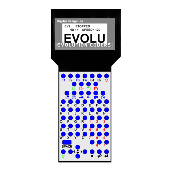
Digital Design Inc. Digital Design Inc. has a policy of continual product improvement. The Company therefore reserves the right to modify the information contained in this manual without prior notice. - Page 2 EVOLUTION CONTROLLER PRINT HEAD CABLE PLUG STOPPED HD 1<- - SPEED= 120 EVOLU GRAPHIC (WSYWIG) E V O L U T I O N C O D E R S LCD DISPLAY NOTE: THE EVOLUTION GRAPHIC CONTROLLER WILL CONTROL THE EVOLUTION 1 (EV1) EVOLUTION 2...
-
Page 3: Table Of Contents
INSTALLATION AND OPERATION MANUAL PART 1: INSTALLATION PROCEDURES INSTALLING THE EVOLUTION II PRINTING SYSTEM MOUNTING ON PRODUCTION LINE EVOLUTION II MOUNTING OPTIONS After the mounting bracket is configured loosen the locking collar 7A014S and re-locate it against the horizontal extension bracket and tighten. This allows the user to loosen the horizontal mounting bracket-locking knob and rotate the assembly without losing the height adjustment. - Page 4 3 – SET UNIT I.D.: 4 – LOAD CARD: SETTING PRINT DELAY AND LINE SPEED SETTING LINE SPEED SETTING PRINT DELAY SETTING HEAD ALIGNMENT INPUT, EDIT OR DELETE MESSAGES VARIABLE FIELD FORMAT PRINTING MESSAGE STORAGE STORING A MESSAGE RECALLING A STORED MESSAGE PART 3: MAINTENANCE PROCEDURES SHORT PERIODS OF SHUT DOWN LONG PERIODS OF SHUT-DOWN...
- Page 5 PROGRAMMING BAR CODES: BARCODE TECHNIQUES: BARCODE TYPES USING CHECK CHARACTER: EVOLUTION 1 SYSTEM MANUAL Issue 1.1 20 Dec 2006...
-
Page 6: Mounting On Production Line
INSTALLING THE EVOLUTION II PRINTING SYSTEM Caution should be taken while installing the EVOLUTION printing system on your equipment. Digital Design Inc. has taken every precaution to ensure a safe and accurate instruction set to guide the installer through the installation process. -
Page 7: Evolution Ii Mounting Options
EVOLUTION II MOUNTING OPTIONS The EVOLUTION II mounting bracket assembly C21010 has a number of possible mounting configurations, which allows adaptability to a variety of production equipment. cross slide bracket C20741 may be rotated loosening included setscrew 504JCS rotating the bracket. This allows the print head to be extended by just over 1”. -
Page 8: Horizontal Mounting Bracket-Locking Knob And Rotate The Assembly Without Losing The Height Adjustment
Vertical height adjustment for the EVOLUTION II print head is accomplished by loosening included hand knob 5993K41. Note that the hand knob may be mounted on either side horizontal mounting bracket depending orientation of the bracket. It should also be noted... -
Page 9: Grounding Strap Installation
GROUNDING STRAP INSTALLATION INSTALL STRAP UNDER 5/16” SCREW. ENSURE CONDUCTIVITY TO EARTH GROUND IS LESS THAN 1 OHM INPUT POWER CONNECTION AND MODIFICATION Insert the power plug to the available power source. The supplied power supply will is universal and will auto detect 100/240 VAC 50-60hZ. No other adjustments are necessary. -
Page 10: Installing The Print Cartridge
INSTALLING THE PRINT CARTRIDGE Remove the protective film from the face of the print head and retain the film. This protective film may be re-applied to store partially used cartridges. If it is necessary to remove the print head and store for a long period of time, it is best to re-apply the plastic film, and place the cartridge in a closeable plastic bag. -
Page 11: Connecting The Controller To The Carriage
CONNECTING THE CONTROLLER TO THE CARRIAGE Connect the Controller to the print carriage using the supplied 3 FT (.9 mm) interconnect cable C21008-3 supplied with the Printing System. The cable is a standard RJ50 (10 conductor). Longer cables are available as required. Connect either end of the cable to the Carriage Assembly and securely lock in place. -
Page 12: Configuring The Printer
The third line indicates the serial number of the printer SYSTEM RESET Soft Reset: There are two types of resets available in the Evolution II printing system. The first type of reset is a SOFT RESET. ERASE STORED Pressing the R key while applying power to the... -
Page 13: Hard Reset
Hard Reset: The second reset is a hard reset. Disconnect the power cable. Insert a standard paper clip into the hole on the female dovetail side of the cabinet, and while holding the paper clip in place (a light click will be felt) re-apply the power connector. -
Page 14: Multiple Print Heads
MULTIPLE PRINT HEADS EVOLUTION II printing systems have the ability to reside on a network. The network may contain from 1 to 32 print carriages connected via RJ50 cables. These cables are available in varying lengths depending on the application. -
Page 15: Evolution Ii Quick Start
EVOLUTION II QUICK START Connect the printer carriage to the appropriate STOPPED power source. HD 1- - >SPEED=100 Connect the controller to the carriage assembly. EVOLU The controller derives power from the carriage. On startup the LCD will display as pictured. -
Page 16: Entering A Message
ENTERING A MESSAGE Press the GREEN PRINT key EV2 STOPPED The LCD display will change from PRINTING to HD 1- - >SPEED=100 STOPPED. EVOLU Press the GREEN EDIT key MESSAGE ENTRY - - - - FONT-1 LINE EVOLU Press the BLUE F3 key to delete the entire MESSAGE ENTRY message... -
Page 17: Storing A Message
STORING A MESSAGE EV2 STOPPED Press the GREEN STOP PRINT KEY HD 1- - >SPEED=100 Note: There are a total of 100 messages stored in the hand held controller. This EXP 12/ allows the user to move the controller to another print station and enter the same or other saved message. -
Page 18: Loading A Message
LOADING A MESSAGE STOPPED Press the GREEN STOP PRINT KEY HD 1- - >SPEED=120 EVOLU MESSAGE # 1 EV2 Press the RED MESSAGE STORE key use the keys to select the desired EXP 12/ message and press the ENTER STOPPED HD 1- - >SPEED=120 EXP 12/ EV2 PRINTING... -
Page 19: Evolution Ii Quick Setup
EVOLUTION II QUICK SETUP Install a new cartridge. Press the following keys in order: To reset the ink level detector press REMAINING INK 100 % C NEW CARTRIDGE OTHER KEY EXIT Each time a new print cartridge is installed the system automatically profiles the correct operating parameters for the new cartridge. -
Page 20: Part 2: Operation Procedures
PART 2: OPERATION PROCEDURES OVERVIEW CONTROLLER AND LCD keypad print station, pictured here, contains 64 keys. The LCD will display various messages to assist in programming on the upper half EV2 STOPPED of the display. The lower half HD 1 - ->SPEED= 100 of the display will show up to two lines of the entered print EVOLU... -
Page 21: Keypad Key Descriptions
KEYPAD KEY DESCRIPTIONS This is the manual cycle key. When in the Stopped mode, pressing this key causes the printer to print one code This is the Print key. Use it to place the unit in the Print mode This is the Purge key. Use it to purge ink for maintenance purposes. The unit must be in the Command mode to use this key. -
Page 22: Turning On The Print Station For The First Time
TURNING ON THE PRINT STATION FOR THE FIRST TIME To turn the print station on insert the power jack into the DC power connector. STOPPED There is no on/off switch. HD1- - >SPEED=120 The first time the print station is turned on, as EVOLU received from the factory, the LCD will look like the illustration on the left. -
Page 23: Changing System Date And Day Of Week Codes
CHANGING SYSTEM DATE AND DAY OF WEEK CODES When the unit is in the STOPPED mode PRESENT SETTING ANY CHANGES Y/N pressing the DATE key allows the user to 01/04/00 change the system date. If there are no changes press the N key to return to the STOPPED mode. -
Page 24: Changing System Time And Date Roll Over Time
CHANGING SYSTEM TIME AND DATE ROLL OVER TIME TIME SETTINGS When the unit is in the STOPPED mode 1= SET TIME pressing the TIME key allows the user to 2= DATE CHANGE TIME change the system date. If there are no changes press the N key to return to the STOPPED mode. - Page 25 Similar to entering the time enter first the hours DATE TIME CHANGE then at the next prompt enter the minutes. ANY CHANGES Y/N Remember the time is entered in military time. 00:00 ENTER HOURS - Entering 06:00 sets the date change time at DATE TIME CHANGE 6:00AM.
-
Page 26: Programming
PROGRAMMING DEFINITIONS There are two parts to programming the EVOLUTION II ink jet printer, • Setting the operations parameters, (character width, delay, etc.) and • Building the message. MODES OF OPERATION The system operates is 3 basic modes. They are: PRINTING Mode, STOPPED (command) Mode, and MESSAGE ENTRY Mode. - Page 27 MENU STRUCTURE In the Command mode, access is allowed to the menu structure for basic parameters. The menus reside within the function keys, F1 through F4. In order to select one of the parameters, press the number key that corresponds to the desired parameter.
-
Page 28: Character Spacing
F1 MENU Place the unit in the Command mode and press 1=CHAR. SPACING 2=EXT. ENCODER . The screen shown to the left is produced. 3=DATE OFFSET Press the correct number to make changes to that 4=BARCODE TYPE parameter. Those selections designated as NOT AVAILABLE will not respond to selection. -
Page 29: Date Offset
< - - SELECT - - > entered into message. standard CODE 39 EVOLUTION II contains 8 barcode symbologies, which are: UPC-A, UPC-E, EAN-8, EAN-13, CODE 39, CODE 128B, CODE 128C AND INTERLEAVED 2 OF 5. < - - SELECT - - > UPC A... - Page 30 ADD MAN READABLE This parameter adds a man readable set of 1 = YES characters directly beneath the barcode being 2 = NO printed, and is valid for all barcode types. ADD GUARD BARS If man readable characters are enabled the user 1 = YES has the option of enabling or disabling guard 2 = NO...
-
Page 31: Direction
F2 MENU Place the unit in the Command mode and press 1=DIRECTION . The screen shown to the left is 2=PRINT INVERSE produced. Press the correct number to make 3=PRODUCT DETECT changes to that parameter 4=AUTO REPEAT 1 - DIRECTION: The arrow shown on the LCD’s third line screen <... -
Page 32: Auto Repeat
4 - AUTO REPEAT: This option enables the unit to continuously print < - - SELECT - - > repeated codes at specified time intervals along REPEAT TIME= 0 the entire length of the product. A time of 0 disables the Auto Repeat option. Use to change the repeat time. -
Page 33: Product Count
F3 MENU 1= PRODUCT COUNT 2= SHIFT CODE 3=DATE FORMAT 4=TIME FORMAT 1 – PRODUCT COUNT: The product counter is a non-printable entity, and must be read after the end of the set time PRODUCT COUNT period. The counter indicates each print cycle CHANGES Y / N OR C sensed by the external photo eye. -
Page 34: Shift Code
2 – SHIFT CODE: Shift codes may be encoded directly in the 1= PRODUCT COUNT printable message. The printer can print 6 2= SHIFT CODE individual shift codes. Each shift code contains a 3=DATE FORMAT unique start time and alpha/numeric code to be 4=TIME FORMAT printed. -
Page 35: Date Format
3 – DATE FORMAT: Press F3 to change the date formatting. Each of 1= PRODUCT COUNT the following screens prompts the user to enter 2= SHIFT CODE the desired format for printing. 3=DATE FORMAT NOTE: USER INDIVIDUALLY 4=TIME FORMAT CHANGE THE FORMAT OF BOTH THE CALANDER FORMAT DATE... - Page 36 Alpha characters may have bee selected by MONTH FORMAT pressing option 2. 1=NUMERIC 2=LETTERS DATE FORMAT Delete the current formatting by pressing the D=DAY M=MONTH Delete key. Y=YEAR jjjyy DATE FORMAT Enter the desired Date Format and notice when D=DAY M=MONTH the M (month) is selected the display shows Y=YEAR...
-
Page 37: Time Format
4 – TIME FORMAT: Change the Time Format by selecting option 4. 1= NOT AVAILABLE 2= NOT AVAILABLE NOTE: Delimiter characters like a : 3=DATE FORMAT code may be entered to separate fields 4=TIME FORMAT The factory default for time formatting is hh:mm TIME FORMAT and may be changed as required. -
Page 38: Language
F4 MENU Place the unit in the Command mode and press 1 = LANGUAGE . The screen shown at left is produced. 2 = INK SUPPLY 3 = SET UNIT I.D. Press the number that corresponds to the 4 = LOAD CARD parameter you wish to change. -
Page 39: Evolution 1 System Manual Issue 1.1 20 Dec
3 – SET UNIT I.D.: < - - SELECT - - > Each print carriage can contain a unique address SET HEAD # = 1 to distinguish multiple carriages when controlled by a single hand held controller or computer data link using an RS485 data link. -
Page 40: Load Card:
4 – LOAD CARD: LOADING FONTS (MENU SELECT 1) The user can replace the existing FONT, add up EXECUTE LOADER to six logos, or load optional software from a 1=LOAD FONTS Data Flash card, which is plugged into the top of 2=LOAD LOGOS the print carriage. - Page 41 LOADING LOGOS (MENU SELECT 2) The user can replace the existing FONT, add up EXECUTE LOADER to six logos, or load optional software from a Data 1=LOAD FONTS Flash card, which is plugged into the top of the 2=LOAD LOGOS print carriage.
- Page 42 WILL NOT OPERATE IN ANOTHER PRINT CARRIAGE. NOTE: There are four fonts loaded into the EVOLUTION II printer at any one time. Loading a new font will overwrite the existing font or fonts. Print starts at the bottom nozzle of the print head (dot 150 for line 2) and at the middle of the print head (dot 75 line 1).
-
Page 43: Setting Print Delay And Line Speed
SETTING PRINT DELAY AND LINE SPEED LINE SPEED – This setting adjusts the width of the printer message on the product. This setting should be adjusted to produce the desired print on the product. Line speed can be increased or decreased to stretch or compress the message to fit the desired print area. -
Page 44: Setting Print Delay
SETTING PRINT DELAY Print delay is used to position a message on the STOPPED product at a location other than at the leading edge. HD1- - >SPEED=100 Access this parameter by pressing on the keypad. EVOLU NOTE: This parameter may be set when the unit is either in the PRINTING or STOPPED mode PRINTING HD1- - >SPEED=100... -
Page 45: Input, Edit Or Delete Messages
INPUT, EDIT OR DELETE MESSAGES To input, delete or edit a message, the unit must be STOPPED HD1- - >SPEED=120 in the STOPPED Mode. If the LCD reads PRINTING, press The screen should be EVOLU similar to the one shown at the left. Enter the Message Entry mode by pressing MESSAGE ENTRY The top portion of the screen will change as shown... - Page 46 Continue to build the message or press to return to the Command mode. EVOLUTION II messages may contain up to 4 lines of text. Selecting multiple message lines is accomplished by pressing the font key until the appropriate line designation is displayed.
- Page 47 Enabling variable field programming requires the MESSAGE ENTRY use of the special function keys. - - - - FONT- 1 LINE To enter a date that automatically changes use MESSAGE ENTRY key. The current date format as set in the - - - - FONT- 1 LINE F3 menu is entered into the message.
- Page 48 Sequence number format is programmable in the SEQ. NUMBER STOPPED mode. The counter may be set to 1= COUNT UP count either up or down by selecting number 1 or 2= COUNT DOWN 2. Pressing enter advances the user to the next menu prompt.
- Page 49 Moving the cursor back over the various characters contained in the message may be used to validate the message. Note that the field designator will normally appear as - - - - indicating an alpha/numeric code as would be seen by moving the cursor under the M F G or the E X P on the second line.
- Page 50 The above constitutes 10 object fields. Even though there are 48 characters permitted per line data entry will be inhibited when the 15 object is entered, although the last field, if it is an alphanumeric object, may contain enough characters to meet the 48-character limit.
- Page 51 Barcode fields may be entered by pressing the MESSAGE ENTRY key while in the MESSAGE ENTRY mode. - - - - FONT- 1 LINE The barcode insignia is indicated following the font CODE 128C style and the code type is displayed on the third 12345 line of the display.
-
Page 52: Variable Field Format Printing
VARIABLE FIELD FORMAT PRINTING The EVOLUTION II printer provides the operator the capability of adding variable fields to a message. This includes TIME, DATE, SEQUENCE, DATE OFFSET and SHIFT CODE PRODUCT COUNT and BARCODES. Entering any of these special fields is accomplished with the keys. - Page 53 Enter the Message Entry mode by pressing MESSAGE ENTRY The top portion of the screen will change as shown FONT 1 LINE on the left. EVOLU The user has two options to edit or change a MESSAGE ENTRY message. If a new message is to be entered press FONT 1 LINE key to delete the entire existing message.
- Page 54 PASSWORD PROTECTION The printer contains a password function designed to limit access to the edit menu and prevent unauthorized changing of message PASSWORD XXXXX lines. To activate this function, switch the unit off, then press and hold while switching the unit on.
-
Page 55: Recalling A Stored Message
MESSAGE STORAGE STORING A MESSAGE The controller is able to store up to 100 system wide MESSAGE # 1 EV2 programmed messages their associated parameters. Follow these steps to store a message. Create the message and press Press . Using , scroll to the desired message location number. -
Page 56: Part 3: Maintenance Procedures
PART 3: MAINTENANCE PROCEDURES SHORT PERIODS OF SHUT DOWN When the printer has been shut down overnight, the system might require a purge to clear out dust particles that have settled on the nozzle area during non- use. This is only necessary if there are missing dots in the printed code on product. -
Page 57: Long Periods Of Shut-Down
CAUTION: USE THE ORIGINAL SEALING TAPE SUPPLIED WITH THE EVOLUTION II INK CARTRIDGE. DO NOT USE ANY OTHER MATERIAL OR ANY ADHESIVE BACKED PRODUCT, AS THIS WILL DAMAGE THE NOZZLE AREA. -
Page 58: Print Cartridge Maintenance
PRINT CARTRIDGE MAINTENANCE It is necessary to maintain the print cartridge free from accumulated dust and debris. Periodically the cartridge should be removed and cleaned. This is totally dependent on the operating environment and the average printable life of the ink cartridge. - Page 59 NOTE: Ingested air or severe nozzle clogs may be eliminated with the use of the cleaning syringe/tray ordered optionally. The photo below shows the correct procedure in using the syringe and cleaning tray. Insert the ink cartridge into the tray and securely snap into place. Place the tip of the syringe into the front of the tray.
-
Page 60: Print Carriage Maintenance
PRINT CARRIAGE MAINTENANCE It is necessary to maintain the print head carriage free from accumulated dust and debris. Periodically the print head carriage should be inspected and cleaned. This is totally dependent on the operating environment. In extremely dusty environments, this maintenance procedure may be required occasionally but on average every week should be sufficient. -
Page 61: Part 4: Troubleshooting And Repairs
PART 4: TROUBLESHOOTING AND REPAIRS FAULTS This chart was created to assist the user in troubleshooting the unit. Find the problem in the first column; apply the remedy(s) suggested in the third column. Condition Probable Cause Remedy LCD remains blank. No power. -
Page 62: Part 5: Parts List And Options
EVOLUTION II Controller PCB Assembly C30238 EVOLUTION II Controller Keypad C21002 EVOLUTION II Print Head Carriage Assembly C21002-7 EVOLUTION II Print Head Carriage CPU Assembly C21002-8 EVOLUTION II Print Head Carriage POGO Assembly C21005 EVOLUTION II Mounting Bracket Assembly C21000-2... - Page 63 4500YW6 6 Pack of Yellow Ink Cartridges 4500CY6 6 Pack of Cyan Ink Cartridges 4500UV6 6 Pack of Ultra Violet Ink Cartridges 4600BK6 6 Pack of Black Ink Cartridges (SEMI-POROUS) EVOLUTION 1 SYSTEM MANUAL Issue 1.1 20 Dec 2006...
-
Page 64: Part 6: Communications Protocol
PART 6: COMMUNICATIONS PROTOCOL This communication protocol covers all EVOLUTION products. Some commands are not applicable to certain units, and care must be taken in determining what valid commands are for a specific unit. Commands that reference specific units are so noted. ASCII CHARACTER CHART NUL SOH STX ETX EOT ENQ ACK BEL BS DLE DC1 DC2 DC3 DC4 NAK SYN ETB CAN EM... -
Page 65: Description
DESCRIPTION This communication protocol is based on Version 1.4, which was released NOV 2005 and is used with all EVOLUTION products. The communications option converses with a host computer via an RS485 data link. NOTE: EACH REQUEST OR COMMAND SENT TO A PRINT STATION RECEIVES A RESPONSE FROM THAT PRINT STATION. -
Page 66: Hardware Interface
HARDWARE INTERFACE When connecting multiple print carriages via an RS485 link, input and output connectors are provided on the print station, which allows the cabling to be daisy chained. NOTE: It is important to remember to set each of the print stations to a unique address. -
Page 67: Software Protocol
(0x2f) " (0x22) Cents (0x25) Solid block (0x3b) Ň (0x3f) Ě (0x40) Ó (0x7b} Logo 1 (0x7c) Logo 2 (0x7d} Logo 3 SOFTWARE PROTOCOL In the following pages, all references to characters or digits pertain to the standard ASCII character set. The bar (|) character is used as a field separator and it is not part of the transferred data. - Page 68 NAK 6 = Print station buffer full must print before next download to clear buffer. NAK 7 = NOT USED NAK 8 = NOT USED EVOLUTION 1 SYSTEM MANUAL Issue Issue 1.1 20 Dec 2006...
-
Page 69: Commands
Q. ESC|STX|Address|`!`|SOH|EOT R. ESC|STX|Address|{PRINTER fffffssss}|CR|EOT Where: PRINTER= ASCII string PRINTER for EVOLUTION I for EVOLUTION II EVSC for EVOLUTION SC fffff = Software and Firmware versions (eg. 2.02H indicates version 2.02 with Firmware version H) ssss = Optional Software loaded... - Page 70 0x6c Special Field Flags (EV II, EV SC AND EVI WITH OP1 AND ABOVE) Q. ESC|STX|Address|`l`|SOH|EOT R. ESC|STX|Address|`l`|`x`|`y'|EOT Where: x defines bits 7,6,5,4 Bit 7 = don’t care Bit 6 = dont care Bit 5 = 1 = No guard bars Bit 4 = 1 = Man read added to barcode Where: y defines bits 3,2,1,0 Bit 3 = 1 = Bar checksum added to barcode...
- Page 71 ‘G’ 0x47 Errors (note: error codes must be reset) (EV I, EV II, EV SC) Q. ESC|STX|Address|`G`|SOH||EOT R. ESC|STX|Address|`G`|'x`|`y'|EOT Where: x defines bits 7,6,5,4 Bit 7 = UART Overrun Error Bit 6 = Communication Overrun Error Bit 5 = UART Framing Error Bit 4 = UART Parity Error Where: y defines bits 3,2,1,0 Bit 3 = Font checksum error loading from card to chip...
- Page 72 0x31 Auto Repeat Inter-print delay (Range 0 - 255) (EV II, EV SC AND EVI with any option pack) Q. ESC|STX|Address|`1`|SOH|EOT R. ESC|STX|Address|`1`|`x`|`y`|EOT D. ESC|STX|Address|`1`|`x`|`y`|EOT X. ESC|STX|Address|`1`|ACK|EOT 0 = Auto Repeat Disabled Each count provides a delay equal to 16 columns for EV I and EV II. Each count provides a delay equal to 2 columns for EV SC.
- Page 73 0x3E Head Align (Range 0 - 16) 'O' on keyboard > (EV II only) Q. ESC|STX|Address|`>`|SOH|EOT R. ESC|STX|Address|`>`|`x`|`y'|EOT D. ESC|STX|Address|`>`|`x`|`y`|EOT ESC|STX|Address|`>`|ACK|EOT 0x34 Sequence Number Rollover Value (EV II, EV SC AND EV1 with version 2.09 and OP2 or 3) Q. ESC|STX|Address|`4`|SOH|EOT R.
- Page 74 ‘0’ 0x30 Shift Code (max 6 shift codes) (EV II, EV SC AND EVI WITH OP3) Q. ESC|STX|Address|`0`|SOH||EOT R. ESC|STX|Address|`0`|`hh mm`|{zz}|……|CR|EOT Where: each set of 2 ASCII characters represent the upper and lower nibble of a packed BCD byte …… = pattern repeat for each shift code programmed = shift start hours = shift start minutes = shift code to print...
- Page 75 SPECIAL FIELD OBJECTS Message Objects define special characteristics about the messages contained in line 1 or line 2. These may define for example font size, sequence number, date code, etc. There may be up to 15 Objects (special fields) for each line in a message with the limitation that there can only be 1 sequence number imbedded in a message.
- Page 76 Barcodes are also an object field and must be considered when entering a message. Thus a barcode with an imbedded sequence number is counted as two objects. EVOLUTION 1 SYSTEM MANUAL Issue Issue 1.1 20 Dec 2006...
- Page 77 'P' 0x50 Message Objects (continued) = font of object Where: for EV I AND EV II ff= 00 for 2 Line Font ff= 01 for 1 Line Font ff= 02 for 3 Line Font (EV II only) ff= 03 for 4 Line Font (EV II only) Where: for EVSC ONLY ff= 00 for S5 Font ff= 01 for S7 Font...
- Page 78 0x77 Line 3 Message (max 24 characters) (EV II only max 48 characters) Q. ESC|STX|Address|`$`|SOH|EOT R. ESC|STX|Address|`$`|{message}|CR|EOT D. ESC|STX|Address|`$`|{message}|CR|EOT X. ESC|STX|Address|`$`|ACK|EOT 0x7a Line 4 Message (max 24 characters) (EV II only max 48 characters) Q. ESC|STX|Address|`$`|SOH|EOT R. ESC|STX|Address|`$`|{message}|CR|EOT D. ESC|STX|Address|`$`|{message}|CR|EOT X.
- Page 79 'Q' 0x51 Starting Sequence Number (max. length 9 digits) (EV II, EV SC AND EV1 with version 2.09 and after) Q. ESC|STX|Address|`Q`|SOH|EOT R. ESC|STX|Address|`Q`|{zzzzzzzzz}|CR|EOT Where: zzzzzzzzz = ASCII string which is the starting sequence number to print. D. ESC|STX|Address|`Q`|{zzzzzzzzz}|CR|EOT X. ESC|STX|Address|`Q`|ACK|EOT '2' 0x32 Date and Time Setting / Reading (EV I, EV II, EV SC)
- Page 80 NOTE: THE FOLLOWING CODES ARE SPECIFIC TO EVOLUTION II ONLY ' " ' 0x22 Minimum Bar Width (Range 3-15 Data matrix 2-15) Default 5 Q. ESC|STX|Address|`"`|SOH|EOT R. ESC|STX|Address|`"`|`x`|`y`|EOT D. ESC|STX|Address|`"`|`x`|`y`|EOT X. ESC|STX|Address|`"`|ACK|EOT ' .' 0x2e Bleed Compensation (Range 0 - 3) Default 0 Q.
- Page 81 0x3F Barcode Name(read only) Q. ESC|STX|Address|`?`|SOH|`x`|`y`|`x1`|`y1`|EOT Where: `x``y` = Barcode type as in 'n' command `x1`|`y1` = don't care R. ESC|STX|Address|`?`|{BARCODENAME}|CR|EOT where BARCODENAME = Ascii name of type of barcode 0x3d Barcode Verify D. ESC|STX|Address|`=`|`x`|`y`|{BARCODESTRING}|CR|EOT x = don't care y = type of barcode ( same as 'n' command) BARCODESTRING = Barcode Ascii data X.
- Page 82 Example written in C to query a print station to determine the line speed. // Query Print Station Address 7 for Line Speed putchar(0x1b); // Send out ESC putchar(0x02); // Send out STX putchar(0x30); // Send out upper nibble of address 07 putchar(0x37);...
- Page 83 Example written in C to send a line speed to a print station // Send Print Head Address 2 Line Speed of 100 feet per minute. putchar(0x1b); // Send out ESC putchar(0x02); // Send out STX putchar(0x30); // Send out upper nibble of address putchar(0x32);...
- Page 84 Example written in VB to send a new message to a print station. Public Sub DoMessage() DATA$ = "800": GETINFODATA: Rem DISABLE PRINT MODE DATA$ = "&32": GETINFODATA: Rem SET LINE SPEED TO 50 DATA$ = "P01010010000100000000" & Chr$(&HD): GETINFODATA: Rem SET OBJECTs DATA$ = "%ABCDEFGHIJ"...
- Page 85 MsgBox MSG$ COMM.InBufferCount = 0: Rem FLUSH THE INPUT BUFFER End Sub THE ABOVE VB ROUTINES DEMONSTRATE THE ENTIRE SEQUENCE OF: PREPARING DATA TO SEND TO THE HEAD SENDING THE DATA TO THE HEAD WAIT FOR A RESPONSE DETERMINE IF THE DATA WAS ACCEPTED OR REJECTED EVOLUTION 1 SYSTEM MANUAL Issue Issue 1.1 20 Dec 2006...
-
Page 86: Option Jumper Descriptions
PART 7: OPTION JUMPERS AND CABLING OPTION JUMPER DESCRIPTIONS Factory default for all jumper settings is in the ON position. To remove a jumper in the OFF position place the jumper on a single pin for future use VSEL J7 This jumper when in the ON position supplies a +12vdc source on the RJ50 input connector. -
Page 87: Jumper Location
JUMPER LOCATION EXTERNAL ENCODER VOLTAGE SELECT ENSEL J9 VSEL J7 ON= PASS THRU ON= +12 OUTPUT OFF= FLOAT OUTPUT OFF= FLOAT OUTPUT EXTERNAL PRODUCT DETECT PRSEL J10 ON=PASS THRU OFF=FLOAT OUTPUT EVOLUTION 1 SYSTEM MANUAL Issue Issue 1.1 20 Dec 2006... -
Page 88: Option Cabling Descriptions
Connection to the optional control port requires an RJ50 connector. Below is an example of the external product detect eye supplied by DIGITAL DESIGN INC part number C21006. EVOLUTION 1 SYSTEM MANUAL Issue Issue 1.1 20 Dec 2006... - Page 89 For those applications requiring accurate line speed detection an external encoder is needed. The external encoder will provide accurate signals eliminating problems in those applications where moving product has an acceleration or deceleration component in its motion, and is often mandatory when trying to produce a reliable printed barcode.
-
Page 90: Part 8: Specifications
PART 8: SPECIFICATIONS PRINTER SPECIFICATIONS PRINT CHARACTERISTICS Character Set: Full alphanumeric and 20 special symbols Standard Font: Arial style Logos: up to 3 resident Line Speeds: From 10 to 200 fpm Encoder Ratio: 0 to 7 Print Delay: From 1 to 255 (approx .060 in to 15.0 in) Character Heights: 1/2”... -
Page 91: Default Settings
DEFAULT SETTINGS FUNCTION DEFAULT SETTING RANGE DIRECTION < < > FONTS ARIEL STYLE USER DEFINED INTER-CHARACTER 1 - 25 SPACING LANGUAGE ENGLISH ENGLISH / SPANISH LINE SPEED 10 - 200 LOGOS 1 - 3 PRINT INVERSE NORMAL NORMAL / INVERSE PRODUCT DETECT INTERNAL INTERNAL / EXTERNAL... -
Page 92: Appendix A – Producing Reliable Bar Codes
Bleed factors vary greatly depending on substrates. For example printing on virgin versus recycled corrugated cases. EVOLUTION II printers have the capability to adjust various parameters of the printed barcode to circumvent the inherent problems in producing a reliable printed barcode. -
Page 93: Programming Bar Codes
PROGRAMMING BAR CODES: BARCODE TYPE: This is the type of barcode to be used and only one type is valid per message. Valid types are: CODE 39 CODE128B CODE 128C INTERLEAVED 2of5 EAN13 EAN 8 UPC-A UPC-E DATA MATRIX (optional) MINIMUM BAR WIDTH: This parameter controls the number of columns in a narrow bar. -
Page 94: Barcode Techniques
BARCODE TECHNIQUES The following are actual scanned images of a UPC-A barcode (without man- readable or guard bars for clarity). These tests were produced on white coated corrugated. These are pictured here to help the user understand some of the important parameters in producing a reliable barcode. - Page 95 The picture at the right is an exploded view previous scanned image. Again notice the ink bleed and how it affects the ratio of the dark to the light bar widths. Using SPACE parameter gives the user the ability to minimize this effect.
- Page 96 The image below is a scanned image of two sample prints. The upper section of code is produced at 60ft/min matching the line speed, while with the second sample, the line speed was increased to 100 ft/min. It should be immediately apparent at the difference in the optical density between both prints.
- Page 97 Below is a scanned image of a typical application where there was an acceleration and deceleration component in the line movement. Notice how the bars grew from left to right then began to compress towards the normal at the right. Also apparent is the change in the optical density of the pattern. This was a totally unreadable code.
-
Page 98: Barcode Types
BARCODE TYPES The following is a short description of the supported barcode types: Each barcode type contains either 2 or 4 widths. This defines how many sizes or a light or dark bar exists in the code. CODE39: Code 39 is an alphanumeric bar code that can encode (2 widths) Numbers Upper case alphabet Special symbols... - Page 99 UPC-A: UPC-A encodes 12 characters (4 widths) Numbers only It includes a 1-digit system code (normally 0) 10 digits are the data characters Checksum digit If the Check Character flag is set the software will calculate the optional check character (modulus 10). EVOLUTION 1 SYSTEM MANUAL Issue Issue 1.1 20 Dec 2006...
- Page 100 7 times with various resolutions ranging from a 7x7 element to a 1x1 element. Even though it is conceivable to produce a 1x1 element, the nature of ink bleed makes it unrealistic. The EVOLUTION II with the optional DATAMATRIX symbologies installed limits the element size to a 2x2 array.
- Page 101 As a comparison the following is a scanned image of the actual printed sample. IDEAL ELEMENT WITHOUT BLEED The above is an enlarged pictorial of the last 3 element resolutions. As may be seen the 2x2 element is extremely discernable, where the 1x1 array loses definition due to bleed patterns.
-
Page 102: Using Check Character
USING CHECK CHARACTER: If you are supplying the code with the check digit already calculated, you must deselect the ADD CHECK CHARACTER. If you want the software to calculate the checksum for you, you must select ADD CHECK CHARACTER. For example: EAN and UPC have fixed length and therefore only have the following possibilities exist.
Need help?
Do you have a question about the EVOLUTION II and is the answer not in the manual?
Questions and answers