Table of Contents

Summary of Contents for S/C Black BLK-IPE101
-
Page 1: User Manual
® H.264 Network Video Encoder User Manual Product: BLK-IPE101 Please read this manual before using your encoder, and always follow the instructions for safety and proper use. Save this manual for future reference. BLK-IPE101_PM... -
Page 2: Legal Notice
LEGAL NOTICE SC Black is a registered trademark of Supercircuits, Inc. Supercircuits products are designed to meet safety and performance standards with the use of specific Supercircuits authorized accessories. Supercircuits disclaims liability associated with the use of non- Supercircuits authorized accessories. -
Page 3: Table Of Contents
Table of Contents Features. . . . . . . . . . . . . . . . . . . . . . . . . . . . . . . . . . . . . . . . . . . . . . . . . . . . . . . . 2 SECTION 1 1 .1. -
Page 4: Features
SECTION 1: FEATURES SECTION 1 Features The SC Black BLK-IPE101 is a professional, premium-grade, state-of-the-art encoder designed for indoor installation in networks where exceptional video and audio quality is required with minimal bandwidth and storage available. Features include: H.264, MPEG-4, and MJPEG real-time encoding at D1 •... -
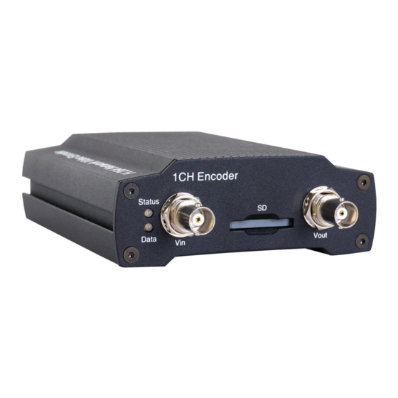
Page 5: Front.panel.indicators.and.connectors
SECTION 1: FEATURES 1.1 Front panel indicators and connectors Table 1. Status and Data LEDs indications Status Data Item Power OFF System initialization Blinking Dark Orange In Process Orange Normal State Orange Dark Orange Abnormal State Kernel booting up Orange Green In Process Orange... -
Page 6: Back.panel.connectors
SECTION 1: FEATURES 1.2 Back panel connectors BLK-IPE101 encoder back panel Connect to a USB device (or USB hub) for external storage. Ethernet RJ-45 LAN connector for 10/100Base-T Ethernet. This connector accommodates PoE. Pin block Terminal for audio output/input, alarm out, sensor in, and RS-232/RS-485 serial devices Reset Reset switch for restarting the encoder, or resetting the encoder to factory default settings. -
Page 7: Installation.and.setup
SECTION 2: INSTALLATION AND SETUP SECTION 2 Installation and Setup 2.1 What’s in the box Your encoder includes the following: BLK-IPE101 encoder • 12 V DC power adapter • 9-pin terminal blocks (2) • Hardware installation kit including mounting brackets (2), screws (4), and wall inserts (2) •... - Page 8 At the command prompt, enter ipconfig. The PC will display Ethernet data associated with your Ethernet adapter LAN connection. Example: Typical use of ipconfig in Windows XP Enter the IP Address, Subnet Mask, and Default Gateway for your PC’s Ethernet adapter into Table 2. www.sc-black.com...
- Page 9 SECTION 2: INSTALLATION AND SETUP The Ethernet adapter data you see by using ipconfig will probably be different from that shown in the example above. If you are using Windows Vista or Windows 7, the IP address NOTE is identified as the “IPv4 Address.” Table 2.
-
Page 10: Check.lan.for.default.ip.address.compatibility
2.4 Check LAN for default IP address compatibility Because all SC Black cameras and encoders are factory configured with the static IP address 192.168.0.100, check the LAN before connecting your encoder to ensure that network conflicts won’t occur. -
Page 11: Install.ipadmin.tool
SECTION 2: INSTALLATION AND SETUP At a Microsoft Windows computer attached to the LAN subnet where the encoder will be connected, open a Command Prompt window and enter: ping 192.168.0.100 The “Request timed out” response indicates that the IP address is not in use and the encoder can be attached to the network without causing errors. -
Page 12: Install.the.encoder
Connections to the encoder for audio in and out (microphone and speaker), D/I sensor, alarm, video out BNC, RS-232C, and RS-485 control are made through two 9-pin terminal blocks. The two 9-pin terminal block may be detached from the encoder. Install the two blocks into the connectors on the back of the encoder. www.sc-black.com... - Page 13 SECTION 2: INSTALLATION AND SETUP 9-pin terminal block Terminal block pin assignments 2.7.1 Audio in/out connections The encoder includes an interface for a mono audio input (from a microphone) and a mono audio output (to a speaker). The audio output is a low level signal that requires an amplified speaker (see Specifications).
- Page 14 The configuration of the sensor input wiring is illustrated in the diagrams below. Do not exceed the maximum input voltage or the relay switching rate. Refer to specifications in this manual for more information. CAUTION Voltage type sensor wiring schematic Relay type sensor wiring schematic www.sc-black.com...
- Page 15 SECTION 2: INSTALLATION AND SETUP To connect a sensor to the encoder: Route sensor wiring to the encoder. Strip 1/4” of insulation from one sensor’s sense and ground wires and insert them into the upper terminal block in the DI ch 1 and DI GND pin locations, respectively. Strip 1/4”...
- Page 16 The RS-232C encoder interface can be connected to some devices, such as a Point of Sale (POS) terminal. The wiring signal polarity and ground to the upper terminal block are shown in the schematic below. RS-232C device wiring schematic www.sc-black.com...
-
Page 17: Configure.the.encoder.ip.address
SECTION 2: INSTALLATION AND SETUP To connect an RS-232C device wiring to the encoder: Route wiring from the RS-232C device interface to the encoder. Strip 1/4” of insulation from TX, RX, and GND wires from the device and insert them into the upper terminal block RS-232C TX, RS-232C RX, and RS-232C GND pins, respectively, as shown in the schematic above. - Page 18 SECTION 2: INSTALLATION AND SETUP SC Black IP encoders and cameras it supports that exist on the network. The discovery process may take a few minutes. IPAdmin Tool discovering 192.168.0.100 In the Product Name list, find the entry with the same MAC address as the encoder you installed. If the encoder is not shown, click Refresh repeatedly to update the list.
-
Page 19: Setup.the.encoder.basic.configuration
SECTION 2: INSTALLATION AND SETUP Click SETUP. A Login window will open. In the Login window, enter the ID and PW (password) for your camera and click Login. The default administrator values for the ID and PW are root and pass. After entering ID and PW, the IP Setup window closes. - Page 20 In the camera window, click the SETUP link in the upper right corner of the window. Enter the User name and Password for the camera, and click OK. The default administrator values are root and pass. The Basic Configuration window will open. www.sc-black.com...
- Page 21 SECTION 2: INSTALLATION AND SETUP Under the Basic Configuration menu, click Date & Time. In the Date & Time Setting options: Select the Time Zone you prefer. Select the synchronization method, or Set Manually bullet and enter the appropriate information. H.264 Network Video Encoder...
- Page 22 In the User List, click root, and then click Modify and follow the prompts. Setup the root user with a new password and click OK. In the Users menu, click Apply, then click OK to restart the webserver (if you wish to do so at this time). www.sc-black.com...
-
Page 23: Image Quality Adjustments
SECTION 2: INSTALLATION AND SETUP 10. Click Add to include other administrators, operators or viewers to the user list. Follow the screen prompts to complete the entries. 11. Click VIEW in the upper right corner of the window to return to the camera live view. 2.9.1 Image quality adjustments Adjustments to the image brightness, contrast, hue, saturation, and sharpness are performed through the web browser:... - Page 24 From the VIEW window, click: SETUP > Event Configuration > DI On the Publisher DI screen, enable the DO devices for the sensor input (DI). Configure the Subscribe Email, Multicast, TCP, and other settings as needed. Click Apply. Under the Event Configuration Menu, click DO. www.sc-black.com...
-
Page 25: Final.installation.checks
SECTION 2: INSTALLATION AND SETUP Configure the Subscribe Email, Multicast, and TCP settings as needed. Click Apply. Click VIEW to return to the normal viewing window. 2.10 Final installation checks During final installation checks, the audio system, sensors and reporting devices, and the RS-485 connection are checked. - Page 26 Use a microphone at your PC to send audio to the camera speakers. Verify that your microphone audio is heard at the speaker. To adjust the speaker volume go to the Bi-directional Audio Settings menu. In the Talk to frame, adjust the volume to the preferred level. Click Apply. www.sc-black.com...
-
Page 27: Cleaning
SECTION 2: INSTALLATION AND SETUP At each (DI) sensor, cause a condition that would be produce an alarm condition. Verify that the alarm reporting (DO) device indicates the alarm, and that the alarm is reported as configured through the browser. If an RS-485 device was connected to the encoder, use the browser PTZ button and verify the RS-485 connection. -
Page 28: Specifications
Power over Ethernet Support - IEEE 802.3af class 0 (optional) Operating Temperature 32˚F ~ 122 ˚F (0 ˚C ~ 50 ˚C) Operating Humidity Up to 85% RH (non-condensing) Dimension 4.07” (W) x 1.48” (H) x 5.57” (D) Weight 0.85 lbs. www.sc-black.com... - Page 29 SECTION 3: SPECIFICATIONS Table 4. Video Content Analysis (optional) VCA Presence High Performance Advanced Tracking Algorithm, Low False Alarm Rate Easy to Use Intuitive Web Browser Interface Detection Zones Multi-segment Polygons and Lines On-screen Display Real-time Display of Tracking Data and Events VCA Surveillance Detection Behavior Direction, Stopping, Loitering, Entering, Exiting, Appear, and Disappear Filters...
-
Page 30: Appendix A Troubleshooting
IP address – reset to 192.168.0.1 • Subnet mask – reset to 255.255.0.0 • Gateway – reset to 192.168.0.1 • User ID – reset to root • Password – reset to pass • To force the encoder to the factory network settings: www.sc-black.com... -
Page 31: Check.firmware.version
APPENDIX A: TROUBLESHOOTING Disconnect the power (adapter) from the encoder. While pressing and holding down the reset button, power on the encoder. Release the Reset button 5 seconds after applying power. Wait for the encoder to reboot. A.3 Check firmware version Firmware is software embedded in the encoder that determines many of its features and functionality. -
Page 32: Appendix B Dimensions
APPENDIX B: DIMENSIONS APPENDIX B Dimensions www.sc-black.com... -
Page 33: Power.over.ethernet
APPENDIX C Power over Ethernet The BLK-IPE101 encoder supports Power over Ethernet (PoE) in conformance with the IEEE 802.3af standard. IEEE 802.3af allows for two power options for Category 5 cables. The PoE module signature and control circuit provides the PoE compatibility signature and power •... - Page 34 www.sc-black.com...
Need help?
Do you have a question about the BLK-IPE101 and is the answer not in the manual?
Questions and answers