Table of Contents
Advertisement
Quick Links
SERVICE MANUAL
Date
Revise Version
2005/8/30
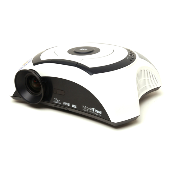
Model Name : DV-10
V1.0
Initial Issue
Copyright August, 2005 . All Rights Reserved
Prepared by SI :
________________________________________
Prepared by TSE :
________________________________________
Checked by :
________________________________________
Approved by :
________________________________________
Description
Advertisement
Table of Contents

Subscribe to Our Youtube Channel
Related Manuals for Optoma DV-10


Summary of Contents for Optoma DV-10
-
Page 1: Service Manual
SERVICE MANUAL Model Name : DV-10 Prepared by SI : ________________________________________ Prepared by TSE : ________________________________________ Checked by : ________________________________________ Approved by : ________________________________________ Date Revise Version Description 2005/8/30 V1.0 Initial Issue Copyright August, 2005 . All Rights Reserved... - Page 2 Preface This manual is applied to DV-10 0.55” DMD XGA digital projection system. It’ s the mode of single Panel, 180 Watt Compact P-VIP Lamp and 854(H) x 480(V) resolution. The manual gives you a brief description of basic technical information to help in service and maintaining the product.
-
Page 3: Table Of Contents
Function Test and Alignment Procedure Test Equipment Test Condition Test Display Modes and Pattern Inspection Procedure Calibration Guide to Entering Service Mode and Factory Reset Chapter 5 Firmware Upgrade Procedure Equipment Needed Hardware Setup Procedure Firmware Progarm Installation Procedure Firmware Upgrade Procedure DV-10... - Page 4 Chapter 6 EDID Key-in Procedure Equipment Needed Setup Procedure DDC Key-in Procedure Chapter 7 DV-10 DVD Code Installation Procedure DVD Region Code Setup Procedure Appendix A Exploded Overview Appendix B 7-32 PCBA Code Definition 7-32 Appendix C 7-33 Serial Number System Definition 7-33 Reader’...
-
Page 5: Chapter 1 Introduction
Half height DVD Meca + SOC DVD Module Half Height top loading DVD traverse One SOC for MPEG decoder and DVD servo Direct interlace, digital video output from MPEG decoder to Scaler ITU-R 656 YUV (4:2:2) Digital audio out and one subwoofer out DV-10... -
Page 6: Mechanical Spec
Number of active dots : 854(H) x 480(V) Electrical Specifications Power Supply Universal 100~240 VAC+/-10%, 50-60 Hz with PFC input For DV-10 , AC100V+/-10% (50-60 Hz) only. Power consumption 275W +/- 10% (Operating) 230W +/- 10%(ECO) 14W(Stand by) I/O ports & Inputs signals... - Page 7 7 keys for projector and 6 keys for DVD IR Remote Controller Top of the minus side battery spring should be directed to inside of cabinet. Top of the plus side battery spring should be lower than the libs of cabinet. DV-10...
- Page 8 6 main items ( Image-I, Image-II, Display, System, Language, Lamp Setting) Projection lens f = 28.3 ~ 38.2 mm, F/3.4, 1.1X. Projection Image Size 21” to 282” Diagonal Throw Distance 3.28 ft to 32.80 ft/ 1.0m to 10m Offset 154% = H’ /H 120% with extension feet. DV-10...
- Page 9 Throw Ratio: 1.25~1.5 (Projection Distance/Image Width) DV-10...
- Page 10 C -- 60 C , 0 - 80 %RH (Max.), non-condensing Acoustic noise level typical : 35dB(A)/Normal mode. typical : 32dB(A)/Low mode. noise measurement: Follows ISO 7779, A-weighted sound pressure level measurement 7200 rpm color wheel rotation and with DVD operation. DV-10...
- Page 11 Contrast, brightness, saturation, tint, sharpness, gamma adjustment open up Code for turning on/off region all, this feature is for engineer testing only and won’ t be release to end-user. Function Compatible - This player is compatible with DVD, VCD, SVCD, HDCD, CD, CD-R DV-10...
- Page 12 Multiple angles for viewing - With this player, you may enjoy DVD discs with views of different angles. (Provided the DVD disc has a Multi-angle feature embedded in it). Multiple picture proportion mode - With this player, you can select different picture modes to match the projector screen, according to the picture requirement. Regulation DV-10...
-
Page 13: Compatible Modes
Compatible Modes Analog Note: “*” means “compressed”. DV-10... -
Page 14: Chapter 2 Disassembly Of Procedure
Equipment Needed Long Nose Nipper (Left) Angle Cutting Nipper (Right) Hex Sleeves 5mm (Top) Screw Bit (-) 101 Screw Bit (+) : 107, 102, 101 (from top to bottom) Wrench (8mm) Nipper Appearance The Front Side The Rear Side DV-10... -
Page 15: Remove Lamp, Dvd Module And Control Keypad Board
*Note: please follow the direction shown in pink, first right and upward. DVD Cover Spring DVD Cover Step2: Turn unit facedown, unscrew one screw to remove Lamp Cover. Step3: Unscrew two screws to pull out Lamp Module. Step2 Lamp Cover Step3 Lamp DV-10... - Page 16 Step4: Uncrew two screws and unplug three wires shown in yellow to take off DVD Module. DV-10...
- Page 17 Step5: Unscrew nine screws and unplug one wire to remove DVD Loader Module. Step6: Unscrew four screws to remove DVD Keypad Board, Keypad Rubber and Damping Gear. Damping Gear Keypad Rubber Projector K e y p a d Board DV-10...
-
Page 18: Remove Top Cover, Speaker, Keypad Board, Rear Cover, Fan Module, Main Board And Audio Board
Cover, Fan Module, Main Board and Audio Board. Step1: Unscrew eight screws and unplug two wires to remove Top Cover. The obverse side. The reverse side Step2: Unscrew seven screws to remove Speakers and Keypad Board. Speakers Top Cover Keypad Board DV-10... - Page 19 Step3: Unscrew five screws to remove Shielding. Step4: Take off Rear Cover and Air Duct directly. Rear Cover Step5: Unscrew three screws, five hex srews and uplug nine wires to remove Main Board and Audio Board. DV-10...
- Page 20 Step6: Unplug two connectors to separate Audio Board from Main Board. Audio Board Main Board Step7: Unscrew two screws to remove Air duct Module. Air duct Module Step8: Take off Rear Cover and Air Duct directly. Fan Module DV-10...
-
Page 21: Remove Lamp Driver, Lvps, Engine, Color Wheel
Lamp Driver Holder Lamp Driver Step2: Unscrew five screws and unplug four wires to remove LVPS. The obverse side of LVPS The reverse side of LVPS Step3: Unscrew one screw to separate Shielding and Mylar from LVPS. LVPS Shielding Maylar DV-10... - Page 22 Step4: Unscrew seven screws and tear one tape off to remove Engine. Step5: Remove Fan Module directly from Engine and unscrew one screw to remove Thermal Switch. Step1 Step2 Fan Module Thermal Switch Step6: Unscrew one screw to remove Color Wheel. Color Wheel DV-10...
-
Page 23: Remove Dmd Board, Dmd Chip, Thermal Board,Front Cover, Elevator Module And Keypad Board
Remove DMD Board, DMD Chip, Thermal Board, Front Cover, Elevator Module and Keypad Board. Step1: Unscrew four screws and four hex screws to remove Heat Sink, DMD Board and DMD Chip. Step2: Unscrew three screws to remove Thermal Board and Interrupt Switch. 2-10 DV-10... - Page 24 Step3: Unscrew six screws to remove Base Buttom, Shielding and Buttom Shielding. Front Shielding Shielding Base Buttom Buttom Shielding Step4: Unscrew one screw to remove Front Cover and take off IR Sensor Board directly from Front Cover. IR Sensor Board Step5: Separate Elevator and Buttom Cover. Elevator Module 2-11 DV-10...
-
Page 25: Chapter 3 Troubleshooting
- Ensure that all connectors are securely connected and aren’ t broken - Check LVPS - Check Lamp Driver - Check Main Board Auto Shut Down - Check LED Status Lamp LED lit on - Check Lamp - Check Lamp Driver DV-10... - Page 26 - Check Main Board Image Flicker - Do “Reset(All data)” of the OSD Menu - Ensure that the signal cables and source are work as well - Check Lamp Module - Check Color Wheel - Check DMD Board - Check Main Board DV-10...
- Page 27 - Check DMD Board Disk cannot be read - Check if the disk is scratched. - Check if the anti-static protection of DVD Loader Module is unsoldered. - Check if the region code is correct or not. - Check DVD Loader Module. DV-10...
-
Page 28: Test Equipment
Circumstance Brightness : Dark room less than 2.5 lux. Inspection Distance : 1.5m~3m for functional inspection Screen Size : 60 inches diagonal (wide) After repairing each DV-10, the unit should be burn-in (Refer to the table below). Symptom Burn-in Time... -
Page 29: Test Display Modes And Pattern
The unit can't accept the leakage is Figure Light Leak Gray 10 brighter than Gray 10 pattern Figure HDTV 94% White No discolor ADC Calibration Calibration Calibration Pattern should be in full Figure (PC Calibration) Pattern screen mode DV-10... - Page 30 Figure 1. Fine Line Moire Figure 2. 64 RGBW Scale Figure 3. Red Pattern Figure 4. Green Pattern Figure 6. Full White Figure 5. Blue Pattern Figure 8. Gary 30 Pattern Figure 7. Full Black DV-10...
- Page 31 Figure 9. Blue 60 Pattern Figure 10. Text Pattern Figure 12. Gary 10 Pattern Figure 11. Boundary Frame Figure 13. 94% white Figure 14. Calibration Pattern DV-10...
-
Page 32: Inspection Procedure
If not, readjust by following steps. Select “Frequency” function to adjust the total pixel number of pixel clock in one line period. Then select “Tracking” function and use right or left arrow key to adjust the value to minimize video flicker. DV-10... - Page 33 Please check and see if it’ s in normal condition. If not, please return the unit to repair area. Please check and see if there are dead pixels on DMD chip The total numbers and distance of dead pixels should be complaint with the spec. DV-10...
-
Page 34: Calibration
-If not, please return the unit to repair area. (2) Dark Pixel : Test Pattern : Full White Pattern -Please check and ensure that the pixel number should be smaller or amount to 6 pixels -If not, please return the unit to repair area. DV-10... -
Page 35: Guide To Entering Service Mode And Factory Reset
Please enter the service mode, and then choose “Factory Reset” then choose “YES” and press enter to see if it works. This action will allow you to erase all end-user’ s settings and restore the original setting. DV-10... -
Page 36: Firmware Upgrade Procedure
- DLP Composer - DV-10 Firmware Hardware : - Power Cord - USB Cable - PC or Laptop - DV-10 Projector Hardware Setup Procedure Connect USB Cable of PC to USB port of DV-10 Projector. USB Cable USB Port DV-10... -
Page 37: Firmware Progarm Installation Procedure
Firmware Progarm Installation Procedure 5-3.1 DLP Composer Lite Setup Procedure Choose “DLP Composer Lite v3.6 Setup” program. Click “Next” button. DV-10... - Page 38 Reading the “License Agreement” rules, choose “I accept and agree to be bound by all the terms and conditions of this License Agreement” icon, then click “Next” button. DV-10...
- Page 39 Click “Next” button. Choose “All” icon, then click “Next” button. DV-10...
- Page 40 Click “Next” button. The program is executing “Initializing” status. DV-10...
-
Page 41: Usb Driver Upgrade Procedure
2. Plug power code and keep to hold “Menu“ button till the “TEMP”, and “LAMP” LED light turn to red. Press the button and hold it Execute the C:\Program files\DLP Composer\usbupdata.cmd. Note : The “DLP Composer” program must be closed first. DV-10... - Page 42 Type any key to continue. Then wait about a minute. Click “OK”. The USB driver updated successfully. DV-10...
- Page 43 Right click “My Computer” on the desktop. Select “Properties” on the popup menu to launch the “System Properties” window. Choose “Hardware” and then click “Device Manager.” Click “Jungo” to assure “DDP2000” and “WinDriver” are properly installed. If not, repeat Step 1 ~ 6. Device Manager DV-10...
-
Page 44: Firmware Upgrade Procedure
Firmware Upgrade Procedure Press “Menu“ button on projector, and hold it and plug power code and keep to hold “Menu“ button till the “TEMP”, and “LAMP” LED light turn to red. Execute the “DLP Composer ” file. Click “Edit” and “Preferences”. DV-10... - Page 45 Click “Library”. The library path located to the default installation directory is : C:\Program Files\DLP Composer. If not then press “Browse” to select the right path. Select “Edit\Preferences\Communications”, choose “USB”, and then click “OK”. Note : Vendor : 0x451 Product: 0x2000 5-10 DV-10...
- Page 46 Note : If appears the error message “cannot open USB driver - No projectors found”. Please unplug the USB cable and replug, then do step (4) again. If it stiill fails, please restart PC and redo 5-3.2 USB driver upgrade procedure. 5-11 DV-10...
- Page 47 If the firmware is ready, then click “Start Download” to process the firmware upgrade. Click “Yes” to erase the flash memory. 5-12 DV-10...
- Page 48 After file was download. DV-10 will be back to standby status automatically (Power LED flash blue). Please to restart the unit and enter the Service mode to check the F/W version of DV-10 . Note Ver.OO6 2005.07.05 Burn in Mode...
-
Page 49: Edid Key-In Procedure
Chapter 6 EDID Key-in Procedure Equipment Needed PC or Laptop EDID Fixture Power Adapter RS-232 Cable (Female to Male) VGA Cable DVI Cable Power Cord DDC Driver DV-10 Unit RS-232 Cable (F-M) DVI Cable EDID Fixture Power Adapter VGA Cable DV-10... -
Page 50: Setup Procedure
Step2. Connect P1 of the fixture with COM1 of PC/Laptop by RS232 cable. Step3. Connect P2 of the fixture with VGA port of DV-10 by VGA cable. Step4. Plug Power Adapter to the fixture and connect the DV-10 Power Cord. -
Page 51: Ddc Key-In Procedure
DDC Key-in Procedure Step 1. Execute “EDID” program. Step 2. (1) Check the Com port is “COM1” (2) Click the “Model” item (3) Choose the source file “OPTOMA_DV10_EDID_A.ini” and then open it. DV-10... - Page 52 (2) In “Write Source Select” Item, select “VGA”. (3) Check the COM port is COM1 (4) Click “Program” button. Step 4. “Please change the cable to VGA” message is shown on the screen, then click “OK” button. Notice : “RUN” message will appear on the screen. DV-10...
- Page 53 Step 5. When the DV-10 EDID program is finish, the “OK” message will appear on the screen. Step 6. (1) Make sure to check “Analog” and “Trans” in Read item (2) press “Read” button. (3) EDID Informations will show the result.
-
Page 54: Dv-10 Dvd Code Installation Procedure
Chapter 7 DV-10 DVD Code Installation Procedure DVD Region Code Region 1 - America Region 2 - Europe, England, Japan Region 3 - ROW, Taiwan, Hong Kong Region 4 - South America, Australia Region 5 - Pan-EMEA, Indian Region 6 -... - Page 55 Note : If you don’ t have the CD, please do the following steps. (1) A CR-RW Burner to make CD is needed. (2) Make sure that file name in the CD must be dvdrom.bin. Figure 2 Figure 3 Figure 4 DV-10...
- Page 56 Figure 3 again. If so, please do DVD code installation procedure again and do open the cover promptly when the image returns to Figure 1. Step 5. Press 1,2,3 and 4 on the remote control to check if the DVD code is correct or not. Figure 5 DV-10...
-
Page 57: Appendix A Exploded Overview
Appendix A Exploded Overview DV-10 Unit DV-10... - Page 58 FRONT SIDE PANEL PC+ABS, GE C6200 DV10 "GREEN" 51.81R12G001 LAMP COVER PC+ABS C6200 DV10 "GREEN" 61.00018G002 LOCK SCREW PAN MECH M3*8.5-3.5 BLACK "GREEN" 61.00073G001 HEX SCREW L=6mm M3*M3 CU DV-10 "GREEN" 75.81R15G001 BUY ASSY BOTTOM COVER MODULE DV10 "GREEN" 70.81R07G001 ASSY TOP COVER MODULE DV10 "GREEN" 70.81R08G001 ASSY FRONT COVER MODULE DV10 "GREEN"...
- Page 59 Top Cover Module DV-10...
- Page 60 Exploded Parts List Item Description 85.WA123.080 Screw Pan Tap M3x8 61.81R25G001 DVD UP COVER LOCK SUS 301 DV-10 "GREEN" 80.81R06G001 PCBA PROJECTOR KEYPAD BD FOR DV10 "GREEN" EMI GASKET CONDUCTIVE SPONGE 4.0(t)* 10.0(w)*17.0(l) 41.81R10G001 DV10 52.81R04G001 SPEAKER DAMPER SILICON RUBBER DV-10 "GREEN"...
- Page 61 III. Engine Module DV-10...
- Page 62 DMD HEAT SINK AL1070 VULCAN-1 61.80J48G001 DMD HEATSINK BACKER PLATE 739 AL6061 61.88608G.001 DMD HEATSINK SPRING PLATE SUS301 61.88611G.001 DMD SCREW IVYOX "GREEN" 80.80N02G.001 PCBA SMS BD FOR EP739 70.81R02G001 ASSY SUB ENGINE MODULE D10 "GREEN" 51.80W44G001 8*10*0.5t MYLAR FOR 2300MP "GREEN" DV-10...
- Page 63 M/B MYLAR FRPP DV10 "GREEN" 42.81R02G002 W.A. 7P #28 150mm UL1007 M/B TO DVD BD DV10 "GREEN" 80.81R07G002 PCBA AUDIO BD FOR DV10 "GREEN" SPEAKER EXTENTION CABLE RIGHT 135mm (RED) DV10 42.81R06G001 "GREEN" 41.81R08G001 EMI GASKET TAPE t=0.25mm DV10 DV-10...
- Page 64 Sub Engine Module DV-10...
- Page 65 85.1A526.060 SCREW PAN MECH M2.6*6 Ni NYLOK 85.1A626G040 SCREW PAN MECH M2.6*4 BLACK NYLOK "GREEN" 85.1F126G060 SCREW PAN MECH W/SF M2.6*6 Ni "GREEN" 75.80W15.004 BUY ASSY ZOOM RING STOP MDULE 2300MP 85.3A126.040 SCREW CAP HEAT D7.0 MECH M2.6*4 Ni DV-10...
- Page 66 W.A. 20P #24 200mm UL1007 LVPS TO DVD/B 6P MAIN/B 16P 42.81R01G001 Y CABEL DV10 "GREEN" 42.81R09G001 W.A. 2P #20 200mm LVPS/BALLAST DV10 "GREEN" W.A. #28 2P LIMITE SWITCH EXTENTION CABLE 140mm 42.81R13G001 DV10 "GREEN" 75.81R01.001 ASSY QUASAR LVPS DV10 KLIXON YS11 THERMAL SWITCH,WIRE 43.80S01G001 LENGTH:2205mm,125C 7-10 DV-10...
- Page 67 61.81R06G001 M/B STAND BRACKET AL 5052 t=1.0 70.81R01G001 ASSY ENGIVE MODULE DV10 "GREEN" 70.81R15G001 ASSY BOTTOM BASE MODULE DV10 "GREEN" 85.1F123.060 SCREW PAN MECH W/SF M3*6 Ni 41.81R10G001 EMI GASKET CONDUCTIVE SPONGE 4.0(t)*10.0(w)*17.0(l) 41.81U02G001 EMI TAPE W40*L40mm "GREEN" 7-11 DV-10...
- Page 68 VIII. DVD Module Exploded Parts List Item Description 70.81R11G001 ASSY DVD COVER MODULE DV10 "GREEN" 70.81R12G001 ASSY DVD LOADER MODULE DV10 "GREEN" 85.WA123.080 SCREW PAN TAP M3*8 SCREW PAN TAP TAPE 3M J350 17*60mm M3*8 7-12 DV-10...
- Page 69 VIIII. DVD Cover Module 7-13 DV-10...
- Page 70 DVD KEYPAD BUTTOM SILICONE RUBBER DV10 "GREEN" 51.81R20G001 DVD METAL DOME DV10 "GREEN" 80.81R05G001 PCBA DVD KEYPAD BD FOR DV10 "GREEN" 85.1F123.060 SCREW PAN MECH W/SF M3*6 Ni 85.WA123.080 SCREW PAN TAP M3*8 Ni 51.81R40G001 DVD BD MYLAR FRPP 0.125t DV10 "GREEN" 7-14 DV-10...
- Page 71 X. DVD Loader Module 7-15 DV-10...
- Page 72 W.A. 5P #28 100mm UL1007 K/B TO DVD BD DV10 "GREEN" 85.3A122.040 SCREW PAN MECH W/SF M3*4 Ni 85.1F123.060 SCREW PAN MECH W/SF M3*6 Ni 41.81R15G001 EMI GASKET TAPE 15mm X 30mm 52.81R19G001 THERMAL PAD 24.3x24.3x3.5 GR-b 51.81R41G001 DVD SWITCH MYLAR DV10 7-16 DV-10...
- Page 73 XI. Lamp Module 7-17 DV-10...
- Page 74 SILICON RUBBER for LAMP EP739 61.00018G002 LOCK SCREW PAN MECH M3*8.5-3.5 75.80N03.001 LIGHT CUT COVER MODULE 85.1A126.030 SCREW PAN MECH M2.6*3 NI 85.1A626G040 SCREW PAN MECH M2.6*4 BLACK 85.4A122.040 SCREW FLAT MECH M2*4 85.1A626G050 SCREW PAN MECH M2.6*5 BLACK 7-18 DV-10...
- Page 75 XII. Engine Base 7-19 DV-10...
- Page 76 UV/IR FILTER OF DP739 SERIES "GREEN" 61.80J02G001 UVIR HOLDER 739 SUS301 0.3t "GREEN" 51.80W34G001 ENGINE BASE MIRROR2 TAPE 3M-J350 2300MP "GREEN" 51.81542G001 TAPE 3M J350 17*15mm "GREEN" 61.81H05G001 BLOWER FAN DUCT AL TDP-MT200 ''GREEN" 85.5A126G040 SCREW BINDING MECH M2.6*4 Ni "GREEN" 7-20 DV-10...
- Page 77 ASSY LVPS MODULE DV10 "GREEN" 51.81R21G001 LVPS DOWN MYLAR GS DV10 "GREEN" 61.81R03G001 BOTTOM SHIELDING REAL AL 5052 t=0.8 85.1F123.060 SCREW PAN MECH W/SF M3*6 Ni 85.1C224.050 SCREW PAN MECH M4*5 COLOR W/TOOTH WASHER 52.81R20G001 LVPS THERMAL PAD; FUJIPOLY GR-B 70*39*1.0mm 7-21 DV-10...
- Page 78 XIV.Lampdriver Module Exploded Parts List Item Description 42.81R11G001 W.A. 5P #28 170mm LAMP DRIVER TO MAIN BD DV10 75.80N06.001 ASSY HITACHI LAMP DRIVER EP739X 51.81R13G001 LAMP DRIVER HOLDER PC+ABS, GE C6200 DV10 "GREEN" 51.00138.001 SPACER SUPPORT SCK-3A "PINGOOD" EP739 7-22 DV-10...
- Page 79 INTERRUPT SW BOTTOM 739 PPS "GREEN" 85.1F123.060 SCREW PAN MECH W/SF M3*6 Ni 61.81R01G001 BOTTOM BASE Mg ALLOW AZ91D DV10 "GREEN" 61.87340.001 STAND OFF M3*4L D8.0 2100MP 70.81R22G001 ASSY BLOWER FAN MODULE DV10 "GREEN" 75.81R14G001 ASSY INRERRUPTER SWITCH DV10 "GREEN" 7-23 DV-10...
- Page 80 YM08 FOCUS RING PC+ABS, GE C6200 DV10 "GREEN" 23.81R01.001 YM08 WIDE ANGLE SVGA PROJECTION FOR DV10, 85.4A322.040 SCREW FLAT MECH M2*4 51.81R11G002 YM08 ZOOM RING PC+ABS, GE C6200 DV10 "GREEN" 51.81R17G001 ZOOM RING LOCK PC+ABS C6200 DV-10 "GREEN" 85.WA122.040 SCREW PAN TAP M2*4 Ni 7-24 DV-10...
- Page 81 CW HOLDER 739 SECC 1.2t "GREEN" 52.83615G001 COLOR WHEEL DISC RUBBER, EzPro755 "GREEN" 61.83628G001 COLOR WHEEL SHOULDER SCREW,EzPro755 "GREEN" 80.80N04.001 PCBA PHOTO SENSOR BD EP739 85.1A626.040 SCREW PAN MECH M2.6*4 BLACK NYLON 51.80J38G001 MYLAR CW SUPPORT 739 FR700 0.18t "GREEN" 7-25 DV-10...
- Page 82 XVIII. Rear Cover Module Exploded Parts List Item Description 51.81R33G001 REAR COVER IR MYLAR t=0.125mm DV-10 "GREEN" 80.81R10G001 PCBA REAR IR SENSOR BD DV10 "GREEN" 75.81R10G002 ASSY REAR COVER MODULE DV10 "GREEN" 7-26 DV-10...
- Page 83 XVIIII. Front Cover Module Exploded Parts List Item Description 75.81R09G001 ASSY FRONT COVER MODULE DV10 "GREEN" 80.81R09.001 PCBA IR SENSOR BD DV10 "GREEN" 61.81R10G001 FRONT SHIELDING SUS301 t=0.1 DV10 "GREEN" 7-27 DV-10...
- Page 84 XX. LVPS Module Exploded Parts List Item Description 61.81R05G001 LVPS SHIELDING AL 5052 t=0.8 51.81R14G001 LVPS MYLAR GS DV10 "GREEN" 70.81R19G001 ASSY SUB LVPS MODULE DV10 "GREEN" 85.1F123.060 SCREW PAN MECH W/SF M3*6 Ni 7-28 DV-10...
- Page 85 FAN FRAM AL 5052 t=0.6mm DV10 "GREEN" 52.80W01.001 RUBBER FOR FAN7020 2300MPX 49.80N01G001 SUNON 70*20 R-TYPE AXIAL FAN ,GM1207PKVX-A, 52.80N06.001 SPONGE FOR BLOWER DUCT BF1000 t=3.3mm EP739 61.80F02G001 PHOYOCATAL YSIS HONEYCOMBED FOIL 61.81R31G001 HONEYCOMBED FOIL FIX PLATE 85.1F123.060 SCREW PAN MECH W/SF M3*6 Ni 7-29 DV-10...
- Page 86 XXII. Blower Fan Module Exploded Parts List Item Description 49.80N02G001 SUNON 50*20 R-TYPE BLOWER ,GB1205PKV4-8AR, 52.87306G001 RUBBER BLOWER FAN FRAME 2100 "GREEN" 52.80S14G001 BLOWER PAD F12 76*5*t1.6 TDP-T90 "GREEN" 7-30 DV-10...
- Page 87 XXIII. Rod Module Exploded Parts List Item Description 61.80J04G001 ROD HOLDER 739 SUS301 0.2t "GREEN" 23.81H17G001 INTEGRATING ROD FOR MT200 4806P SERIES "GREEN" 7-31 DV-10...
-
Page 88: Appendix B
Appendix B I. PCBA Code Definition PCBA Code for Projector A B XXXXXXXXXX C XXX EEEE C: M/B B: DMD/ B Vendor Code Revision Date Code 7-32 DV-10... -
Page 89: Appendix C
Serial code (from 0001~) EX : A81R529T0AAAA1001 This label “A81R529T0AAAA1001” represents the whole serial number for DV-10, including Ver. 1st of BIOS and Ver. 1 of PCB Board. Both mechanical and optical version are 1st. In addition, panel vendor is T0. It’s produced on 29th-week of 2005 for universal area and its serial code is 1001. -
Page 90: Chapter 4 Function Test And Alignment Procedure
Thank you for your backing our service manual up. In order to refine our content of the service manual and satisfy your requirement. We expect you can offer us some precious opinions for reference. Assessment: What do you think about the content after reading DV-10 Service Manual? Unit Excellent Good Fair 1.
Need help?
Do you have a question about the DV-10 and is the answer not in the manual?
Questions and answers