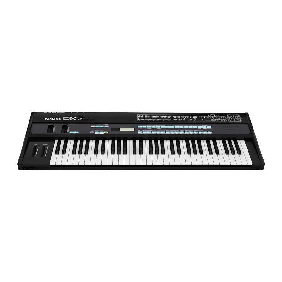
Yamaha DX7 Service Manual
Digital programmable algorithm synthesizer
Hide thumbs
Also See for DX7:
- Manual (85 pages) ,
- Operation manual (72 pages) ,
- Instruction manual (43 pages)
Table of Contents
Advertisement
Advertisement
Table of Contents

Summary of Contents for Yamaha DX7
- Page 7 DX7 CIRCUIT DESCRIPTION Keyboard and Panel Switch Scanning The 4 bits BO ~ B3 from the sub-CPU (6805S) are input to the decoder (40H138). The decoder output is sent to the keyboard transfer contacts and the panel switches. The on or off state of the keyboard break contacts, make contacts and panel switches are sent to the sub-CPU AO ~ A7 lines via a line driver (40H240) when the sub-CPU B4 and B5 lines are low.
- Page 8 4-6. Data is not accepted from the panel switches and keys while the sub-CPU C2 line is low. Main CPU Operation The main CPU mode is set by externally initializing lines P20~P22. When “L, L, H” is applied to the P20~P22 lines and latched into the CPU on the rising edge of RES, the Extended Multiplex Mode is selected.
- Page 9 Data from the main CPU is decoded and displayed at the LCD unit. EGS (Envelope Generator) 8 bits of data are received from the main CPU, and envelope and frequency data are sent to OPS. OPS (Operator) The OPS uses a sine table to generate waveform data to be sent to the DAC from the received envelope and frequency data.
- Page 11 it takes until Ll is reached from L4. The larger the Rl value, the sharper the attack. Rates and levels determine the basic shape of the envelope, but the actual envelope shape is affected by output level and key scaling. Output Level Buffer Output level buffer receives data concerning key scaling, after touch, and output level from the CPU.
- Page 12 Frequency Buffer Frequency data related to key code, pitch envelope, and transposition is received from the CPU and stored in the frequency buffer. Rate Scaling Buffer Data used to determine rate values according to key scaling is stored in the rate scaling buffer.


Need help?
Do you have a question about the DX7 and is the answer not in the manual?
Questions and answers