Table of Contents
Advertisement
Quick Links
Advertisement
Table of Contents

Subscribe to Our Youtube Channel
Related Manuals for Seagate DDS-4


Summary of Contents for Seagate DDS-4
- Page 1 Online Online User’s Guide User’s Guide DDS-4/DAT 72 DDS-4/DAT 72...
-
Page 2: Copyright And Trademarks
Part Number 10010539-001 May 2003 Certance and the Certance logo are trademarks of Certance LLC. Seagate is a trademark of Seagate Technol- ogy LLC. Other product names are trademarks or registered trademarks of their respective owners. Certance reserves the right to change, without notice, product offerings or specifications. No part of this publi- cation may be reproduced in any form without written permission from Certance LLC. -
Page 3: Fcc Notice
U.S. Government Printing Office, Washington, DC 20402. WARNING: Changes or modifications made to this equipment, which have not been expressly approved by Certance, may cause radio and television interference problems that could void the user's authority to operate the equipment. -
Page 5: Table Of Contents
Contents List of Figures ..............9 List of Tables..............10 Chapter 1 - Introduction ........... 11 ................12 Features ............ 13 Capacity and Transfer Rates ................. 13 Applications ..............13 Using This Guide Chapter 2 - Quick Start Installation ........ 14 ............ - Page 6 ..............22 Terminator Power ..............23 Data Compression ........23 Media Recognition System (DDS-4 Drives Only) ..............24 Power-On Self-Test ............24 Host Operating System ......25 SCSI Wide/Narrow Configuration (DDS-4 Drives Only) ................25 Vendor ID ............. 25 Recording Drive Information ........
- Page 7 ............38 Connecting a Power Cable ............. 39 Completing Your Installation ............. 39 Registering Your Tape Drive Chapter 5 - Operating Your Tape Drive ......40 ........... 40 Using the Appropriate Media .............. 41 Handling Cartridges ............... 42 Loading a Cartridge ...........
- Page 8 Appendix A - Loading Revised Firmware....... 53 ............ 53 Firmware Upgrade Methods ............54 Using Firmware Cartridges Appendix B - Technical Support Information....55 .............. 55 World-wide Services ..............55 World-wide Web ............55 E-mail Technical Support ..............56 Regional Services ............
-
Page 9: List Of Figures
List of Figures FIGURE 1. Drives Covered in This User’s Guide ..........11 FIGURE 2. Front Panel Components ..............14 FIGURE 3. Internal Tape Drive Jumper Settings ............ 20 FIGURE 4. Internal Tape Drive Switch Settings ............. 21 FIGURE 5. Mounting an Internal Tape Drive ............27 FIGURE 6. -
Page 10: List Of Tables
List of Tables TABLE 1. DDS-4 and DAT 72 Capacity and Transfer Rates ........13 TABLE 2. Internal Tape Drive Default Settings ............20 TABLE 3. SCSI IDs and Corresponding Jumper Settings ......... 21 TABLE 4. Host Operating Systems and Corresponding Switch Settings ....24 TABLE 5. -
Page 11: Chapter 1 - Introduction
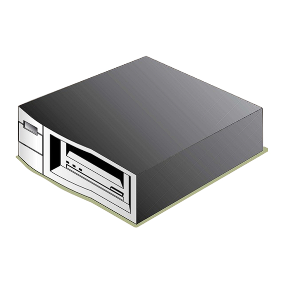
Designed for computer environments that require high-performance, high-capacity data storage, the DDS-4 and DAT 72 drives are based on a 3.5-inch mechanism and available as external and inter- nal tape drives (see Figure 1 on page 11). The drives combine established Digital Audio Tape (DAT) technology, high-density recording, and hardware data-compression capabilities with Certance’s... -
Page 12: Features
Introduction Features Features The following list summarizes the key features of the DDS-4 and DAT 72 drives. Compatibility • DDS-4: Supports DDS-2, DDS-3, and DDS-4 recording formats. • DAT 72: Supports DDS-3, DDS-4, and DDS 5 Generation recording formats. •... -
Page 13: Capacity And Transfer Rates
• Using This Guide This User’s Guide describes how to install, configure, and care for the DDS-4 and DAT 72 external and internal tape drives. Please read the appropriate chapters and appendixes carefully, and keep this Guide handy for future reference. -
Page 14: Chapter 2 - Quick Start Installation
Quick Start Installation This chapter provides quick-start instructions for getting the internal or external tape drives up and running in the shortest possible time. Topics in this chapter are: “Tape Drive Components” on page 14 • “Installing the Internal Tape Drive” on page 15 •... -
Page 15: Installing The Internal Tape Drive
• Media Recognition (DDS-4 drives only): Enabled • Power-On Self-Test: Enabled • Host Operating System: Windows 98/Me/XP/NT/2000/2003 Server • SCSI Interface Compatibility (DDS-4 drives only): Wide SCSI • Vendor ID: SEAGATE DAT See“Reviewing Drive Default Settings” on page 19. ❑... -
Page 16: Installing The External Tape Drive
• Media Recognition (DDS-4 drives only): Enabled • Power-On Self-Test: Enabled • Host Operating System: Windows 98/Me/XP/NT/2000/2003 Server • SCSI Interface Compatibility (DDS-4 drives only): Wide SCSI • Vendor ID: SEAGATE DAT See“Reviewing Drive Default Settings” on page 34. ❑... -
Page 17: Chapter 3 - Installing Internal Tape Drives
Installing internal tape drives This chapter describes how to install internal DDS-4 and DAT 72 drives. Topics in this chapter are: “Unpacking” on page 17 • “What Else You Need” on page 18 • “Avoiding Electrostatic Damage” on page 18 •... -
Page 18: What Else You Need
• Backup application software that supports the internal tape drive. For a list of the latest • backup software applications tested with the internal DDS-4 and DAT 72 tape drives, please visit our Web site at http://support.certance.com. Avoiding Electrostatic Damage Your internal tape drive has very sensitive components that are prone to damage from electrostatic discharge (ESD). -
Page 19: Collecting The Necessary Tools
Installing internal tape drives Collecting the Necessary Tools Access the Inside of the Computer See “Accessing the Inside of Your Computer” on page 26. Mount the Drive into the Computer Mounting Bay See “Mounting the Internal Tape Drive” on page 26. Attach a SCSI Interface Cable See “Connecting a SCSI Cable”... -
Page 20: Figure 3. Internal Tape Drive Jumper Settings
Data compression Enabled Switches 1 and 2 page 23 Media Recognition System checking Enabled Switch 3 page 23 (DDS-4 drives only) Power-On Self-Test diagnostic Enabled Switch 4 page 24 Host operating system Microsoft Windows Switches 5 through 8 page 24... -
Page 21: Scsi Id
Installing internal tape drives Reviewing Drive Default Settings Data compression (DC) SCSI DC control Media recognition Self Test Operating-system configuration switches Wide/Narrow SCSI Inquiry String support Default settings shown Front of drive Internal Tape Drive Switch Settings FIGURE 4. SCSI ID Jumper Pins: 1–2, 3–4, 5–6, 7–8 Default Setting: SCSI ID 6... -
Page 22: Parity Checking
Installing internal tape drives Reviewing Drive Default Settings TABLE 3. SCSI IDs and Corresponding Jumper Settings (Continued) Jumpers SCSI ID 1–2 3–4 5–6 7–8 Open Open Shunted Shunted Shunted Open Shunted Shunted Open Shunted Shunted Shunted Shunted Shunted Shunted Shunted NOTES: You can also change SCSI IDs by connecting a SCSI address-selection switch to pins 1 through 8. -
Page 23: Data Compression
2:1 or more. Data with little redundancy, such as executable programs, are compressed the least. • Media Recognition System (DDS-4 Drives Only) Settings: Switch 3 ON = Enable MRS (default) Switch 3 OFF = Disable MRS Using non-DDS media may appear to give satisfactory results, but the inferior specifications of such media can cause data-integrity problems. -
Page 24: Power-On Self-Test
Refer to the operating system drive configuration supplement for information on scripts and • other settings for various non-Windows operating systems. This supplement is available on your Tape Resource CD and at http://support.certance.com. Table 4 shows the supported operating systems and their corresponding switch settings. TABLE 4. -
Page 25: Scsi Wide/Narrow Configuration (Dds-4 Drives Only)
Switch 9 enables SCSI Wide or Narrow operation. By default, switch 9 is set to ON, enabling SCSI Wide (16-bit) operation. To enable SCSI Narrow (8-bit) operation, set switch 9 to the OFF position. This allows the DDS-4 drive to terminate the upper byte of the SCSI bus. NOTE: Narrow SCSI is not recommended. -
Page 26: Accessing The Inside Of Your Computer
Installing internal tape drives Accessing the Inside of Your Computer Accessing the Inside of Your Computer To gain access to the inside of your computer: Shut down the computer as you would normally. Then turn off the computer and all peripherals connected to it. -
Page 27: Figure 5. Mounting An Internal Tape Drive
Installing internal tape drives Mounting the Internal Tape Drive Secure the drive in the mounting bay using two M3.0 metric screws on each side of the drive (see Figure 5 on page 27). As Figure 6 on page 27 shows, the 3.5-inch drive has four screw holes on the bottom and five on each side. -
Page 28: Mounting The Drive Into A 5.25-Inch Drive Bay
Installing internal tape drives Mounting the Internal Tape Drive Mounting the Drive into a 5.25-inch Drive Bay The following procedure describes how to mount the drive in a 5.25-inch drive bay. This procedure assumes your drive has mounting brackets on the sides. Orient the drive so the front of the drive faces the front of the computer. -
Page 29: Connecting A Scsi Cable
Installing internal tape drives Connecting a SCSI Cable Connecting a SCSI Cable The internal tape drives can be used with two SCSI interfaces: • Wide SCSI — either Low Voltage Differential (LVD) or Single-ended (16-bit Wide mode), • Narrow SCSI — either Low Voltage Differential (LVD) or Single-ended (8-bit Wide mode). The tape drive automatically detects whether the SCSI bus is LVD or single ended. -
Page 30: Checking Scsi Termination
Installing internal tape drives Checking SCSI Termination Checking SCSI Termination The internal tape drives do not provide SCSI termination. For this reason, they should not be the last device on a SCSI chain. Figure 9 on page 30 shows two examples of terminating the internal tape drives. -
Page 31: Completing Your Installation
Installing internal tape drives Completing Your Installation Power Connector on the Internal Tape Drive FIGURE 10. Completing Your Installation To complete and test your internal tape drive installation: Use the screws you removed earlier to secure the drive in place. Replace the computer cover. -
Page 32: Registering Your Tape Drive
For your convenience, you can register your drive either through our Web site or by fax. If you have an Internet connection, please visit www.certance.com and select “Product • Registration” from the “Products” menu. -
Page 33: Chapter 4 - Installing External Tape Drives
Installing external tape drives This chapter describes how to install external DDS-4 and DAT 72 drives. Topics in this chapter are: “Unpacking” on page 33 • “What Else You Need” on page 33 • “Installation Summary” on page 34 •... -
Page 34: Installation Summary
Installation Summary Backup application software that supports the external tape drive. For a list of the latest • backup software applications tested with the external DDS-4 and DAT 72 tape drives, please visit our Web site at http://support.certance.com. Installation Summary The following steps summarize the installation procedure for your external tape drive. -
Page 35: Scsi Id
Installing external tape drives Reviewing Drive Default Settings TABLE 5. External Tape Drive Default Settings (Continued) Parameter Default Setting See... Media Recognition System checking (DDS-4 drives only) Enabled page 36 Power-On Self-Test diagnostic Enabled page 36 Host operating system Microsoft Windows 98/Me/... -
Page 36: Media Recognition System (Dds-4 Drives Only)
Data with little redundancy, such as executable programs, are compressed the least. • Media Recognition System (DDS-4 Drives Only) Using non-DDS media may appear to give satisfactory results, but the inferior specifications of such media can cause data-integrity problems. To avoid these problems, the external tape drive provides a media-recognition system (MRS) feature that determines whether tape cartridges conform to the DDS tape standard. -
Page 37: Connecting A Scsi Cable
Installing external tape drives Connecting a SCSI Cable Connecting a SCSI Cable The external tape drives provide two 68-pin, shielded connectors on the back panel (see Figure 11 on page 35). You can use either connector to attach the drive to the host computer or to another SCSI device. -
Page 38: Checking Scsi Termination
Installing external tape drives Checking SCSI Termination NOTE: Be sure the upper 8 data bytes of the 68-pin cable are properly terminated. Checking SCSI Termination If the external tape drive is the last or only device in the SCSI chain, install a terminating plug on the unused SCSI connector on the drive’s back panel. -
Page 39: Completing Your Installation
For your convenience, you can register your drive either through our Web site or by fax. If you have an Internet connection, please visit www.certance.com and select “Product • Registration” from the “Products” menu. -
Page 40: Chapter 5 - Operating Your Tape Drive
“Cleaning the Tape Heads” on page 45 • Using the Appropriate Media The Seagate DDS-4 and DAT 72 drives use data-grade DDS cartridges, which comply with ANSI specifications listed in the “3.81 mm Helical-Scan Digital Computer Tape Cartridge for Information Interchange,” ANSI X3B5/89-156 standard. -
Page 41: Handling Cartridges
Operating Your Tape Drive Handling Cartridges TABLE 6. Matching Drives with the Media They Support Media Tape Length DDS-4 Drives DAT 72 Drives DDS-2 120 meters DDS-3 125 meters DDS-4 150 meters 170 meters DDS 5 Generation Handling Cartridges To protect your data cartridges and the information on them, observe the guidelines and avoid the pitfalls in Table 7 on page 41. -
Page 42: Loading A Cartridge
Operating Your Tape Drive Loading a Cartridge Loading a Cartridge Seagate DDS drives have a front-loading cartridge bay for easy operation. To load a cartridge: Hold the cartridge so the label is facing up and the exposed media is facing the drive. Gently insert the cartridge into the drive (see Figure 13 on page 42). -
Page 43: Unloading A Cartridge
Operating Your Tape Drive Unloading a Cartridge Unloading a Cartridge To unload a cartridge: Be sure the Drive LED is OFF. CAUTION: To ensure integrity of your backups and restores, do not press the Eject button when the Drive LED is ON. Press the Eject button on the front panel of the drive to unload the cartridge (see Figure 14 on page 43). -
Page 44: Write-Protecting A Dds Cartridge
Operating Your Tape Drive Write-Protecting a DDS Cartridge Write-Protecting a DDS Cartridge Write-protecting a DDS cartridge protects the data on the cartridge from being changed, overwrit- ten, or deleted. To write-protect a cartridge, slide the write-protect tab on the back of the cartridge to the open position (see Figure 15 on page 44). -
Page 45: Cleaning The Tape Heads
30 cleaning cycles, the entire tape is used up and should be replaced. The Clean LED flashes when the cleaning cartridge needs to be replaced. The DDS-4 and DAT 72 drives have a TapeAlert feature that notifies your backup software •... -
Page 46: Chapter 6 - Understanding The Drive Leds
Front Panel LEDs Figure 16 on page 46 shows an example of the LEDs on the drive front panel of the DDS-4 and DAT 72 drives. The external tape drive has the same front-panel LEDs, plus a green Power-On LED. -
Page 47: Led Summary
Understanding the Drive LEDs LED Summary LED Summary Table 8 on page 47 summarizes the actions of the front-panel LEDs. TABLE 8. LED Quick Summary Color Action Description Clean Green ON (Lit) Cleaning is required. Slow Flashing Internal error rate threshold has been exceeded and cleaning is required. -
Page 48: Media Led
Understanding the Drive LEDs Media LED Media LED The Media LED indicates whether a DDS cartridge is operating normally. TABLE 10. Media LED LED Status Description ON continuously A DDS cartridge has been inserted and the drive is operating normally. Flashing rapidly Drive could not write the tape correctly (maximum rewrite count exceeded) and the write operation failed. -
Page 49: Chapter 7 - Troubleshooting
• “Write Error” on page 52 • “Hardware Error” on page 52 • Missing or Damaged Parts If any of the contents included with your DDS-4 or DAT 72 drive are missing or damaged, contact your place of purchase immediately. -
Page 50: Scsi Id Problems
SCSI Termination Problems If an external DDS-4 or DAT 72 drive is the last device or the only device in a SCSI chain, you must install a terminating plug on the unused SCSI connector. For more information, see “Checking SCSI Termination”... -
Page 51: Power-On Self-Test Fails
SCSI ID to the drive or to the conflicting device. Check that the SCSI bus is terminated properly. Note that the internal DDS-4 and DAT 72 drives do not provide SCSI termination and, therefore, should not be the last devices on a... -
Page 52: Backup Program Does Not Recognize Drive
Troubleshooting Backup Program Does Not Recognize Drive Backup Program Does Not Recognize Drive If your backup application program does not recognize the drive: Use the Windows Device Manager to determine whether the operating system has recognized the drive. If the tape drive is recognized properly, it appears under the Tape Drive category. If the tape drive was recognized, but native drivers are not installed, it appears under Other Devices. -
Page 53: Appendix A - Loading Revised Firmware
Your DDS-4 or DAT 72 tape drive includes permanently installed, electrically upgradeable flash memory. This memory allows qualified OEMs to revise DAT 72 and DDS-4 SCSI firmware quickly and easily. It also prolongs the life of the tape drive by allowing the drive to inherit leading technol- ogies as soon as those technologies become available. -
Page 54: Using Firmware Cartridges
NOTE: The firmware can also be upgraded from a host computer via the SCSI connection using software available at http://support.certance.com. Power on the host system with the DDS-4 or DAT 72 drive installed. Close all applications that might try to communicate with the drive during the firmware upgrade procedure. -
Page 55: Appendix B - Technical Support Information
“Support Services in Asia and the Western Pacific” on page 58 • World-wide Services World-wide Web A wide variety of technical support services are available on the World Wide Web site, located at http://support.certance.com E-mail Technical Support You can e-mail questions or comments to: tapesupport@certance.com. -
Page 56: Regional Services
Technical Support Information Regional Services Regional Services We provide technical support through several regional centers worldwide. These services may include the following. Phone Technical Support For one-on-one help, you can talk to a technical-support specialist during local business hours. Before calling, note your system configuration and drive model number. If you recorded this informa- tion as suggested, have it handy. -
Page 57: Support Services In Europe
Technical Support Information Support Services in Europe Support Services in Europe For European customer support and SeaFAX, dial the toll-free number for your specific country from Table 12 on page 57. The Seagate Technical Support FAX number for all European countries is: 31-20-653-3513. -
Page 58: Support Services In Asia And The Western Pacific
Technical Support Information Support Services in Asia and the Western Pacific Support Services in Asia and the Western Pacific Various technical support services are available from different regional centers, as shown in Table 13 on page 58. SeaFAX is available in Australia at 61-2-9756-5170. TABLE 13. - Page 59 Cables external drives 35 Power (external drives) 38 internal drives 23 Power (internal drives) 30 DDS cartridge, write-protecting 44 SCSI (internal drives) 29 DDS-4 applications 13 Capacity 13 capacity and transfer rates 13 Cartridges 41 features 12 appropriate 40 LEDs 46...
- Page 60 E-mail technical support 55 connecting to a wide SCSI connector 29 European technical support 57 data compression 23 External drives default settings 19 connecting a power cable 38 host operating system 24 connecting a SCSI cable 37 installation summary 18 data compression 35 installing 17 default settings 34...
- Page 61 problems 50 Operation SCSI Wide/Narrow configuration cartridge guidelines 41 internal drives 25 cleaning tape heads 45 Switch settings for internal drives 21 handling cartridges 41 initializing a blank cartridge 42 Tape cartridges loading a cartridge 42 appropriate 40 unloading a cartridge 43 handling 41 using appropriate media 40 initializing 42...
- Page 62 hardware error 52 missing or damaged parts 49 mounting hardware problems 50 Power-On Self-Test fails 51 SCSI ID problems 50 SCSI termination problems 50 write error 52 Unloading a cartridge 43 Unpacking external drives 33 internal drives 17 Upgrading firmware 53 Vendor ID internal drives 25 Write error 52...
Need help?
Do you have a question about the DDS-4 and is the answer not in the manual?
Questions and answers