Table of Contents
Advertisement
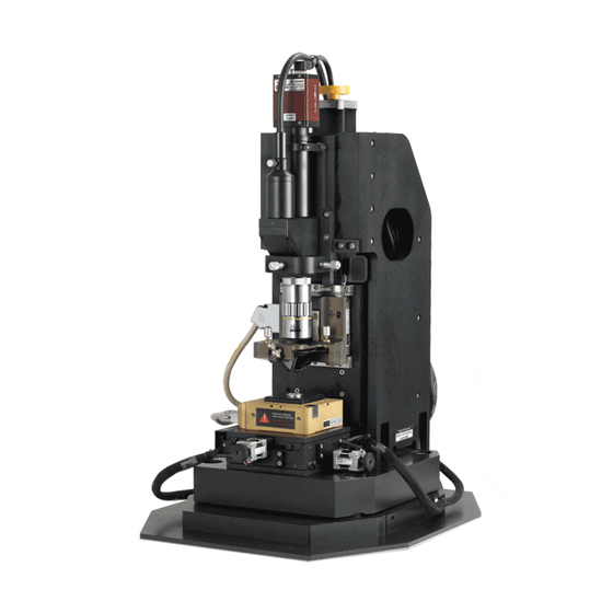
Park XE-100 AFM User Manual
Ed Fei and Ryan Brock
Updated 10/30/13
NOTE: This document is intended as a quick reference for basic operation of the
Park XE-100 and is by no means a comprehensive manual. It is strongly suggested
that users look through the Park documentation. The better you understand the
instrument, the more effectively you will be able to use it.
This device is highly
similar to the Park XE-70. Differences have been highlighted in green.
Basic AFM Principles
When the tip is suspended in air, the laser will hit the center of the quadrant photodetector.
If the tip encounters a feature on the surface, the tip deflects and the laser will move on the
quadrant photodetector. This is relayed to a motor controlling the tip which adjusts the tip's
vertical position until the laser is aimed in the center of the quadrant photodetector once again.
Effectively, this keeps the tip at a constant distance from the sample surface. By recording the
position of the motor height, we can now know the topography of the sample surface.
The tips provided in this lab are intended for 'non-contact' AFM, which is similar in principle to
what is described above. Rather than relying on physical contact with the surface, the
cantilever/tip is oscillated at a given frequency above the sample surface, and interactive forces
from the surface lead to changes in the amplitude/phase of this oscillation.
Setting up the AFM is simple: adjust the mirrors until the light path follows the diagram below
Advertisement
Table of Contents

Related Manuals for Park Systems XE-100


Summary of Contents for Park Systems XE-100
- Page 1 NOTE: This document is intended as a quick reference for basic operation of the Park XE-100 and is by no means a comprehensive manual. It is strongly suggested that users look through the Park documentation. The better you understand the instrument, the more effectively you will be able to use it.
- Page 2 Login To Badger, Enable Device Hardware Setup 1) Unplug head and remove it by pulling flaps towards you and sliding head out to the right. Never handle head from bottom to ensure safety of the AFM tip. 2) Mount sample on stage 3) Mount a new tip if one is not already mounted.
- Page 3 Aim Laser on End of Cantilever (Adjust Mirror 1) Open ‘XEP’ program, press OK if frequency sweep window opens. On the XE-100, the optical microscope position (‘Focus Stage’) is controlled through the software similarly to how the Z-stage position is controlled. When ‘Focus Follow’ is selected, the Focus Stage will match any movements made by the Z-stage –...
- Page 4 Aim Laser on Center of Photodetector (Adjust Mirror 2) XEP software should already be open. 2) Check (A+B) voltage value (measures total intensity of light hitting the photodetector), which should be ~3-3.5 V if using ACTA tips provided by the lab. - The correct value will be different if you use your own tips.
- Page 5 Mode, Scanner, and Frequency Selection 1) Turn off Head in software 2) Click on Parts Select 3) Select proper mode of operation and scanner ranges Head Mode: NC-AFM - ACTA tips should only be used for NC-AFM (non-contact mode) XY Voltage Mode: High (50um x 50um) or Low (5umx5um) Z Voltage Mode: High (12 um) or Low (1.7 um) Z Scanner Range: Set to 1.00 Cantilever: General...
- Page 6 Initial Surface Approach 1) Ensure sample is under the tip by adjusting the x/y stage controls. 2) Using Z-stage control window (with Focus Follow enabled), approach surface to within a few mm. Only go as far as you feel comfortable that the tip is still well away from surface. 3) Using Focus Stage control window, focus on sample.
- Page 7 Optimize Scan Parameters 1) Click on Input configuration icon 2) Select channels of interest, show at least trace and retrace of topography 3) Change the scan size to appropriate value (5µm or 50µm max depending on XY scanner) A good image is achieved when trace and retrace show the same topography and are stable (repeatedly show the same topography and there are no random spikes or other instabilities).
- Page 8 Collect Image 1) Click on Scan Parameters icon to select image resolution (128x128, 256x256, etc). 1a) You may need to adjust the scan parameters slightly after making a change. 2) Click Start button under Image label. 3) Once complete, double click on the color bars next to the images. This will flatten the image. You can send the image to the Scan Area Control by right clicking on the image, and hit “Send to Scan Area Control”.
- Page 9 Shut down CAUTION: ENSURE HEAD WILL NOT CONTACT MICROSCOPE!! DO NOT “Lift Z” right away. The stage will hit the microscope on the way up and damage one or both of them. Use Z-stage control to lift tip away from sample a small distance so the tip is no longer touching the sample.
- Page 10 XE-100 AFM Order of Operations 1) Turn on system, mount tip if needed 2) Turn on XEC/XEP software 3) Focus microscope on cantilever 4) Position laser spot on end of cantilever 5) Position laser reflection on center of photodetector (A+B ~3.5V, A-B and C-D ~0.3V)
Need help?
Do you have a question about the XE-100 and is the answer not in the manual?
Questions and answers