Table of Contents
Advertisement
Advertisement
Table of Contents

Related Manuals for MSI Z87M GAMING


Summary of Contents for MSI Z87M GAMING
- Page 1 Preface Z87M GAMING Motherboard G52-78661X1...
-
Page 2: Preface
Copyright Notice The material in this document is the intellectual property of MICRO-STAR INTERNATIONAL. We take every care in the preparation of this document, but no guarantee is given as to the correctness of its contents. Our products are under continual improvement and we reserve the right to make changes without notice. -
Page 3: Smartphone Application
If a problem arises with your system and no solution can be obtained from the user’s manual, please contact your place of purchase or local distributor. Alternatively, please try the following help resources for further guidance. Visit the MSI website for technical guide, BIOS updates, driver updates, and other information: http://www.msi.com/service/download/ Contact our technical staff at: http://support.msi.com... -
Page 4: Safety Instructions
Safety Instructions ■ Always read the safety instructions carefully. ■ Keep this User’s Manual for future reference. ■ Keep this equipment away from humidity. ■ Lay this equipment on a reliable flat surface before setting it up. ■ The openings on the enclosure are for air convection hence protects the equipment from overheating. -
Page 5: Fcc-B Radio Frequency Interference Statement
FCC-B Radio Frequency Interference Statement This equipment has been tested and found to comply with the limits for a Class B digital device, pursuant to Part 15 of the FCC Rules. These limits are designed to provide reasonable protection against harmful interference in a residential installation. This equipment generates, uses and can radiate radio frequency energy and, if not installed and used in accordance with the instructions, may cause harmful interference to radio communications. -
Page 6: Radiation Exposure Statement
Radiation Exposure Statement This equipment complies with FCC radiation exposure limits set forth for an uncontrolled environment. This equipment and its antenna should be installed and operated with minimum distance 20 cm between the radiator and your body. This equipment and its antenna must not be co-located or operating in conjunction with any other antenna or transmitter. -
Page 7: Battery Information
Replace only with the same or equivalent type recommended by the manufacturer. Chemical Substances Information In compliance with chemical substances regulations, such as the EU REACH Regulation (Regulation EC No. 1907/2006 of the European Parliament and the Council), MSI provides the information of chemical substances in products at: http://www.msi.com/html/popup/csr/evmtprtt_pcm.html Preface... -
Page 8: Weee (Waste Electrical And Electronic Equipment) Statement
MSI will comply with the product take back requirements at the end of life of MSI-branded products that are sold into the EU. You can return these products to local collection points. - Page 9 MSI će poštovati zahtev o preuzimanju ovakvih proizvoda kojima je istekao vek trajanja, koji imaju MSI oznaku i koji su prodati u EU. Ove proizvode možete vratiti na lokalnim mestima za prikupljanje.
- Page 10 MSI si adeguerà a tale Direttiva ritirando tutti i prodotti marchiati MSI che sono stati venduti all’interno dell’Unione Europea alla fine del loro ciclo di vita.
-
Page 11: Table Of Contents
CONTENTS ▍ Preface ......................i Copyright Notice ......................ii Trademarks ......................ii Revision History ......................ii Smartphone Application ..................iii Technical Support ....................iii Safety Instructions ....................iv FCC-B Radio Frequency Interference Statement ........... v CE Conformity ......................v Radiation Exposure Statement ................vi European Community Compliance Statement ............vi Taiwan Wireless Statements ...................vi Japan VCCI Class B Statement ................vi Korea Warning Statements ..................vi... - Page 12 Internal Connectors .................... 1-24 SATA1~6: SATA Connectors ..............1-24 CPUFAN1~2,SYSFAN1~2: Fan Power Connectors ........1-25 JFP1, JFP2: System Panel Connectors ............1-26 JUSB1~2: USB 2.0 Expansion Connector ........... 1-27 JUSB3: USB 3.0 Expansion Connector ............1-27 JTPM1: TPM Module Connector ..............1-28 JCI1: Chassis Intrusion Connector ..............
- Page 13 Overview ......................3-3 Operation ......................3-5 SETTINGS ......................3-6 System Status ....................3-6 Advanced ....................... 3-7 Boot ......................3-13 Security ......................3-13 Save & Exit ....................3-14 OC ........................3-15 M-FLASH ......................3-25 OC PROFILE ..................... 3-26 HARDWARE MONITOR ..................3-27 Appendix A Realtek Audio ................
-
Page 15: Chapter 1 Getting Started
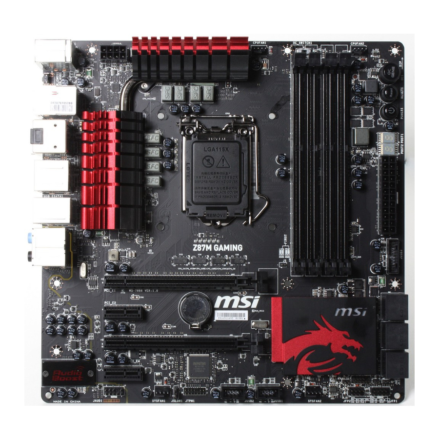
Chapter 1 Getting Started Thank you for choosing the Z87M GAMING Series (MS-7866 v1.X) Mirco-ATX motherboard. The Z87M GAMING Series motherboards are based on Intel Z87 chipset for optimal system efficiency. Designed to ® fit the advanced Intel LGA1150 processor, the Z87M GAMING Series ®... -
Page 16: Packing Contents
* These pictures are for reference only and may vary without notice. * The packing contents may vary according to the model you purchased. * If you need to purchase the optional accessories or request part numbers, please visit the MSI website at http://www.msi.com/index.php or consult the dealer. Getting Started... -
Page 17: Assembly Precautions
Assembly Precautions ■ The components included in this package are prone to damage from electrostatic discharge (ESD). Please adhere to the following instructions to ensure successful computer assembly. ■ Always turn off the power supply and unplug the power cord from the power outlet before installing or removing any computer component. -
Page 18: Motherboard Specifications
Motherboard Specifications ■ 4th Generation Intel Core™ i7 / Core™ i5 / Core™ i3 / Pentium ® ® Celeron processors for LGA 1150 socket Support ® Chipset ■ Intel Z87 Express Chipset ® Memory ■ 4x DDR3 memory slots supporting up to 32GB ■... - Page 19 ■ 1x Killer E2205 Gigabit LAN controller* * The Killer Network Manager is only available for Windows 7 and Windows 8 currently. The supported drivers for other operating systems would be available on the website if provided by vendor. Back Panel ■...
- Page 20 Killer Network Manager Form ■ Micro-ATX Form Factor ■ 9.6 in. x 9.6 in. (24.4 cm x 24.4 cm) Factor For the latest information about CPU, please visit http://www.msi.com/service/cpu-support/ For more information on compatible components, please visit http://www.msi.com/service/test-report/ Getting Started...
-
Page 21: Connectors Quick Guide
Connectors Quick Guide DIMM3 DIMM2 DIMM4 OC_SWITCH1 CPUFAN2 DIMM1 JPWR2 CPUFAN1 CPU Socket RESET1 POWER1 Back Panel JPWR1 JUSB3 PCI_E1 SATA1_2 PCI_E2 SATA3_4 PCI_E3 SATA5_6 PCI_E4 JCI1 SYSFAN1 JFP1 JSLOW1 JFP2 JAUD1 JBAT1 JTPM1 JUSB2 SYSFAN2 JUSB1 Getting Started... - Page 22 Connectors Reference Guide Port Name Port Type Page Back Panel CPU Socket LGA1150 CPU Socket 1-12 CPUFAN1~2,SYSFAN1~2 Fan Power Connectors 1-25 DIMM1~4 DDR3 Memory Slots 1-15 JAUD1 Front Panel Audio Connector 1-29 JBAT1 Clear CMOS Jumper 1-32 JCI1 Chassis Intrusion Connector 1-28 JFP1, JFP2 System Panel Connectors...
-
Page 23: Back Panel Quick Guide
Back Panel Quick Guide Optical PS/2 Keyboard/ S/PDIF-Out Mouse Combo USB 3.0 Port Port USB 3.0 Port LAN Port Line-In RS-Out HDMI Line-Out CS-Out SS-Out USB 2.0 Port USB 3.0 Port DisplayPort HDMI eSATA Port Clear CMOS Button ▶ PS/2 Keyboard/ Mouse Combo Port A combination of PS/2 mouse/keyboard DIN connector for a PS/2 mouse/keyboard. - Page 24 ® ▶ HDMI Port The High-Definition Multimedia Interface (HDMI) is an all-digital audio-video interface that is capable of transmitting uncompressed streams. HDMI supports all types of TV formats, including standard, enhanced, or high-definition video, plus multi-channel digital audio on a single cable. ▶...
-
Page 25: Cpu (Central Processing Unit)
This motherboard is designed to support overclocking. Before attempting to overclock, please make sure that all other system components can tolerate overclocking. Any attempt to operate beyond product specifications is not recommend. MSI does not guarantee the damages or risks caused by inadequate operation beyond product specifications. -
Page 26: Cpu & Heatsink Installation
CPU & Heatsink Installation When installing a CPU, always remember to install a CPU heatsink. A CPU heatsink is necessary to prevent overheating and maintain system stability. Follow the steps below to ensure correct CPU and heatsink installation. Wrong installation can damage both the CPU and the motherboard. - Page 27 3. Align the notches with the socket alignment keys. Lower the CPU straight down, without tilting or sliding the CPU in the socket. Inspect the CPU to check if it is properly seated in the socket. 4. Close and slide the load plate under the retention knob. Close and engage the load lever.
- Page 28 7. Locate the CPU fan connector on the motherboard. 8. Place the heatsink on the motherboard with the fan’s cable facing towards the fan connector and the fasteners matching the holes on the motherboard. CPU fan connector 9. Push down the heatsink until the four fasteners get wedged into the holes on the motherboard.
-
Page 29: Memory
Memory These DIMM slots are used for installing memory modules. For more information on compatible components, please visit http://www.msi.com/service/test-report/ DIMM1 DIMM2 DIMM3 DIMM4 Video Demonstration Watch the video to learn how to install memories at the address below. http://youtu.be/76yLtJaKlCQ Dual-Channel mode Population Rule In Dual-Channel mode, the memory modules can transmit and receive data with two data bus channels simultaneously. -
Page 30: Mounting Screw Holes
Mounting Screw Holes When installing the motherboard, first install the necessary mounting stands required for an motherboard on the mounting plate in your computer case. If there is an I/O back plate that came with the computer case, please replace it with the I/O backplate that came with the motherboard package. -
Page 31: Power Supply
Power Supply Video Demonstration Watch the video to learn how to install power supply connectors. http://youtu.be/gkDYyR_83I4 JPWR1~2: ATX Power Connectors These connectors allow you to connect an ATX power supply. To connect the ATX power supply, align the power supply cable with the connector and firmly press the cable into the connector. -
Page 32: Expansion Slots
Expansion Slots This motherboard contains numerous slots for expansion cards, such as discrete graphics or audio cards. PCI_E1~E4: PCIe Expansion Slots The PCIe slot supports the PCIe interface expansion card. PCIe 3.0 x16 Slot PCIe 2.0 x1 Slot Important When adding or removing expansion cards, always turn off the power supply and unplug the power supply power cable from the power outlet. -
Page 33: Video/ Graphics Cards
Adding on one or more discrete video cards will significantly boost the system’s graphics performance. For best compatibility, MSI graphics cards are recommended. Video Demonstration Watch the video to learn how to install a graphics card on PCIe x16 slot with butterfly lock. -
Page 34: Amd Crossfire™ (Multi-Gpu) Technology
Important Please ensure that all graphics cards used in CrossFire™ mode are of the same • brand and specifications. For best compatibility with the motherboard, MSI graphics cards are recommended. • Make sure to connect an adequate power supply to the power connectors on the graphics cards to ensure stable operation. - Page 35 Boot up the computer and install the drivers and software included in your video card package. For more information, please refer to the manual that came with your video card. After all of the hardware and software has been properly installed, reboot the system.
-
Page 36: Nvidia ® Sli Technology
NVIDIA SLI Technology ® NVIDIA’s SLI (Scalable Link Interface) technology allows two or more GPUs to run in tandem within a system to achieve significant graphics performance gains. To utilize this technology, the GPU cards must be connected by an SLI Video Link. If you intend to use SLI mode, please follow the instructions below to properly set up SLI mode. - Page 37 Important Please ensure that all graphics cards used in SLI mode are of the same brand and • specifications. For best compatibility with the motherboard, MSI graphics cards are recommended. • Make sure to connect an adequate power supply to the power connectors on the graphics cards to ensure stable operation.
-
Page 38: Internal Connectors
Internal Connectors SATA1~6: SATA Connectors This connector is a high-speed SATA interface port. Each connector can connect to one SATA device. SATA devices include disk drives (HDD), solid state drives (SSD), and optical drives (CD/ DVD/ Blu-Ray). Video Demonstration Watch the video to learn how to Install SATA HDD. http://youtu.be/RZsMpqxythc SATA2 SATA1... -
Page 39: Cpufan1~2,Sysfan1~2: Fan Power Connectors
CPUFAN1~2,SYSFAN1~2: Fan Power Connectors The fan power connectors support system cooling fans with +12V. If the motherboard has a System Hardware Monitor chipset on-board, you must use a specially designed fan with a speed sensor to take advantage of the CPU fan control. Remember to connect all system fans. -
Page 40: Jfp1, Jfp2: System Panel Connectors
JFP1, JFP2: System Panel Connectors These connectors connect to the front panel switches and LEDs. The JFP1 connector is compliant with the Intel Front Panel I/O Connectivity Design Guide. When ® installing the front panel connectors, please use the optional M-Connector to simplify installation. -
Page 41: Jusb1~2: Usb 2.0 Expansion Connector
JUSB1~2: USB 2.0 Expansion Connector This connector is designed for connecting high-speed USB peripherals such as USB HDDs, digital cameras, MP3 players, printers, modems, and many others. Important Note that the VCC and GND pins must be connected correctly to avoid possible damage. -
Page 42: Jtpm1: Tpm Module Connector
JTPM1: TPM Module Connector This connector connects to a optional TPM (Trusted Platform Module) Module. Please refer to the TPM security platform manual for more details and usages. JCI1: Chassis Intrusion Connector This connector connects to the chassis intrusion switch cable. If the computer case is opened, the chassis intrusion mechanism will be activated. -
Page 43: Jaud1: Front Panel Audio Connector
JAUD1: Front Panel Audio Connector This connector allows you to connect the front audio panel located on your computer case. This connector is compliant with the Intel Front Panel I/O Connectivity Design ® Guide. 1-29 Getting Started... -
Page 44: Buttons & Switches
BIOS section of the manual for instructions on how to turn off OC Genie from the BIOS. • The usage of OC Genie is at the user’s own risk. Overclocking is never guaranteed by MSI. • To ensure successfully OC Genie usage, MSI components are recommended. Getting Started 1-30... -
Page 45: Power1: Power Button
POWER1: Power Button This button is used to turn-on and turn-off the system. Press the button once to turn-on or turn-off the system. RESET1: Reset Button This reset button is used to reset the system. Press the button to reset the system. OC_SWITCH1: OC Genie Mode Switch This swtich provides two overclocking modes (Gear 1 and Gear 2) for OC Genie operation. -
Page 46: Jumpers
Jumpers JBAT1: Clear CMOS Jumper There is CMOS RAM onboard that is external powered from a battery located on the motherboard to save system configuration data. With the CMOS RAM, the system can automatically boot into the operating system (OS) every time it is turned on. If you want to clear the system configuration, set the jumpers to clear the CMOS RAM. -
Page 47: Jslow1: Slow Mode Booting Jumper
JSLOW1: Slow Mode Booting Jumper This jumper is used for LN2 cooling solution, that provides the extreme overclocking conditions, to boot at a stable processor frequency and to prevent the system from crashing. Normal Enabled (Default) Important Users will try extreme low temperature overclocking at their own risks. The overclocking results will vary according to the CPU version. -
Page 48: Led Status Indicators
LED Status Indicators 2-Digit Debug Code LED Getting Started 1-34... -
Page 49: Debug Code Led Table
Debug Code LED Table Please refer to the table below to get more information about the Debug Code LED message. Post Status 02,07 Power on CPU Initialization 03,08 Power on North Bridge Initialization 04,09 Power on South Bridge Initialization Power on Cache Initialization 11~14,32~36,56~5A Early CPU Initialization 15~18,37~3A... -
Page 50: Drivers And Utilities
After you install the operating system you will need to install drivers to maximize the performance of the new computer you just built. MSI motherboard comes with a Driver Disc. Drivers allow the computer to utilize your motherboard more efficiently and take advantage of any special features we provide. - Page 51 Chapter 2 Quick Installation This chapter provides demonstration diagrams about how to install your computer. Some of the installations also provide video demonstrations. Please link to the URL to watch it with the web browser on your phone or tablet. You may have even link to the URL by scanning the QR code. Important The diagrams in this chapter are for reference only and may vary from the product you purchased.
- Page 52 CPU Installation http://youtu.be/bf5La099urI Quick Installation...
-
Page 53: Chapter 2 Quick Installation
Quick Installation... -
Page 54: Memory Installation
Memory Installation http://youtu.be/76yLtJaKlCQ Quick Installation... -
Page 55: Motherboard Installation
Motherboard Installation Quick Installation... - Page 56 Quick Installation...
-
Page 57: Power Connectors Installation
Power Connectors Installation http://youtu.be/gkDYyR_83I4 Quick Installation... - Page 58 Quick Installation...
-
Page 59: Sata Hdd Installation
SATA HDD Installation http://youtu.be/RZsMpqxythc Quick Installation... -
Page 60: Msata Ssd Installation
mSATA SSD Installation Quick Installation 2-10... -
Page 61: Front Panel Connector Installation
Front Panel Connector Installation JFP1 Connecotr Installation http://youtu.be/DPELIdVNZUI Front Panel Audio Connector Installation 2-11 Quick Installation... -
Page 62: Peripheral Connector Installation
Peripheral Connector Installation USB2.0 Connector Installation USB3.0 Connector Installation Quick Installation 2-12... -
Page 63: Graphics Card Installation
Graphics Card Installation http://youtu.be/mG0GZpr9w_A 2-13 Quick Installation... - Page 64 Quick Installation 2-14...
-
Page 65: Chapter 3 Bios Setup
Chapter 3 BIOS Setup CLICK BIOS is a revolutionary UEFI interface that allows you to setup and configure your system for optimum use. Using your mouse and keyboard, users can change BIOS settings, monitor CPU temperature, select the boot device priority and view system information such as the CPU name, DRAM capacity, the OS version and the BIOS version. -
Page 66: Entering Setup
“GO2BIOS” tab on “MSI Fast Boot” utility screen to enable the system going to BIOS setup directly at next boot. Click "GO2BIOS" tab on "MSI Fast Boot" utility screen. Important Please be sure to install the “MSI Fast Boot” utility before using it to enter the BIOS setup. BIOS Setup BIOS Setup... -
Page 67: Overview
Overview After entering BIOS, the following screen is displayed. Temperature monitor Language System information Model name Virtual OC Genie Button Boot device priority bar BIOS menu selection BIOS menu selection Menu display ▶ Temperature monitor Show the temperatures of the processor and the motherboard. ▶... - Page 68 Enables or disables the OC Genie function by clicking on this button. When enabled, this button will be light. Enabling OC Genie function can automatically overclock with MSI optimized overclocking profile. Important We recommend that you do not to make any modification in OC menu and do not to •...
-
Page 69: Operation
Operation You can control BIOS settings with the mouse and the keyboard. The following table lists and describes the hot keys and the mouse operations. Hot key Mouse Description <↑↓→← > Select Item Move the cursor <Enter> Select Icon/ Field Click/ Double-click the left button <Esc>... -
Page 70: Settings
SETTINGS System Status ▶ System Date Sets the system date. Use tab key to switch between date elements. The format is <day> <month> <date> <year>. <day> Day of the week, from Sun to Sat, determined by BIOS. Read-only. <month> The month from Jan. through Dec. <date>... -
Page 71: Advanced
Advanced ▶ PCI Subsystem Settings Sets PCI, PCI express interface protocol and latency timer. Press <Enter> to enter the sub-menu. ▶ PEG0/ 1 - Gen X [Auto] Sets PCI Express protocol for matching different installed devices. PEG0, PEG1, PEG2 are as first, second and third PCIe x16 slots. [Auto] Enables all PCIe Gen1, Gen2 and Gen3. - Page 72 ▶ SATA Mode [AHCI Mode] Sets the operation mode of the onboard SATA controller. The default mode is AHCI. [Disabled] Disables the SATA function. [IDE Mode] Specify the IDE mode for SATA storage devices. [AHCI Mode] Specify the AHCI mode for SATA storage devices. AHCI (Advanced Host Controller Interface) offers some advanced features to enhance the speed and performance of SATA storage device, such as Native Command Queuing (NCQ) and hot-plugging.
- Page 73 ▶ Intel(R) Rapid Start Technology [Disabled] Intel Rapid Start Technology lets the system resume from sleep mode quickly. ® This function is available when an SSD is installed. [Enabled] Enables Intel Rapid Start Technology. [Disabled] Disables Intel Rapid Start Technology. ▶...
- Page 74 ▶ LakeTiny Feature [Disabled] Enables or disables Intel Lake Tiny feature with iRST for SSD. This item appears when a installed CPU supports this function and "Intel C-State" is enabled. [Enabled] Enhance the dynamic IO load adjusted performance for accelerating the SSD speed.
- Page 75 Disables this function. ▶ MSI Fast Boot [Disabled] MSI Fast Boot is the fastest way to boot the system. It will disable more devices to speed up system boot time which is faster than the boot time of “Fast Boot” . [Enabled] Enables the MSI Fast Boot function to speed up booting time.
- Page 76 ▶ Secure Boot Sets the Windows secure boot to prevent the unauthorized accessing. Press <Enter> to enter the sub-menu. This sub-menu will appear when “Windows 8 Feature” is enabled. ▶ Secure Boot Control [Disabled] Enables or disables secure boot. [Enabled] Enables the secure boot function and allow you to set the secure boot settings.
-
Page 77: Boot
▶ Resume From S3 by USB Device [Disabled] Disables or enables the system wake up by USB devices. [Enabled] Enables the system to be awakened from S3 (Suspend to RAM) sleep state when activity of USB device is detected. [Disabled] Disables this function. -
Page 78: Save & Exit
▶ User Password Sets User Password for system security. Enters the user password if set; but user might have limited rights to change the BIOS items. Important When selecting the Administrator / User Password items, a password box will appear on the screen. - Page 79 Important Overclocking your PC manually is only recommended for advanced users. • • Overclocking is not guaranteed, and if done improperly, can void your warranty or severely damage your hardware. • If you are unfamiliar with overclocking, we advise you to use OC Genie for easy overclocking.
- Page 80 ▶ CPU Base Clock Apply Mode [Auto] Sets the applying mode for adjusted CPU base clock. [Auto] This setting will be configured automatically by BIOS. [Next Boot] CPU will run the adjusted CPU base clock at next boot. [Immediate] CPU runs the adjusted CPU base clock immediately. [During Boot] CPU will run the adjusted CPU base clock buring boot.
- Page 81 Enables the OC Genie function by virtual button in BIOS or physical button on motherboard. Enabling OC Genie function can automatically overclock the system with MSI optimized overclocking profile. [By BIOS Options] OC Genie function is enabled by clicking the virtual OC Genie button at the top left corner of BIOS setup screen.
- Page 82 ▶ Load Memory Presets [Disabled] Selects the preset memory overclocking parameters, that includes memory voltage and timing, to optimize the installed memory performance. Important • Manual tweaking or fine-tuning the memory parameters is preferred due to different memory module type and quality. Overclocking is not guaranteed, and if done improperly, can void your warranty or •...
- Page 83 ▶ CPU Phase Control [Auto] Controls PWM phase proportionally to the CPU loading. If set to "Auto", BIOS will optimize the CPU PWM phase automatically. [Auto] This setting will be configured automatically by BIOS. [Normal] Sets the normal power phase profile for CPU, it could provide a stable system proformance and effective power-saving capability.
- Page 84 ▶ CPU VRM Over Temperature Shutdown [Enabled] Sets the system whether be powered off or not when the CPU VRM temperature over the limitation temperature of CPU VRM protection. [Enabled] The system will be off when over the specified temperature. [Disabled] Disables this function.
- Page 85 ▶ CPU Core Voltage Offset Mode/ CPU Ring Voltage Offset Mode/ CPU SA Voltage Offset Mode/ CPU IO Analog Voltage Offset Mode/ CPU IO Digital Voltage Offset Mode [Auto] Selects the voltage offset modes. [Auto] This setting will be configured automatically by BIOS. Allows you to set the positive offset voltage.
- Page 86 ▶ CPU Specifications Press <Enter> to enter the sub-menu. This sub-menu displays the information of installed CPU. You can also access this information menu at any time by pressing [F4]. Read only. ▶ CPU Technology Support Press <Enter> to enter the sub-menu. The sub-menu shows what the key features does the installed CPU support.
- Page 87 ▶ Hardware Prefetcher [Enabled] Enables or disables the hardware prefetcher (MLC Streamer prefetcher). [Enabled] Allows the hardware prefetcher to automatically pre-fetch data and instructions into L2 cache from memory for tuning the CPU performance. [Disabled] Disables the hardware prefetcher. ▶ Adjacent Cache Line Prefetch [Enabled] Enables or disables the CPU hardware prefetcher (MLC Spatial prefetcher).
- Page 88 ▶ LakeTiny Feature [Disabled] Enables or disables Intel Lake Tiny feature with iRST for SSD. This item appears when a installed CPU supports this function and "Intel C-State" is enabled. [Enabled] Enhance the dynamic IO load adjusted performance for accelerating the SSD speed.
-
Page 89: M-Flash
Enables the system to boot from the BIOS within USB flash disk. [Disabled] Enables the system to boot from the BIOS within ROM on motherboard. *This may cause system unstable, MSI recommend it only for power users. ▶ Select one file to boot Selects a BIOS file in the USB flash disk (NTFS/ FAT 32 format) to boot the system. -
Page 90: Oc Profile
OC PROFILE ▶ Overclocking Profile 1/ 2/ 3/ 4/ 5/ 6 Overclocking Profile 1/ 2/ 3/ 4/ 5/ 6 management. Press <Enter> to enter the sub- menu. ▶ Set Name for Overclocking Profile 1/ 2/ 3/ 4/ 5/ 6 Names the current overclocking profile. ▶... -
Page 91: Hardware Monitor
HARDWARE MONITOR Current Temperature & Temperature & Speed Speed information graphic display control field Voltage display ▶ Current Temperature & Speed information Shows the current CPU temperature, system temperature and fans' speeds. ▶ Temperature & Speed graphic display The red graph shows the minimum and maximum temperatures that be set on the “Fan control field”. - Page 92 Please follow the description below to set the temperatures and fan speeds. ■ a - Selects a fan you want to specify the speed. ■ b - Checks this item to activate the following items for changing default values. ■ c - Slides the Min and Max tabs to set the minimum and maximum temperatures.
-
Page 93: Appendix A Realtek Audio
Appendix A Realtek Audio The Realtek audio provides 10-channel DAC that simultaneously supports 7.1 sound playback and 2 channels of independent stereo sound output (multiple streaming) through the Front-Out-Left and Front-Out-Right channels. -
Page 94: Software Configuration
Software Configuration After installing the audio driver (see Chapter 1 - Driver and Utilities), the “Realtek HD Audio Manager” icon will appear at the notification area (lower right of the screen). You may double click the icon and the GUI will pop up accordingly. double click the icon It is also available to enable the audio driver by clicking the Realtek HD Audio Manager from the Control Panel. -
Page 95: Auto Popup Dialog
▶ Device Selection Here you can select a audio output source to change the related options. The “check” sign (in orange) indicates the devices as default. ▶ Volume Adjustment You can control the volume or balance the right/left side of the speakers that you plugged in front or rear panel by adjust the bar. -
Page 96: Hardware Default Setting
Hardware Default Setting The following diagrams are audio back panel default setting. ■ Backpanel audio jacks to 2-channel speakers diagram F r o ■ Backpanel audio jacks to 4-channel speakers diagram F r o R e a Realtek Audio... - Page 97 ■ Backpanel audio jacks to 6-channel speakers diagram F r o C e n R e a t e r & S u b w o o f ■ Backpanel audio jacks to 8-channel speakers diagram F r o C e n R e a t e r &...
-
Page 99: Appendix B Intel Raid
Appendix B Intel RAID This appendix will assist users in configuring and enabling RAID functionality and accelerating system on platforms. -
Page 100: Introduction
Introduction The motherboard comes with the Intel RAID controller that allows you to configure SATA hard drives as RAID sets. SATA hard drives deliver blistering transfer speeds up to 6 Gb/s. Serial ATA uses long, thin cables, making it easier to connect your drive and improving the airflow inside your PC. -
Page 101: Using Intel Rapid Storage Technology Option Rom
Using Intel Rapid Storage Technology Option ROM The Intel Rapid Storage Technology Option ROM should be integrated with the system BIOS on all motherboards with a supported Intel chipset. The Intel Rapid Storage Technology Option ROM is the Intel RAID implementation and provides BIOS and DOS disk services. -
Page 102: Create Raid Volume
After pressing the <Ctrl> and <I> keys simultaneously, the following window will appear: MAIN MENU MAIN MENU Recovery Volume Options Create RAID Volume Acceleration Options Delete RAID Volume Exit Reset Disks to Non-RAID DISK / VOLUME INFORMATION RAID Volumes : None defined. - Page 103 In the Disk field, press <Enter> key and use <Space> key to select the disks you want to create for the RAID volume, then click <Enter> key to finish selection. This field will become available according to the selected RAID level. Then select the strip size for the RAID array by using the “upper arrow”...
-
Page 104: Intel Raid
Go to the Create Volume field and press <Enter>, the following screen appears for you to confirm if you are sure to create the RAID volume. Press <Y> to continue. CREATE VOLUME MENU Name : Volume0 RAID Level : RAID1(Mirror) Disks : Select Disks Strip Size :... - Page 105 ■ Delete RAID Volume Here you can delete the RAID volume, but please be noted that all data on RAID drives will be lost. Important If your system currently boots to RAID and you delete the RAID volume in the Intel RAID Option ROM, your system will become un-bootable.
- Page 106 ■ Reset Disks to Non-RAID Select option 3 Reset Disks to Non-RAID and press <Enter> to delete the RAID volume and remove any RAID structures from the drives. The following screen appears: MAIN MENU Recovery Volume Options Create RAID Volume RESET RAID DATA Recovery Volume Options Delete RAID Volume...
-
Page 107: Recovery Volume Options
■ Recovery Volume Options Select option 4 Recovery Volume Options and press <Enter> to change recovery volume mode. The following screen appears: RECOVERY VOLUME OPTIONS Enable Only Recovery Disk Enable Only Master Disk HELP Enable Only Recovery Disk - enables recovery disk if available and disables master disk. -
Page 108: Degraded Raid Array
Degraded RAID Array A RAID 1, RAID 5 or RAID 10 volume is reported as degraded when one of its hard drive members fails or is temporarily disconnected, and data mirroring is lost. As a result, the system can only utilize the remaining functional hard drive member. To re-establish data mirroring and restore data redundancy, refer to the procedure below that corresponds to the current situation. - Page 109 Exit Intel RAID Option ROM, and then reboot to Windows system. When prompted to rebuild the RAID volume, click ‘Yes’. The Intel Rapid Storage Technology application will be launched. Right-click the new hard drive and select ‘Rebuild to this Disk’. The ‘Rebuild Wizard’ will be launched which will guide you through the process of rebuilding to the new hard drive.
-
Page 110: System Acceleration
Install Windows operating system. Powered off. Connect the SSD. Reboot the system to Windows. Insert the MSI DVD into the DVD-ROM drive. Click here Click the “STORAGE” on the Setup screen. Click the "Intel RAID Driver" to install Intel Rapid Storage Technology application. - Page 111 Run Intel Rapid Storage Technology application. ® Click "Enable acceleration" under Accelerate. Click here Select the acceleration options. Click OK and reboot the system. The page refreshes and reports the new acceleration configuration in the Acceleration View. Important You can click “More help on this page” or "More help" of the Intel Rapid Storage ®...
-
Page 112: Rst Synchronization
RST Synchronization (optional) If you are using Maximized mode as the Acceleration mode, the data on the hard disk is not always synchronized with the data in the SSD cache. In some situations, you may want to manually sync the disks for avoiding data loss. Follow these steps to sync manually.
Need help?
Do you have a question about the Z87M GAMING and is the answer not in the manual?
Questions and answers