Table of Contents
Advertisement
Quick Links
Owner's Manual
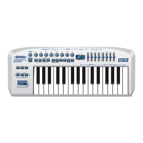
Thank you for purchasing the MIDI keyboard controller PCR-A30.
Before using this unit, carefully read the sections entitled: "USING
THE UNIT SAFELY" and "IMPORTANT NOTES" (OWNER'S
MANUAL p. 2–4). These sections provide important information
concerning the proper operation of the unit. Additionally, in order
to feel assured that you have gained a good grasp of every feature
provided by your new unit, Owner's manual should be read in its
entirety. The manual should be saved and kept on hand as a
convenient reference.
Copyright © 2003 ROLAND CORPORATION
All rights reserved. No part of this publication may be reproduced in
any form without the written permission of ROLAND CORPORATION.
Advertisement
Table of Contents

Related Manuals for Edirol PCR-A30

Summary of Contents for Edirol PCR-A30
- Page 1 Owner’s Manual Thank you for purchasing the MIDI keyboard controller PCR-A30. Before using this unit, carefully read the sections entitled: “USING THE UNIT SAFELY” and “IMPORTANT NOTES” (OWNER’S MANUAL p. 2–4). These sections provide important information concerning the proper operation of the unit. Additionally, in order to feel assured that you have gained a good grasp of every feature provided by your new unit, Owner’s manual should be read in its...
- Page 2 Refer all servicing permanent hearing loss. Do not operate for a long to your retailer, the nearest EDIROL/Roland Service period of time at a high volume level, or at a level Center, or an authorized EDIROL/Roland distributor, that is uncomfortable.
- Page 3 101b • In households with small children, an adult should • The unit and the AC adaptor should be located so provide supervision until the child is capable of their location or position does not interfere with following all the rules essential for the safe their proper ventilation.
-
Page 4: Important Notes
IMPORTANT NOTES In addition to the items listed under “USING THE UNIT SAFELY” on page 2 -3, please read and observe the following: Power Supply Additional Precautions • Do not use this unit on the same power circuit with any device that •... -
Page 5: Contents Of The Package
●USB Audio Interface / MIDI Keyboard Controller PCR-A30 ●AC adaptor This is the only AC adaptor you should use with the PCR-A30. Do not use any AC adaptor other than the supplied one, since doing so may cause malfunction. ●USB cable Use this to connect the USB connector of your computer with the USB connector of the PCR-A30. -
Page 6: Quick Page Reference Table
36 Playing sounds on your computer p. 40 Recording sound on your computer p. 41 Digital recording the output of the PCR-A30 on a CD/MD/DAT p. 42 Using the PCR-A30 as a MIDI Playing a connected sound module p. 43... -
Page 7: Table Of Contents
Quick page reference table ......6 Transmitting a Reset message ........50 Contents............7 Using the PCR-A30 as a MIDI controller ..51 Changing the Memory Sets ........51 Names of things and what they do ....8 Transmitting the current controller values all at once Panel................ -
Page 8: Names Of Things And What They Do
LINK compatible video device, you can enjoy various video effects that are linked to your performance. 4. MEMORY Button Accesses memories that are stored within the PCR-A30. 5. MIDI CH Button Specifies the transmission channel (“current channel”) for the keyboard and bender. - Page 9 13.Display Indicates the current status and various other information. Lights if the PCR-A30 is connected to your computer via USB. DATA OUT This will blink when MIDI messages are transmitted via USB or MIDI OUT. Lights when the value shown in the display is hexadecimal.
-
Page 10: Rear Panel
USB cable. To use the PCR-A30 with bus power, set the power switch to USB. * For some computers, the PCR-A30 may not operate if bus power is used. In this case, use the included AC adaptor. 26.USB connector Use this when connecting the PCR-A30 to your computer via a USB cable. -
Page 11: Setup
Setup This section explains how to install the drivers needed for connecting the PCR-A30 to a computer, and make the necessary settings. Getting Connected and Installing Drivers (Windows)....(p. 12) Getting Connected and Installing Drivers (Macintosh)....(p. 25) What is a driver? A “driver”... -
Page 12: Getting Connected And Installing Drivers (Windows)
Windows XP users If you are using Windows XP Professional, you must With the PCR-A30 disconnected, start up Windows. log on using a user name with an administrative Disconnect all USB cables except for a USB keyboard and USB mouse (if used). - Page 13 3. Use the USB cable to connect the PCR-A30 to your computer. specified. By turning on devices in the wrong order, you risk causing Set the PCR-A30's power switch to the “DC” position, and turn on the malfunction and/or power. damage to speakers and Near the task bar, your computer will indicate “Found New Hardware”.
- Page 14 Getting Connected and Installing Drivers (Windows) Make sure that the “Model” field indicates “EDIROL PCR-A WAVE” or “EDIROL PCR-A MIDI”, and click [Next]. Driver installation will begin. If the “What action do you want Windows to take?” (Step 4) setting was not set to “Ignore”, a “Hardware Installation”...
- Page 15 Select “Don’t search. I will choose the driver to install”, and click [Next]. Make sure that the “Model” field indicates “EDIROL PCR-A WAVE” or “EDIROL PCR-A MIDI”, and click [Next]. Driver installation will begin. If the “What action do you want Windows to take?” (Step 4) setting was not set to “Ignore”, a “Hardware Installation”...
- Page 16 Getting Connected and Installing Drivers (Windows) Enabling background processing In Windows XP, make settings to enable background processing. If you fail to make this setting, you may experience interruptions in the sound. To ensure that MIDI and audio processing occurs smoothly, use the following procedure to make settings.
-
Page 17: Windows 2000 Users
Getting Connected and Installing Drivers (Windows) Windows 2000 users With the PCR-A30 disconnected, start up Windows. Log on to Windows as a Disconnect all USB cables except for a USB keyboard and USB mouse (if used). user with administrative If you are using virus checking or similar software, be sure to exit it as well. - Page 18 3. Use the USB cable to connect the PCR-A30 to your computer. devices in the wrong order, you risk causing malfunction and/or Set the PCR-A30's power switch to the “DC” position, and turn on the damage to speakers and power. other devices.
- Page 19 Getting Connected and Installing Drivers (Windows) The Files Needed dialog box will appear. Input the following into the “Copy files from” field, and click [OK]. (drive name) : \DRIVER\USB_XP2K * The drive name “D:” may be different for your system. Specify the drive name of your CD-ROM drive.
- Page 20 Getting Connected and Installing Drivers (Windows) Enabling background processing In Windows 2000, make settings to enable background processing. If you fail to make this setting, you may experience interruptions in the sound. To ensure that MIDI and audio processing occurs smoothly, use the following procedure to make settings.
- Page 21 3. Use the USB cable to connect the PCR-A30 to your computer. other devices. You may be requested to Set the PCR-A30's power switch to the “DC” position, and turn on the install a USB hub. power. In this case, perform the The driver will be installed automatically.
-
Page 22: Settings And Checking
Click OK to complete the settings. advantage” (p. 24). This completes settings for using the PCR-A30 with an application that uses the standard Windows device settings, such as Media Player. For details on how to make these settings, refer to the owner’s manual for your software. -
Page 23: Windows 98 Users
7. Close the Multimedia Properties dialog box. Click [OK] to complete the settings. This completes settings for using the PCR-A30 with an application that uses the standard Windows device settings, such as Media Player. For details on how to make these settings, refer to the owner’s manual for your software. - Page 24 Buffer Size in the driver settings dialog box. Latency is the time delay from when an application plays back audio data until the sound is actually heard from an audio device such as the PCR-A30. 1. As described in Opening the driver settings dialog box , open the “Driver Settings” dialog box.
-
Page 25: Getting Connected And Installing Drivers (Macintosh)
PCRAUSBDriver.pkg. the installation, input the password and click "OK." The display will indicate “Welcome to the EDIROL PCR-A USB Driver Installer”. Click [Continue]. The display will indicate “Select a Destination”. Click the drive in which the operating system is installed to select it, and then click [Continue]. -
Page 26: Setting The Audio Device
Before using the PCR-A30 with your software, please note the following points. sounds from your Macintosh (including • Turn on the power of the PCR-A30 before you start up your software. audio alerts) will be output • Do not disconnect the USB cable from the PCR-A30 or power-off the only through the PCR-A30, PCR-A30 while your software is running. -
Page 27: Mac Os 9 Users
* Disconnect the PCR-A30 from the Macintosh before you perform the installation. If a PCR-A30 is already connected to your Macintosh when you install the driver, a message like the following will appear when the Macintosh is started up. Perform the steps described below as appropriate for the message that is displayed. -
Page 28: Setting The Driver
3. Use the USB cable to connect the PCR-A30 to your computer. damage to speakers and other devices. Set the PCR-A30's power switch to the “DC” position, and turn on the power. fig.3-3 This unit is equipped with From the CD-ROM, drag the Driver E (Mac OS 9) - OMS a protection circuit. - Page 29 Getting Connected and Installing Drivers (Macintosh) Choose “Open” from the File menu. From the OMS Setting folder that you copied in step 3, select the PCR-A file, and click [Open]. fig.3-8_35 A screen like the one shown here will appear. fig.3-9_35 From the Edit menu, select OMS MIDI Setup.
- Page 30 Next, make MIDI device settings in your sequencer or other software. For details on how to make these settings, refer to the owner’s manual for your software. For details on the PCR-A30’s input/output devices, refer to “Input/output devices” (p. 38).
-
Page 31: Freemidi Settings
Set the PCR-A30's power switch to the “DC” position, and turn on the power. This unit is equipped with From the CD-ROM, drag the PCR-A30 Driver E (Mac OS 9) - FreeMIDI a protection circuit. - Page 32 Next, make MIDI device settings in your sequencer or other software. For details on how to make these settings, refer to the owner’s manual for your software. For details on the PCR-A30’s input/output devices, refer to “Input/output devices” (p. 38).
-
Page 33: Installing The Asio Driver
Getting Connected and Installing Drivers (Macintosh) ■ Installing the ASIO driver You must install the PCR-A30 driver even if you will be using only audio on the PCR-A30. Be sure to install the PCR-A30 driver before you install the ASIO driver. - Page 34 Buffer Size in the driver settings dialog box. Latency is the time delay from when an application plays back audio data until the sound is actually heard from an audio device such as the PCR-A30. 1. As described in “Opening the driver settings dialog box” (p. 34), open the “Driver Settings”...
-
Page 35: Operation
Operation The PCR-A30 is a controller that transmits MIDI messages. You cannot perform using only the PCR-A30 by itself. You will need to connect it to a sound module or computer. The various controllers ([R1--R8], [S1--S8], [B1--B6], [L1--L3], [P1, P2]) can be assigned almost any message you want to get the control you need for your particular setup. -
Page 36: Basic Use
If you connect as shown in the diagram, you will be able to monitor the playback from your software or the sound from instruments or audio devices connected to the PCR-A30. Audio and MIDI flow ■Audio flow (Block diagram) -
Page 37: Midi Flow
MIDI sound module (sold separately) MIDI OUT PCR-A30 As seen from the PCR-A30, each section in the diagram will be as follows BULK RECEPTION BULK data is received here MIDI OUT Of the keyboard, bender lever, and other controllers, those... -
Page 38: Input/Output Devices
For details on these settings, refer to the owner’s manual for your software. * If you are unable to select the PCR-A30 in the device settings for your software, it is possible that the PCR- A30 driver was not installed correctly. Please reinstall the driver. -
Page 39: Two Midi Ports
The output destination of the MIDI messages transmitted when you operate the PCR-A30’s faders, knobs, and buttons can be specified separately for each controller. (➝“Assign MIDI messages... -
Page 40: Use Audio Functionality
To prevent malfunction and/or damage to speakers or other devices, always turn down the volume, and turn off the power on all devices before making any connections. The PCR-A30 is not equipped with its own MIDI sound generator. This means that MIDI data from your computer cannot be played by the PCR-A30... -
Page 41: Recording Sound On Your Computer
LINE IN If the PCR-A30 is connected as shown above to a device that outputs (“thru-s”) the input audio (such as a cassette player that is in recording mode), turning on the Input monitor switch will cause the sound to loop between the PCR-A30 and the other device, causing oscillation and producing an unexpectedly high volume. -
Page 42: Digitally Recording Sound From Your Computer
The PCR-A30 does not support professional digital audio formats. The PCR-A30 is not able to output the input signal from its input jacks directly to its digital output jack. The digital output jack always output only the audio signal that is being sent from your computer. -
Page 43: Using The Pcr-A30 As A Midi Keyboard
MIDI flow MIDI OUT If you want to use the PCR-A30 as a MIDI keyboard, don't connect the USB cable. While you have a USB cable connected, MIDI messages won't be transmitted from the PCR-A30's MIDI OUT connector when you play its keyboard (see “MIDI flow” (p. 37)). -
Page 44: Expression P
● To switch the PCR-A30 to PLAY mode... The PCR-A30 will automatically start up in PLAY mode when you turn on the power. To return to PLAY mode from another mode (“Table of operating modes” (p. 45)), press the button of the current mode (i.e., the button that is lit). -
Page 45: Table Of Operating Modes
You can switch modes at any time, as shown below. Mode Switching modes Explanation Transmit MIDI messages by When you turn on the power, the PCR-A30 will PLAY mode playing the keyboard or (p. 44) start up in PLAY mode. -
Page 46: Setting The Midi Transmit Channel
Using the PCR-A30 as a MIDI keyboard Setting the MIDI Transmit Channel To control the sound module, set the MIDI channel the PCR-A30 will use to transmit on to the same channel the modules is using to receive on. Use MIDI Channel mode to set the MIDI transmit channel. - Page 47 If you are not in Play mode, you can use one of two ways to input a numerical value into the PCR-A30; Decimal input mode or Hexadecimal input mode. If you want to input decimal numbers, press the [DECIMAL] button. If you want to input hexadecimal numbers, press the [HEX] button.
-
Page 48: Selecting Sounds On A Sound Module
Using the PCR-A30 as a MIDI keyboard Selecting Sounds on a Sound Module (Sending Program Change / Bank Select Massages) To select a sound on your MIDI sound module, transmit a Program Change in Program Change mode. To select a sound from a different bank, first use Bank mode to transmit a Bank Select message that switches the bank. - Page 49 Using the PCR-A30 as a MIDI keyboard ●Bank mode (BANK) This mode lets you transmit a bank select (MSB, LSB) message on the current channel. The program change message you most recently transmitted (specified) in Program Change mode (p. 48) will also be transmitted following the bank select message.
-
Page 50: Transmitting A Reset Message
Using the PCR-A30 as a MIDI keyboard Transmitting a Reset message (What to do if there are "stuck" MIDI notes) If notes on a connected MIDI sound module become “stuck”, or if there is something wrong with the sound, you can execute the Panic function to solve the problem. -
Page 51: Using The Pcr-A30 As A Midi Controller
* If you edit the controller settings of a memory you recall, and want to keep your changes, you must save the memory before powering down the PCR-A30. For the procedure, refer to “Saving a memory set (SAVE)” (p. 76). -
Page 52: Transmitting The Current Controller Values All At Once (Snapshot)
Using the PCR-A30 as a MIDI controller Transmitting the current controller values all at once (SNAPSHOT) Once you have set the various controllers to the desired settings, you can transmit a detailed description of this state in the form of a “snapshot”. When you execute this function, the current values of the controllers ([R1–R8], [S1–S8]) will be transmitted. -
Page 53: Assign Midi Messages (Edit)
Using the PCR-A30 as a MIDI controller Assign MIDI messages (EDIT) You can assign the following functions to a controller. You will use Edit mode to assign MIDI messages. NOTE NOTE ASSIGN (p. 55) You can copy assigned messages to AFTERTOUCH AFTERTOUCH ASSIGN (p. - Page 54 Messages will be sent to both “PCR-A 1” and “PCR-A 2” 2. Press the [ENTER] button. If you are using the PCR-A30 with a MIDI connection, the messages will be transmitted from the MIDI OUT connector regardless of this port setting.
-
Page 55: Note Assign
Using the PCR-A30 as a MIDI controller ■ NOTE ASSIGN Here’s how to assign a Note message to a controller. In addition to being used to play sounds, note messages can also be used to control a sequencer. Mode Keyboard... -
Page 56: Advanced Mode
Using the PCR-A30 as a MIDI controller Advanced mode 1 Advanced mode 1 of NOTE ASSIGN lets you specify the velocity value in addition to the items of Basic mode. 1. Press the [EDIT] button. 2. Slightly move the controller to which you want to assign a Note message. In the case of a button, press that button. -
Page 57: Aftertouch Assign
Using the PCR-A30 as a MIDI controller ■ AFTERTOUCH ASSIGN Here’s how to assign an Aftertouch message to a controller. Mode Keyboard Message Value range Port Basic mode Channel Pressure 0-127 (00–7FH) Port 1 Advanced mode 1 Channel Pressure Assignable... - Page 58 Using the PCR-A30 as a MIDI controller Advanced mode 1–3 Advanced mode 1 of AFTERTOUCH ASSIGN lets you specify the upper and lower limits of the aftertouch value in addition to the items of Basic mode. Advanced modes 2 and 3 let you specify an aftertouch message for an individual note (Polyphonic Key Pressure) instead of specifying the channel.
-
Page 59: Control Change Assign
Using the PCR-A30 as a MIDI controller ■ CONTROL CHANGE ASSIGN Here’s how to assign a control change message to a controller. Mode keyboard Value range Port Basic mode 00–7FH PORT 1 Advanced mode 1 Assignable Assignable Advanced mode 2... - Page 60 Using the PCR-A30 as a MIDI controller Advanced mode 1 Advanced mode 1 of CONTROL CHANGE ASSIGN lets you specify the upper and lower limits of the control change value in addition to the items of Basic mode. 1. Press the [EDIT] button.
-
Page 61: Program Change Assign
Using the PCR-A30 as a MIDI controller ■ PROGRAM CHANGE ASSIGN Here’s how to assign a program change message to a controller. Mode Number Effect Bank Port Basic mode Fixed value Not output PORT 1 Advanced mode 1 Assignable range of values... - Page 62 Using the PCR-A30 as a MIDI controller Advance mode 1, 2 Advanced mode 1 of PROGRAM CHANGE ASSIGN lets you specify the upper and lower limits of the program change value. Advanced mode 2 lets you transmit BANK LSB/MSB settings in addition to the program change.
- Page 63 Using the PCR-A30 as a MIDI controller Advanced modes 3 and 4 Advanced mode 3 lets you assign the Program Change Decrement function (PC DEC) to a controller. Advanced mode 4 lets you assign the Program Change Increment function (PC INC) to a controller.
-
Page 64: Rpn/Nrpn Assign
Using the PCR-A30 as a MIDI controller ■ RPN/NRPN ASSIGN Here’s how you can assign an RPN or NRPN message to a controller. Data entry MSB Data entry LSB Mode Keyboard Port (CC#6) range (CC#38) range Basic mode 0-127 (00–7FH) - Page 65 Using the PCR-A30 as a MIDI controller Advanced mode In Advanced mode for RPN/NRPN, you can specify the upper and lower limit of the data entry MSB (CC#6) value when the RPN/NRPN message is transmitted, as well as the various settings available in Basic mode.
-
Page 66: Sys Ex. Assign
Using the PCR-A30 as a MIDI controller ■ Sys Ex. ASSIGN Here’s how you can assign a system exclusive message to a controller. Advanced mode 2 lets you assign a single-byte system message (System realtime message, tune request). Advanced modes 3 and 4 let you assign any desired message. (Input up to 24 bytes) - Page 67 11. Input the second and subsequent bytes in the same way. 12. After you have input the number of bytes you specified in step 7, the PCR-A30 will check whether the messages you've input are indeed valid MIDI messages. If there is a problem, the display will indicate “ERR”.
- Page 68 Sys Ex. ASSIGN items ● Specifying the checksum The PCR-A30 can automatically calculate the checksum of a system exclusive message and embed it in the message. In order to use this function, you must use the following procedure to specify the starting location from which the checksum is calculated, and the location at which the checksum is inserted.
- Page 69 For the channel and block number, the setting of the current channel will be inserted as the lower bits. (The block number is not actually a channel, but corresponds to the “part” within a GS sound module. On the PCR-A30, this corresponds to the channel for the sake of convenience.)
-
Page 70: Examples Of Assigning System Exclusive Messages
Using the PCR-A30 as a MIDI controller Examples of assigning system exclusive messages ● GM2 System On F0 7E 7F 09 03 F7 Here’s how to assign a GM2 System On system exclusive message in Basic mode. 1. Press the [EDIT] button. -
Page 71: Master Volume
Using the PCR-A30 as a MIDI controller ● Master Volume F0 7F 7F 04 01 vL vM F7 Since a Master Volume message has a data range of 00 00–7F 7F and we do not need to specify the range, we will use Basic mode. Since the two bytes of data are in the order of LSB and then MSB, we will select “DT3”... - Page 72 Using the PCR-A30 as a MIDI controller ● Bend Pitch Control fig.checksum Since the GS Bend Pitch Control message has a data Block number 1 byte range of 40H–58H (0–24 semitones), we will select F0 41 10 42 12 40 2x 10 DATA SUM F7 Advanced mode 1, which lets us specify the range.
-
Page 73: Tempo Assign
Using the PCR-A30 as a MIDI controller ■ TEMPO ASSIGN You can assign a controller to adjust the speed (20–250) of the F8 Clock message. * In order to transmit F8 Clock messages, the F8 CLOCK setting must be “ON”. -
Page 74: Copying A Midi Message Assignment (Assign Copy)
Using the PCR-A30 as a MIDI controller Copying a MIDI message assignment (ASSIGN COPY) Here’s how a message assigned to a controller can be copied to another controller. fig.edt Press the [EDIT] button. The display will indicate “EDT”. Slightly move the controller to which you want to copy the assignment (the “copy destination”). -
Page 75: Canceling A Midi Message Assignment (No Assign)
Using the PCR-A30 as a MIDI controller Canceling a MIDI message assignment (NO ASSIGN) Here’s how you can cancel the message assigned to a controller. Once its assignment is cancelled, no message will be transmitted when you operate that particular controller. -
Page 76: Saving A Memory Set (Save)
Using the PCR-A30 as a MIDI controller Saving a memory set (SAVE) Here’s how to save the settings of the current memory into internal memory. You can save settings into internal memory numbers 1–F. You cannot save to memory number 0 (GM2). -
Page 77: Transmitting/Receiving Bulk Data (Bulk)
All memories will be received as bulk data. ALL BULK The received data will overwrite memories 1–F. Confirm what’s indicated and press the [ENTER] button. fig.rs1 The third digit of the display will blink, and the PCR-A30 will wait to receive bulk data. - Page 78 Using the PCR-A30 as a MIDI controller ● About the display in Bulk mode fig.bulk-dis Waiting to receive Receive SINGLE (blinking) BULK 1st digit: indicates Receive mode or 3rd digit: indicates Transmit mode Transmit Waiting to transmit Transmitting/Receiving/Waiting states BULK...
- Page 79 Confirm what’s indicated and press the [ENTER] button. fig.bs-1 The third digit of the display will blink, and the PCR-A30 will wait to transmit bulk data. Press the [ENTER] button. On your sequencer software, specify “PCR -A 2” as the MIDI input device. For details on this setting, refer to the manual of your sequencer software.
-
Page 80: Protecting A Memory Set (Protect)
Using the PCR-A30 as a MIDI controller Protecting a memory set (PROTECT) If you turn the Protect setting ON, All Bulk (p. 77) reception and Save (p. 76) operations will be disabled. fig.edt Press the [EDIT] button. The display will indicate “EDT”. -
Page 81: V-Link Mode
Using the PCR-A30 as a MIDI controller V-LINK mode When you press the [V-LINK] button, the Pro- Bank PCR will transmit a V-LINK ON message Note Number gram Select and will enter V-LINK mode. When you Change press the [V-LINK] button once again, the PCR will transmit a V-LINK OFF message and will exit V-LINK mode. -
Page 82: System Settings
System settings ●SYSTEM Here’s how you can make various system settings for the PCR-A30. fig.edt Press the [EDIT] button. The display will indicate “EDT”. Press the [SYSTEM] key. The display will indicate “SY0”. fig.sy0 Use the [0]–[8] , [A]–[E] keys to specify the System setting that you want to set, and then press the [ENTER] button. -
Page 83: F8 Clock Default Tempo
System settings ■ F8 CLOCK ON / OFF (Keyboard : 0) Perform steps 1–3. 4. Use the [DEC][INC] buttons or the [0] or [1] keys to switch F8 CLOCK on/off. The display will indicate either “ON” or “OFF”. 5. Press the [ENTER] button. ■... -
Page 84: Startup Memory
48kHz (ADVANCE) In Advanced mode, audio signals can be transferred between the PCR-A30 and the computer at a resolution of 24 bits and sampling frequencies of 44.1 / 48 / 96 kHz. Select this mode if you are using... - Page 85 4. Use the [DEC][INC] buttons or the [0] - [2] keys to switch DIRECT MONITOR on/off. The input signal from the audio input jacks will not be sent to the PCR-A30's speakers, headphone jack, or master output jacks. Settings or operations in your ASIO 2.0 application (e.g., Cubase) will switch Direct Monitor on/off.
- Page 86 MEMO...
-
Page 87: Appendices
Appendices This section contains troubleshooting information and explanations of convenient functions. You may read this material as necessary. Memory sets ................p. 88 Troubleshooting..............p. 94 MIDI implementation ............p. 101 Main specifications ............... p. 106... -
Page 88: Memory Sets
Memory sets With the factory settings, the GM2 set shown in the illustration is assigned to the controllers. Use the included template. The following memory sets are also provided. GM2 set (MEMORY: 0) ..........(p. 88) H-COMPATIBLE (ProTools LE, Digital Performer 3) SET MCR-8 MODE 3 (SONAR 2) SET......(p. - Page 89 Memory sets ■ MCR-8 MODE 3 (SONAR 2) SET When using this memory set, turn the PCR-A30's OMNI (p. 47) setting OFF. MCR-8 MODE 3 (SONAR 2) - A (MEMORY: 1) MCR-8 MODE 3 (SONAR 2) - B (MEMORY: 2)
-
Page 90: Memory Sets
Memory sets ■ MCR-8 MODE 4 (Cubase 5/SX) SET When using this memory set, turn the PCR-A30's OMNI (p. 47) setting OFF. MCR-8 MODE 4 (Cubase 5/SX) - A (MEMORY: 5) MCR-8 MODE 4 (Cubase 5/SX) - B (MEMORY: 6) - Page 91 0(00) / 127(7F) EXPRESSION CC 11(0B) 0(00) - 127(7F) ■ GS SET When using this memory set, you will find it convenient to turn the PCR-A30's OMNI (p. 47) setting ON. GS-A (MEMORY: A) Parameter Message (Hex.) Range (Hex.)) Port...
- Page 92 Memory sets GS-B (MEMORY: B) Parameter Message (Hex.) Range (Hex.) Port CHORUS MACRO F0 41 10 42 12 40 01 38 dd SUM F7 0(00) - 7(07) CHORUS PRE-LPF F0 41 10 42 12 40 01 39 dd SUM F7 0(00) - 7(07) CHORUS DELAY F0 41 10 42 12 40 01 3C dd SUM F7...
- Page 93 Memory sets ■ XG SET When using this memory set, you will find it convenient to turn the PCR-A30's OMNI (p. 47) setting ON. XG-A (MEMORY: D) Parameter Message (Hex.) Range (Hex.) Port BEND PITCH CONTROL F0 43 10 4C 08 0ch 23 dd F7...
-
Page 94: Troubleshooting
Did you make the correct connections and settings for installation? Check each one of the following items. • Is the PCR-A30 connected correctly? Make sure that the USB connector of your computer is connected to the PCR-A30 by a USB cable. • Is the PCR-A30's power switch set to DC? - Page 95 The power conservation mode of your computer may limit the power that is supplied to USB. Check the settings of your computer. • In some cases, the PCR-A30 cannot be used with a bus-powered hub (a hub that does not contain a power supply). Please use a self-powered hub (a hub that contains a power supply). •...
-
Page 96: Deleting The Driver
Macintosh. If it is still not detected, shut down your Macintosh, and then restart it. • In some cases, the PCR-A30 will not be detected if you have connected it to the USB connector located on the keyboard of the Macintosh. Please connect it to a USB connector on the Macintosh itself. - Page 97 Is a mic or guitar still connected? If a mic or guitar is connected to the PCR-A30, disconnect the mic or guitar, and turn the Gain knob all the way to the left.Disconnect any audio devices you are not using.
- Page 98 Troubleshooting Does your sequencer software support ASIO 2.0 or 24-bit audio? If your ASIO-compatible software does not support ASIO 2.0, it will not operate correctly if you use [PCR-A ASIO2.0 16bit] or [PCR-A ASIO2.0 24bit] as the ASIO driver. In this case, select either [PCR-A ASIO1.0 16bit] or [PCR-A ASIO1.0 24bit] as the ASIO driver. If your ASIO-compatible software does not support 24-bit audio input/output, it will not operate correctly if you select [PCR-A ASIO1.0 24bit] or [PCR-A ASIO2.0 24bit] as the ASIO driver.
- Page 99 Was a heavy processing load experienced while using the PCR-A30, such as accessing the CD-ROM drive or a network? If an operation involving a heavy processing load is performed while the PCR-A30 is in use, it may not operate correctly. If this occurs, stop playback/recording, and then try resuming playback/recording. If you are still unable to play back/record, exit all applications that use the PCR-A30, switch off the PCR-A30, then turn it on again.
- Page 100 Was the driver installed correctly? In order for you to play back audio data via the PCR-A30, the driver must be installed. For installation and settings, refer to “Getting Connected and Installing Drivers” (Windows, p. 12 / Macintosh, p. 25).
-
Page 101: Midi Implementation
●Note on Status 2nd byte 3rd byte ●Data transmission The PCR-A30 can use Bulk Dump (p. 104) to transfer its internal memory set data (p. 88). n = MIDI channel number: 0H – FH (Ch.1 – 16) kk = note number: 00H –... -
Page 102: Program Change
■ System common message ●Program change Status 2nd byte On the PCR-A30 you can assign the following system common messages to any controller and transmit them. n = MIDI channel number: 0H – FH (Ch.1 – 16) ●MTC quarter frame pp = Program number: 00H –... -
Page 103: System Exclusive Message
MIDI implementation ■ System exclusive message ❍Sender Model Name Transmitted when entering V-LINK mode. The PCR-A30 is able to transmit the following exclusive messages: exclusive Status Data byte Status messages assigned to the controllers, Identity Reply, V-LINK messages, and Bulk 41H,10H,00H,51H,12H, Dump. -
Page 104: Supplementary Material
500 ms. <Example4> What is the nibble-expressed value of decimal 1258? * Please be aware that if you modify the data dumped from the PCR-A30 by 1258 ÷ 16 = 78 (quotient) ... 10 (remainder) changing the order in which the exclusive messages are transmitted, by 78 ÷... -
Page 105: Midi Implementation Chart
MIDI implementation USB AUDIO INTERFACE / Date : Oct. 1, 2003 MIDI KEYBOARD CONTROLLER MIDI Implementation Chart Version : 1.00 Model PCR-A30 Transmitted Recognized Function... Remarks Basic Default Channel Changed 1–16 Default Mode 3 Mode Messages OMNI ON/OFF, MONO, POLY... -
Page 106: Main Specifications
Main specifications PCR-A30: USB Audio Interface / MIDI Keyboard Controller ●Number of Audio Record/Playback Channels Pitch Bend/Modulation Lever Assignable Rotary Volume Kbobs (R1--8) Record: 1 pair of stereo Assignable Sliders (S1--8) Playback: 1 pair of stereo Assignable Pedals (P1, P2) Full duplex (except for 96 kHz setting) ●Display... -
Page 107: Index
........12, 17 Driver Signing Options ..........72 Bend Pitch Control ..........9, 44 BENDER Lever ..............69 Block ............. 38 EDIROL PCR-A ..........24, 34, 99 Buffer Size ............... 53 EDIT ..............77 BULK ............. 8 EDIT Button ................. 10 .......... - Page 108 ........38 MME EDIROL PCR-A In ........38 MME EDIROL PCR-A Out ............83 Generic driver ............ 44, 101 Modulation ..............88 GM2 set ............... 49 ............. 70 GM2 System On ..........102 MTC quarter frame ..............91 GS SET ............
- Page 109 index ................ 64 ............103 V-LINK ON ..........64 RPN/NRPN ASSIGN ............38 WDM driver ......41, 84 SAMPLING FREQUENCY ..............76 SAVE ......... 76 Saving a memory set (SAVE) ..........77, 79 SINGLE BULK ............52 SNAPSHOT ....... 52 Snapshot mode (SNAPSHOT) ..............
- Page 110 MEMO...
-
Page 111: Declaration Of Conformity
Compliance Information Statement Model Name : PCR-A30 Type of Equipment : USB AUDIO INTERFACE/MIDI KEYBOARD CONTROLLER Responsible Party : Edirol Corporation North America Address : 425 Sequoia Drive, Suite 114, Bellingham, WA 98226 Telephone : (360) 594-4276 For the U.K. - Page 112 Information When you need repair service, call your nearest EDIROL/Roland Service Center or authorized EDIROL/Roland distributor in your country as shown below. IRELAND HONG KONG BARBADOS PERU CYPRUS Roland Ireland Parsons Music Ltd. A&B Music Supplies LTD Audionet Radex Sound Equipment Ltd.
Need help?
Do you have a question about the PCR-A30 and is the answer not in the manual?
Questions and answers