
Related Manuals for Hunter 80707


Summary of Contents for Hunter 80707
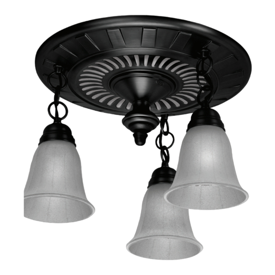
- Page 1 The Garden District Collection Bath Ventilator with Light Owner’s Manual Model 80707 43053-01 20110908 ©2011 Hunter Fan Co.
-
Page 2: Cooking Area
MAINTENANCE The motor is permanently lubricated and never needs oiling. If the motor bearings are making excessive or unusual TO REDUCE THE RISK OF FIRE, ELECTRIC SHOCK, OR noises, replace the motor with the exact service motor. You should INJURY TO PERSONS, OBSERVE THE FOLLOWING: replace the impeller at the same time. - Page 3 Check all the parts. If damaged, call 1-888-830-1326 for replacements. Extra Screws 3/8” Cable Connector NOTE: Strain relief cable connector must be installed. Not Included. 95044-01-000 95029-01-000 77481-01-000 03242-07-133 98624-01-000 74508-53-000 77521-01-000 74508-53-000 98447-02-000 66534-01-000 98617-01-000 66534-01-000 98519-02-000 77480-01-218 88401-02-000 65517-01-000 88432-01-000 Not included...
-
Page 4: Before Installation
Before Installation NOTE: Remove all packing materials before installation. Loosen screws. Turn off the power source. Remove the motor/blower from the housing. Remove packing material. Remove the pre-loaded screw tip covers. Back out the pre-loaded screw tips until flush with the side of the housing. - Page 5 Remove the wiring cover screw. Remove the wiring cover. Pop out the first wiring access slug. Use second if needed. Insert the strain relief into the housing and secure with the washer. Choose Installation Option For New Construction - attaching to joist go to step A11, page 7 For New Construction - suspended between joists go to step B11, page 9 For Existing Construction - accessible from above go to step C11, page 12 For Existing Construction - accessible only from below go to step D11, page 16...
- Page 6 New construction attaching to joist Screw pre-loaded screws into joist or framing. Position the correct depth mark at the bottom edge of the joist based on the thickness of your sheetrock. Pull wires through the strain relief. Go to step F1 on page 20 to connect the wires as shown. Install the wiring cover plate.
- Page 7 0 0 0 0 0 0 0 0 Connect wiring from the motor to the wiring cover plate. Reinstall the motor by inserting the tabs and pushing up into position. Make sure the wires are not pinched between the motor and the housing. Turn on the power source.
- Page 8 New construction suspended between joist Position the correct depth mark at the bottom edge of the Slide the mounting rails into brackets. joist based on the thickness of your sheetrock. 1/8" Bit Mark position of screws by using holes as a template. Drill a hole in the center of each outline.
- Page 9 Tighten screws. Install the wiring cover plate. Make sure all wiring connections are inside the box or under the wiring cover plate. Go to step F1 on page 20 to connect the wires as shown. Install the wiring cover plate. Make sure all wiring connections are inside the box or under the wiring cover plate..
- Page 10 Secure the motor by tightening the 2 screws. Reinstall the motor by inserting the tabs and pushing up into position. Make sure the wires are not pinched between the motor and the housing. Test the motor. If the motor does not run, check the Turn on the power source.
- Page 11 Existing construction accessible from above EXISTING FAN NO EXISTING FAN Remove an existing fan and check to make sure the opening is Use the motor housing as a template to mark position. large enough to accommodate the new motor housing (8”x 8.5”). Slide the mounting rails into brackets.
- Page 12 1/8" Bit Drill a hole in the center of each outline. Insert screws, leaving space between the screw head and the joist. Screws are not provided. Attach the rails onto the screws. Tighten screws. Connect 4” duct and vent to the outside. Tape joints. If ducting Pull wires through the strain relief.
- Page 13 Go to step F1 on page 20 to connect the wires as shown. Tighten the strain relief screws. Install the wiring cover plate. Make sure all wiring connections Connect wiring from motor the motor are inside the box or under the wiring cover plate. to the wiring cover plate.
- Page 14 Turn on the power source. Test the motor. If the motor does not run, check the plug connection. Go to step E1 on page 18 to attach grill. 43053-01 - 09/12/2011...
- Page 15 Existing construction accessible only from below EXISTING FAN Move the housing into position above the ceiling. Remove an existing fan and check to make sure the opening is large enough to accommodate the new motor housing (8”x 8.5”). Attach existing ducting to duct connector. Tape joints. If ducting Pull wires through strain relief.
- Page 16 Install the wiring cover plate. Connect wiring from the motor to the wiring cover plate. Reinstall the motor by inserting the tabs and pushing up into Secure the motor by tightening the 2 screws. position. Make sure the wires are not pinched between the motor and the housing.
- Page 17 Attaching the grill NOTE: The grill’s size, shape, and number of lights may vary. Remove the two star nuts. Align posts B and D (stamped into motor housing) with posts B and D (stamped into light fixture). Slide support bar and hiding plate onto posts.
-
Page 18: Wiring The Fan
Screw finial onto the threaded rod of the support bracket. Unscrew glass retainer ring using the glass ring tool provided. Place the glass onto the sockets and re-install the glass Complete. retaining rings using the glass ring tool. Wiring the fan Ground Black Green... -
Page 19: Troubleshooting
Problem: Fan does not come on. Solution: • Hunter Fan Bath Ventilators are extremely quiet. To confirm that the fan is running, place your hand near the vents to feel the air movement. • Turn power on, replace fuse, or reset breaker. -
Page 20: Warranty
If your Hunter Fan bath exhaust fan motor fails at any time within five years after the date of sale to you due to a defect in material or work- manship, labor and materials to repair the defect will be provided free of charge. - Page 21 The Garden District Collection Ventilador para baño con luz Manual del Propietario Modelo 80707 43053-02 20110909 ©2011 Hunter Fan Co.
-
Page 22: Mantenimiento Preventivo
ventilador, el motor/soplador y el interior del alojamiento. A D V E R T E N C I A LAS PARTES METÁLICAS ELÉCTRICAS NUNCA DEBEN PARA REDUCIR EL RIESGO DE INCENDIO, CHOQUE ELÉCTRICO SUMERGIRSE EN AGUA. MANTENIMIENTO O LESIONES A PERSONAS, OBSERVE LO SIGUIENTE: 1. - Page 23 Verifique todos los componentes. Si están dañados, llame al 1-866-405-3814 para obtener un reemplazo. Tornillos adicionales Conector de cable de 3/8” NOTA: Debe estar instalado el manguito de alivio de tensión del cable. No incluido. 95044-01-000 95029-01-000 77481-01-000 03242-07-133 98624-01-000 74508-53-000 77521-01-000 74508-53-000...
-
Page 24: Antes De La Instalación
Antes de la instalación NOTA: Retire todo el material de embalaje antes de la instalación. Apague la fuente de alimentación. Afloje los tornillos. Retirer le moteur/souffleur du boîtier. Retire el material de embalaje. Retire las cubiertas de las puntas de tornillo precargadas. Retire las puntas de tornillo precargadas hasta que estén a nivel con el lado del alojamiento. - Page 25 Retire el tornillo de la cubierta del cableado. Retire la cubierta del cableado. Retire el primer tapón metálico de acceso del cableado. Utilice Inserte el manguito de alivio de tensión (no se incluye) en la caja y sujételo firmemente con una arandela. el segundo si es necesario.
- Page 26 Construcción nueva fijación a la viga Ubique la correcta marca de profundidad en el borde inferior de Instale los tornillos precargados en la viga o el marco. la viga, según el espesor de su plancha de yeso. Vaya al paso F1 en la página 20 para onnectoer les fils tel Tienda los cables a través del manguito de alivio de tension.
- Page 27 0 0 0 0 0 0 0 0 Conecte el mazo de cables. NO PERMITA QUE EL Vuelva a instalar el motor/soplador introduciendo las pestañas MOTOR/SOPLADOR CUELGUE DEL MAZO DE CABLES. y levantando a su posición. Asegúrese que los alambres no se pellizquen entre el motorsoplador y el alojamiento.
- Page 28 New construction suspended between joist Deslice los rieles de montaje en los soportes. Ubique la correcta marca de profundidad en el borde inferior de la viga, según el espesor de su plancha de yeso. 1/8" Bit Marque la posición de los tornillos utilizando los agujeros Marque la posición de los tornillos utilizando los agujeros como como una plantilla.
- Page 29 Apriete los tornillos. Instale la placa de cubierta del cableado. Asegúrese que todas las conexiones de cableado estén dentro de la caja o debajo de la placa de cubierta del cableado. Vaya al paso F1 en la página 20 para onnectoer les fils tel Instale la placa de cubierta del cableado.
- Page 30 Asegure el motor/soplador apretando los 2 tornillos. Vuelva a instalar el motor/soplador introduciendo las pestañas y levantando a su posición. Asegúrese que los alambres no se pellizquen entre el motor/soplador y el alojamiento. Encienda la fuente de alimentación. Pruebe el motor/soplador. Si el motor/soplador no funciona, verifique la conexión del enchufe.
- Page 31 Construcción existente accesible desde arriba VENTILADOR EXISTENTE SIN VENTILADOR EXISTENTE Retire el ventilador existente y asegúrese que la abertura sea Utilice el alojamiento del motor/soplador como una plantilla suficientemente grande para acomodar el alojamiento del para marcar la posición. motor/soplador nuevo (8 pulg. x 8 1/2 pulg.). Recorte una abertura para el alojamiento.
- Page 32 1/8" Bit Taladre un agujero en el centro de cada perfil. Introduzca los tornillos, dejando espacio entre la cabeza del tornillo y la viga. No se proporcionan los tornillos. Fije los rieles con los tornillos. Apriete los tornillos. Tienda los cables a través del manguito de alivio de tension. Conecte un ducto de 4”...
- Page 33 Apriete los tornillos del aliviador de tensiones. Vaya al paso F1 en la página 20 para onnectoer les fils tel qu’indequé comme indiqué. Instale la placa de cubierta del cableado. Asegúrese que todas Conecte el mazo de cables. NO PERMITA QUE EL MOTOR/ las conexiones de cableado estén dentro de la caja o debajo de SOPLADOR CUELGUE DEL MAZO DE CABLES.
- Page 34 Pruebe el motor/soplador. Si el motor/soplador no funciona, Encienda la fuente de alimentación. verifique la conexión del enchufe. Vaya al paso E1 en la página 18 para fijar la rejilla. 43053-02 - 09/14/2011...
- Page 35 Construcción existente accesible sólo desde abajo EXISTING FAN Mueva el alojamiento a su posición encima del techo. Retire el ventilador existente y asegúrese que la abertura sea suficientemente grande para acomodar el alojamiento del motor/soplador nuevo (8 pulg. x 8 1/2 pulg.). Conecte el ducto existente con el conector de ducto.
- Page 36 Instale la placa de cubierta del cableado. Asegúrese que todas Conecte el mazo de cables. NO PERMITA QUE EL MOTOR/ las conexiones de cableado estén dentro de la caja o debajo de SOPLADOR CUELGUE DEL MAZO DE CABLES. la placa de cubierta del cableado. Vuelva a instalar el motor/soplador introduciendo las pestañas Asegure el motor/soplador apretando los 2 tornillos.
- Page 37 Fijar la rejilla NOTA: El tamaño, forma y color de los artefactos puede variar. Retire las dos tuercas de estrella. Alinee los postes B y D (estampados en el alojamiento del motor) con los postes B y D (estampados en el artefacto de iluminación). Deslice la barra de soporte y la placa encubridora hasta los postes.
-
Page 38: Cableado Del Ventilador
Enrosque la cubierta ornamental en la varilla roscada del Desenrosque el anillo de retención de la pantalla usando la soporte de apoyo. herramienta para el anillo suministrada. Completo. Coloque la pantalla en los portalámparas y reinstale los anillos de retención de la pantalla usando la herramienta para el anillo. Cableado del ventilador Tierra Negro... -
Page 39: Solución De Problemas
Problema: El ventilador no está Solución: operando. • Los ventiladores de baño Hunter Fan son muy silenciosos. Para confirmar que el ventilador esté funcionando, coloque su mano cerca de los conductos de ventilación para sentir el movimiento del aire. • Encienda la alimentación eléctrica, reemplace el fusible o restablezca el interruptor automático. - Page 40 Vous devrez assumer les frais d’assurance et de transport à notre usine ou à notre centre de service. Nous vous retournerons votre ventila- teur de salle de bain Hunter Fan en port prépayé. Votre ventilateur de calle de bain devra être emballé avec soin pour éviter tout dommage durant le transport puisque nous ne pourrons être tenus responsables d’un tel dommage.
Need help?
Do you have a question about the 80707 and is the answer not in the manual?
Questions and answers