Advertisement
Available languages
Available languages
Quick Links
Operating Instructions & Parts Manual
Please read and save these instructions. Read carefully before attempting to assemble, install, operate or maintain
the product described. Protect yourself and others by observing all safety information. Failure to comply could result
in personal injury and/or property damage! Save these instructions for future reference.
NOTE: All wiring must be run in accordance with the National Electrical Code (Canadian Electrical Code in Canada) through conduit or
another acceptable means. Contact a qualifi ed electrician if there is any question as to the suitability of the system.
Lamp in Fixture Contains Mercury. Dispose According
to Local, State, or Federal Laws.
WARNING: Turn power off at the fuse or circuit
breaker.
1. Select a location on a fl at wall with structurally sound wood and
from 10 to 25 feet from the ground. The wood should be at least
one inch thick to safely secure the fi xture.
2. Attach the cover plate using two large machine screws.
3. Using the mounting bracket as a template. Hold it at the desired
mounting location (making sure the bottom is level), and mark
four mounting holes. We suggest drilling 3/16" pilot holes for the
lag screws.
4. Put the two top lag screws through their holes in the mounting
bracket and hold them in place while you push the gasket onto
these lag screws. Start these two screws into the two top pilot
holes.
5. Start the other two lag screws, and then tighten all four screws.
6. Hang the fi xture on the mounting bracket using the slot in the
cover plate.
7. Twist the fi xture wires to the supply wires. (black to black, white
to white, and the bare fi xture wire to the supply ground
wire).
8. Make sure the wires do not get pinched, and swing the fi xture up
so the base fi ts tightly against the gasket. Push the pin through
the hole at the top near the gasket, and into the mating loop in
the mounting bracket. You may need to tap the pin to seat it all
the way down.
9. Secure the fi xture with the small machine screw going through
the cover plate and into the mounting bracket.
10. Install lamp. Lamp rating must match the rating of the fi xture.
Model 2LBL5: 150 Watt high pressure sodium type S55 lamp.
Model 2LBL6: 100 Watt metal halide type M90/O open rated
lamp.
11. Hold the lens and wire cage up to the fi xture and align the clips
on the wire cage with the protrusions in the housing. Hook the
clips over these protrusions and snap the clips closed to hold
the lens and wire cage in place.
12. Loosen the screw in the center of the photocontrol socket two
turns. Twist the socket so that the arrow points north. Note: There
is a stop to prevent the socket from turning all the way around.
HEA 013
Printed in China
02/08
Model 2LBL5: 150 Watt High Pressure Sodium Security Light
®
Model 2LBL6: 100 Watt Metal Halide Security Light
If you have trouble turning the socket, try turning it the other
direction. Retighten the screw in the center of the socket.
13. Align the photocontrol (it will only plug-in one way). Plug it in and
twist clockwise until it stops.
14. Caulk fi xture mounting surface with silicone weather sealant
To test operation during daylight, cover the photocontrol with a
small box. Turn on the power. Not all photocontrols are alike. Some
may have a time delay of a few minutes, others will turn on as soon
as power is applied. The light will take up to ten minutes to reach
full brightness. Uncover the photocontrol and your unit will operate
automatically—on at dusk, off at dawn.
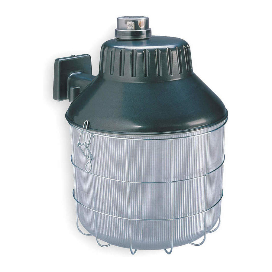
Housing
Cover
Lamp
Plate
2LBL5, 2LBL6
Photocontrol
Pin
Lag Screw
Mounting
(4)
Bracket
Gasket
Lens
598-1318-01
LPG-9272, LPG-9274
Advertisement

Summary of Contents for LumaPro 2LBL5
- Page 1 10. Install lamp. Lamp rating must match the rating of the fi xture. Model 2LBL5: 150 Watt high pressure sodium type S55 lamp. Model 2LBL6: 100 Watt metal halide type M90/O open rated lamp.
- Page 2 Impreso en la China 02/08 Modelo 2LBL5: Lámpara de seguridad de sodio de alta presión de 150 vatios Modelo 2LBL6: Lámpara de seguridad halógena metálica de 100 vatios 12. Afl oje en dos vueltas el tornillo que está en el centro del zócalo del fotocontrol.
- Page 3 Le fait de ne pas le faire pourrait entraîner de graves blessures ou des dommages. Conservez ces directives pour vous y référer, au besoin. Modèle 2LBL5 : Luminaire de sécurité à vapeur de sodium à haute pression de 150 W ®...
- Page 4 LIMITED LIFETIME WARRANTY: Should this product ever fail to perform satisfactorily due to a defect or poor workmanship, return it to the place of purchase and it will be replaced, free of charge. Incidental or consequential damages are excluded from this warranty. Light bulbs are not covered. GARANTÍA LIMITADA Y PERMANENTE: Si alguna vez este producto deja de funcionar satisfactoriamente debido a un defecto o defi...
Need help?
Do you have a question about the 2LBL5 and is the answer not in the manual?
Questions and answers