Table of Contents
Advertisement
Quick Links
Installation &
Operation Guide
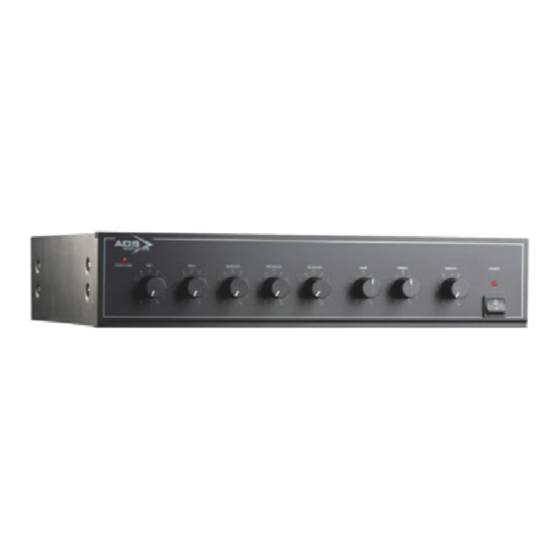
ADS 3120 Plus
120W ac/dc
Mixer Amplifier
PLEASE NOTE: THIS MANUAL AND THE NOTES CONTAINED HEREIN ARE COPYRIGHT AND
MAY NOT BE REPRODUCED EITHER WHOLLY OR IN PART, IN ANY WAY WHATSOEVER,
WITHOUT WRITTEN CONSENT OF ADSworldwide.
Audio Design Services Ltd, St David's House, Adcroft St, Higher Hillgate, Stockport, Cheshire SK1 3HW, UK.
TEL: +44 (0)161 666 6363
FAX: +44 (0)161 666 6366. WEB:
www.ads-worldwide.net
© 2008
Advertisement
Table of Contents

Related Manuals for ADS 3120 Plus


Summary of Contents for ADS 3120 Plus
- Page 1 Installation & Operation Guide ADS 3120 Plus 120W ac/dc Mixer Amplifier PLEASE NOTE: THIS MANUAL AND THE NOTES CONTAINED HEREIN ARE COPYRIGHT AND MAY NOT BE REPRODUCED EITHER WHOLLY OR IN PART, IN ANY WAY WHATSOEVER, WITHOUT WRITTEN CONSENT OF ADSworldwide.
- Page 2 Product Compliance to EC directives for Standard Products All standard products conform to the relevant directives, regulations and standards for electronic and associated apparatus. The equipment is CE marked both on the apparatus and the packaging. Our products meet the appropriate British and International standards. A product ‘Declaration of Conformity’...
- Page 3 IMPORTANT The lightning flash with arrowhead symbol, within an equilateral triangle, is intended to alert the user to the presence of un-insulated dangerous voltage within the product's enclosure that may be of sufficient magnitude to constitute a risk of electric shock to persons. The exclamation mark within an equilateral triangle is intended to alert the user to the presence of important operating and maintenance instructions in the literature accompanying the appliance.
-
Page 4: Table Of Contents
TABLE OF CONTENTS INTRODUCTION ....................5 Features ..........................5 Safety Information....................... 5 OPERATION ......................7 General Installation ......................7 Front Panel ......................... 7 Rear Panel .......................... 8 Priority Connections ......................8 MIC 1 and MIC 2 .......................... 8 Input Connections ....................... 9 MIC 1 and MIC 2 .......................... -
Page 5: Introduction
INTRODUCTION Features The ADS 3120 Plus is a 120 watt rms, two-zone, mixer amplifier suitable for powering medium to large sound systems where music may be required in one area and quiet in the rest of the building. Messages can be relayed to both areas using the priority switching system. - Page 6 If a 13-amp (BS1363) plug or other type of plug is used, a 5-amp fuse must be fitted either in the plug or at the distribution board. Green/Yellow Earth Brown Live Blue Neutral Fuse (max 5A) Fuse Holder IEC Mains Inlet Socket 13A Mains Plug Wiring (UK) For mains connection other than in the UK, refer to your local requirements for connection to the mains supply.
-
Page 7: Operation
Audio Design Services Ltd., St David’s House, Adcroft Street, Higher Hillgate, STOCKPORT SK1 3HW. OPERATION General Installation ALWAYS ensure that the equipment is properly earthed (grounded). Operating without an earth is dangerous and may cause high levels of audible hum from the speaker outputs. ... -
Page 8: Rear Panel
Rear Panel 15 16 17 18 19 20 21 22 MAINS SOCKET DC IN TERMINALS LOUDSPEAKER TERMINALS BOOSTER OUT (VARIABLE) BOOSTER OUT (FIXED OR VARIABLE) AUX 3 MIC 5 AUX 2 MIC 4 AUX 1 MIC 3 MIC 2 MIC 1 MIC 1 Priority Connection MIC 2 Priority Connection MIC 1 Trim Control... -
Page 9: Input Connections
5-pin DIN socket. Any of these connectors may be used. However if priority is required it may be easier to use the DIN socket and compatible ADS Signet microphone. (See Priority Connections 25 and 26 and wiring table on Page 8 for the DIN socket.) -
Page 10: Phantom Power
All inputs are configured as AUX inputs. To configure them as balanced microphone inputs proceed as follows disconnect the power supply then remove the amplifier top cover locate the correct switch on the rear PCB (MIC 4 is the centre one and MIC 5 the right hand one when viewed from the front of the amplifier) ... -
Page 11: Booster Output
Booster Output Variable Output Where a variable output is required this is available through the 5-pin DIN output socket (see Rear Panel No.16 on Page 8). The output is dependent on all controls. Function 5-pin DIN socket Variable output. Screen. Open collector to ground when a priority signal is present. -
Page 12: Accessories
Accessories 1 x Instruction Manual 1 x Mains Supply Lead 1 x 19-inch Rack Mounting Kit Some Possible Interfaces 100V line out to loudspeakers Booster Amplifier 24V battery CD Player Tuner Radio Mic Paging dc IN AUX3 AUX1 Receiver Microphones... -
Page 13: Troubleshooting
Audio Design Services Ltd., St David’s House, Adcroft Street, Higher Hillgate, STOCKPORT SK1 3HW. TROUBLESHOOTING Symptom Possible Cause Remedy No ac power Ensure that the supply cable is correctly connected to the mains outlet and the supply is turned on. Amplifier is off Switch on amplifier by pressing the on/off switch. -
Page 14: Specifications
Audio Design Services Ltd., St David’s House, Adcroft Street, Higher Hillgate, STOCKPORT SK1 3HW. SPECIFICATIONS Amplifier Output Power 120W rms into 8Ω at 1 kHz Constant Voltage Output 100V Distortion at Rated Power <2% THD Frequency Response 50Hz to 18kHz, -3dB Tone Control Range Bass: ±10db at 100Hz Treble: ±10db at 10kHz... -
Page 15: Notes
NOTES Reference Note Page 15 of 16... -
Page 16: Warranty Conditions
Audio Design Services Ltd T/A ADSworldwide St David’s House Adcroft Street Higher Hillgate STOCKPORT SK1 3HW 0161 666 6363 Telephone: 0161 666 6366 Fax: info@ads-worldwide.net Email: www.ads-worldwide.net Web: Page 16 of 16...
Need help?
Do you have a question about the 3120 Plus and is the answer not in the manual?
Questions and answers