Table of Contents
Advertisement
Quick Links
Advertisement
Table of Contents

Summary of Contents for alarco ATA
- Page 1 Axial Fan Unit Heaters Operation Manual...
- Page 2 Revision Date: 180806 Published on: 180806 Revision No: 2...
-
Page 3: Table Of Contents
Axial Fan Unit Heaters Operation Manual Contents Introduction ................5 Guarentee and Service ............6 General Characteristics ............7 Dimensions ................8 Other Technical Characteristics ..........8 Air Distribution Distances ..............9 Coil Water Pressure Drop Graphic ............9 Installation Rules ..............10 Location Selection and Mounting ............10 Water Pipes Installation .............. -
Page 4: Introduction
First of all, thanks for preferring ALARKO. This manual includes operation and maintenance information regarding ALARKO ATA axial fan unit heaters. Please, carefully read this manual for that you can operate your heater with high output, cheap, trouble free and long-term use. -
Page 5: Guarentee And Service
Guarantee and Service In the terms of obeying the instructions, warnings, points in this manual and the standards in charge (EN norms and directives must be applied if mentioned standards are not in use) heater is under 2 (two) years guarantee. Alarko Carrier is responsible for repairing or renewing if the following conditions are available. -
Page 6: General Characteristics
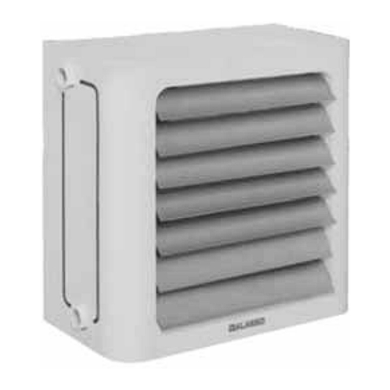
General Characteristics The objective of the apparatus is to heat the ambient air using water and vapor. The apparatus consists of three main parts; (Figure 1) 1. Coil 2. Fan 3. Air Directors Coil: Hot water or vapor circulates in the coil. It consists of aluminum or steel fins arranged on copper or steel pipe in order to increase the heat transfer surface. -
Page 7: Dimensions
Dimensions Dimensions Dimensions Boyutlar (mm) (mm) (mm) ATA 6 440 240 350 320 330 360 ATA 12 500 240 405 360 330 360 ATA 17 560 260 465 410 432 380 ATA 22 615 260 530 460 432 400 ATA 28... -
Page 8: Air Distribution Distances
Air Distribution Distances Air Flow Air Throw Üfleme Debisi Üfleme Uzakl›klar› Kademe /saat) (metre) /hour) Speed (meter) Yüksek High ATA 6 Orta Medium Düflük Yüksek 1800 High ATA 12 Orta 1400 Medium Düflük 1000 Yüksek 2600 High ATA 17 Orta... -
Page 9: Installation Rules
Installation Rules Location Selection and Mounting The heater should be mounted in a closed area where it shall not be exposed to outer effects like rain, frost. The fan section of the unit should be accessible. The wall-mounting or ceiling-mounting of the heater should be performed in different ways. -
Page 10: Water Pipes Installation
Please, find water pipe diameters we suggest in the Table 1. Is›t›c› Ak›flkan Ba¤lant›lar› Heating Liquid Connections S›cak ve K›zg›n Su Buhar Hot Water Steam (Diflli) (Diflli) (Flanfll›) (Diflli) (Threaded) (Threaded) (Flanged)(Threaded) ATA 6 1/2” 1/2” DN20 1/2” ATA 12 3/4” 3/4” DN25 1/2” ATA 17 3/4” 3/4”... - Page 11 Figure 4 and 5 illustrates various alternatives for connections. These illustrations are just suggestions; the installation should be made by qualified personnel. Hot water flow pipe SÕcak/kÕzgÕn su gidiú borusu Hot water return pipe SÕcak/kÕzgÕn su dönüú borusu Valve Vana Valve Vana Water Discharge...
- Page 12 Steam Pipe Buhar borusu Kondens borusu Condensation pipe Steam Valve Buhar VanasÕ Pislik Valve Filter Vana Tutucu Condenstop Kondenstop Figure 5A: Connection to steam installation. ùekil 5A: Buhar tesisatÕna ba÷lantÕ. The case when the heater is lower than the condensation pipe CihazÕn kondens borusundan aúa÷Õda oldu÷u durum Steam Valve Buhar VanasÕ...
-
Page 13: Electricity
Electricity: All electrical connections should be made by a qualified electrician. The fan motors of the heater operate with 220 V, 50 Hz power. Fan motors have their own thermal protections. Thus, there is no need to install thermal protection. The cables to fans should be min. -
Page 14: Trouble-Shooting Manual
There may be plastic bag, paper etc. stuck on the coil surface. See if the propeller is dirty or its balance is disordered. Product Ordering Notation ATA 36 D S S (for hot water and max. 2,5 atu steam, stan- dard copper pipe - aluminum fin) K (for red-hot water and max. - Page 15 web: www.alarko-carrier.com.tr e-posta: info@alarko-carrier.com.tr MDH: 444 0 128 İSTANBUL : GOSB - Gebze Org. San. Bölgesi, Ş. Bilgisu Cad. 41480 Gebze-KOCAELİ Tel: (0262) 648 60 00 - Fax: (0262) 648 60 08 ANKARA : Sedat Simavi Sok. No: 48, 06550 Çankaya - ANKARA Tel: (0312) 409 52 00 - Fax: (0312) 440 79 30 İZMİR : Şehit Fethibey Cad.
Need help?
Do you have a question about the ATA and is the answer not in the manual?
Questions and answers