Table of Contents
Advertisement
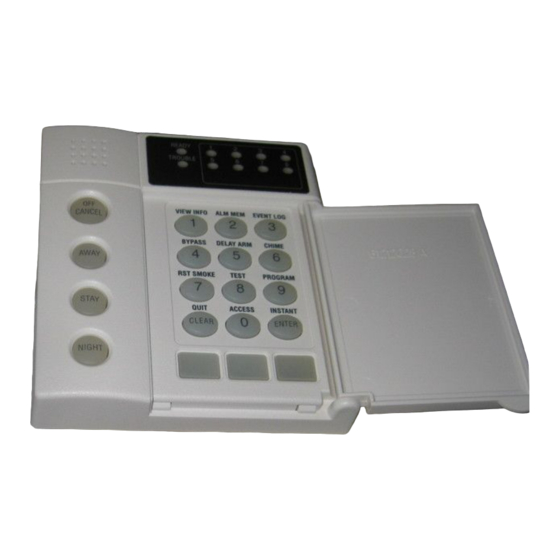
How to Use Your
Moose Security System
ZXLED8/ZXLED1 2
1
READY
TROUBLE
5
FIRE
9
VIEW INFO
ALM MEM
OFF
D
1
2
CANCEL
BYPASS
DELAY ARM
4
5
AWAY
RST SMOKE
TEST
7
8
QUIT
ACCESS
STAY
0
CLEAR
HOME
NIGHT
A
B
1
(ZXLED12 shown)
Control Station
2
3
4
6
7
8
10
11
12
EVENT LOG
3
CHIME
6
PROGRAM
9
INSTANT
ENTER
NEXT
C
PREV
Advertisement
Table of Contents

Related Manuals for MOOSE ZXLED12


Summary of Contents for MOOSE ZXLED12
- Page 1 How to Use Your Moose Security System ZXLED8/ZXLED1 2 Control Station READY TROUBLE FIRE VIEW INFO ALM MEM EVENT LOG CANCEL BYPASS DELAY ARM CHIME AWAY RST SMOKE TEST PROGRAM QUIT ACCESS INSTANT STAY CLEAR ENTER HOME NEXT NIGHT PREV (ZXLED12 shown)
- Page 2 INTRODUCTION Thank you for choosing the ZX200/ZX210 or ZX400/ZX410 Security Control. This control will provide you with years of reliable operation when properly installed and maintained. To maximize the benefits of your Security System, it is important to carefully read the entire contents of this manual and become familiar with all control operations.
-
Page 3: Table Of Contents
TABLE OF CONTENTS Table of Contents Operating Your System ..........5 The LED Control Station ..........5 The Control Station Keys ..........6 The Control Station Display ..........8 Turning Your System ON ..........9 Turning Your System OFF ..........9 Silencing Alarms ............ - Page 4 TABLE OF CONTENTS ZX200/ZX210 Programming ........25 Remote Connect ............25 Programming the User Passcodes ......... 25 ZX400/ZX410 Programming ........27 Remote Connect ............27 Set Clock ............... 28 Programming the Automatic-ON Feature ..... 29 Programming the Latch Key Feature ......33 Programming the User Passcodes .........
-
Page 5: Operating Your System
ACCESS INSTANT STAY CLEAR ENTER HOME NEXT NIGHT PREV ZXLED8 READY TROUBLE FIRE EVENT LOG VIEW INFO ALM MEM CANCEL BYPASS DELAY ARM CHIME AWAY RST SMOKE TEST PROGRAM QUIT ACCESS INSTANT STAY CLEAR ENTER HOME NEXT NIGHT PREV ZXLED12... -
Page 6: The Control Station Keys
OPERATING YOUR SYSTEM The Control Station Keys VIEW INFO KEY This key is used to view system information. ALARM MEMORY KEY Allows you to display the most recent zones where an alarm occurred. EVENT LOG KEY (ZX400/ZX410 only) If a printer is attached, you may print the recorded activi- ties. - Page 7 OPERATING YOUR SYSTEM ARMED STATUS INDICATOR These keys, followed by your passcode, are used to turn your system ON. Each key corresponds to a different level of security. No one at home; total protection; all sensors are ON. AWAY Building is occupied; selected door and window sensors are STAY Bedtime;...
-
Page 8: The Control Station Display
READY TROUBLE TROUBLE FIRE FIRE ZXLED8 ZXLED12 Ready Light Illuminates when the system is ready to be turned ON. If not illuminated, one or more zones have not been secured. See Operating Your System - System Not Ready. Trouble Light... -
Page 9: Turning Your System On
OPERATING YOUR SYSTEM Turning Your System ON 1. Close all doors and windows. 2. Check for a Ready light on the Control Station. If you do not see it, see Operating Your System - System Not Ready. 3. Press AWAY STAY NIGHT 4. -
Page 10: Silencing Alarms
OPERATING YOUR SYSTEM Silencing Alarms To silence an alarm: 1. Press CANCEL 2. Enter passcode: Silencing an alarm quickly may prevent a false alarm from being reported to the authorities. If the Armed Status Indicator light is NOT flashing, you can stop the false alarm from being reported. If the Armed Status Indicator light is flashing, then the false alarm has been reported and you need to contact the Central Station. -
Page 11: Chime
OPERATING YOUR SYSTEM 2 buttons will flash indicating exit countdown time. It is safe to exit the building during the exit countdown time. If you exit during the last 10 seconds of countdown time, the timer will restart the countdown once. If you turn your system ON in the AWAY mode and you do not exit, the countdown will begin again only once so that you may exit. -
Page 12: Optional Features
OPTIONAL FEATURES Optional Features Bypass - (DO NOT enable for UL Listed Systems) This feature allows you to turn your system ON with one or more zones intentionally left unprotected until the system is turned OFF. WARNING Bypassed zones are unprotected and will not cause an alarm if opened while your system is ON. -
Page 13: Selective Bypass/Unbypass
OPTIONAL FEATURES Selective Bypass/Unbypass - (to intentionally bypass/unbypass a specific zone) 1. Press 2. Enter passcode: 3. The Ready and Trouble LEDs will flash. 4. Enter the zone number: 5. Press ENTER Repeat steps 4 & 5 for each zone. See Protection Zones for a list of zone numbers and descriptions. -
Page 14: Force-Arming
OPTIONAL FEATURES Force-Arming - (DO NOT enable for UL Listed Systems) When you turn the system ON with Force-Arming, the system will not turn ON any zones that are not ready. Once the zone is secured, that zone is automatically turned ON and will cause an alarm if it is violated. The LED of a zone that is not ready will be lit. -
Page 15: Automatic-On
OPTIONAL FEATURES Automatic-ON - (DO NOT enable for UL Listed Systems) (ZX400/ZX410 only) This feature turns your system ON at a scheduled time daily. Your Control Station will sound an audible warning each minute starting at ten (10) minutes before the system turns ON. See ZX400/ZX410 Programming - Programming the Automatic-ON Feature and Cancel- ling Automatic-ON For Today. -
Page 16: Access Output
OPTIONAL FEATURES Access Output (This system is not UL Listed for Access Control) To activate an access output device or door strike: 1. Press 2. Enter passcode: Duress To send a silent alarm signal: 1. Press AWAY STAY NIGHT CANCEL 2. -
Page 17: User On Premise
OPTIONAL FEATURES User On Premise When a User On Premise passcode is used to activate in access output, disarm, or silence an alarm, notification will be reported to the Central Station or to a pager. See your Security Company Representative for more details. - Page 18 OPTIONAL FEATURES Below is the description of what your secondary functions keys are programmed to do: ENTER ENTER ENTER ENTER ENTER ENTER...
-
Page 19: Alarm Conditions
OPTIONAL FEATURES ALARM CONDITIONS Alarm Conditions Alarm Memory To view zones that went into alarm: 1. Press 2. Enter passcode: 3. All zones that went into alarm will light briefly and the Ready and Trouble LED will flash. -
Page 20: Trouble Conditions
TROUBLE CONDITIONS Trouble Conditions When your system detects a trouble condition, the LED Control Station lights the TROUBLE light. Silencing Trouble To silence the trouble sounder: 1. Press CANCEL 2. Enter passcode: Identifying Trouble Conditions After you silence the trouble sounder, the trouble light will remain ON. To view which zone(s) caused the zone condition, press the View Info key (Key #1). -
Page 21: Testing Your System
OPTIONAL FEATURES TESTING YOUR SYSTEM Testing Your System It is recommended that all tests be performed on a weekly basis. Your system must be OFF to perform these tests. There are six (6) options available. Walk Verifies that all system zones are operating properly Battery Verifies that the system battery is fully charged Bell... -
Page 22: Battery Test
TESTING YOUR SYSTEM Battery Test The battery test is used by the Security Company Representative to test the battery after a new battery has been installed. Your battery is automatically tested every 15 minutes. To perform a battery test: 1. Press 2. -
Page 23: Communicator Test
OPTIONAL FEATURES TESTING YOUR SYSTEM Communicator Test NOTE Your system must be monitored by a Central Station to perform this test. This test will take a while to perform. This test is used to verify that your system is communicating with the Central Station. -
Page 24: Rf Signal Strength
TESTING YOUR SYSTEM RF Signal Strength (ZX400/ZX410 only) If your system includes wireless sensors, then you can test the strength of signals from these sensors by performing an RF Signal Strength test. The strength of a signal can be affected by a low battery condition on the sensor or changes in the environment due furniture or appliances. -
Page 25: Zx200/Zx210 Programming
OPTIONAL FEATURES ZX200/ZX210 PROGRAMMING ZX200/ZX210 Programming Your system has several features which you may be able to program yourself. DO NOT attempt to program the system unless you have been properly trained on programming procedures and you fully understand these operations. There are two (2) options available: Remote Connect Allows the installer to program and diagnose problems from a remote site using the... - Page 26 ZX200/ZX210 PROGRAMMING 4. Enter the User Passcode ID (1 - 9) that you wish to program/change. 5. Press ENTER 6. Enter new four-digit passcode: Repeat steps 4 - 6 for each passcode to be programmed or press to return to the Ready mode. CLEAR If the new passcode being entered is a duplicate of an existing one, the Control Station will sound an error tone and return to the first digit...
-
Page 27: Zx400/Zx410 Programming
OPTIONAL FEATURES ZX400/ZX410 PROGRAMMING ZX400/ZX410 Programming Your system has several features which you may be able to program yourself. DO NOT attempt to program the system unless you have been properly trained on programming procedures and you fully understand these operations. There are seven (7) options available: Remote Connect Allows the installer to program and diagnose problems from a remote site using the... -
Page 28: Set Clock
ZX400/ZX410 PROGRAMMING Set Clock The clock is set according to military time (24:00 hours). To set the clock: 1. Press 2. Enter passcode: The Ready and Trouble LEDs will flash. 3. Press . Set the new time and date (see example). EXAMPLE: To set the clock to 2:15 pm on June 17, 1997: Press (2:15 pm) -
Page 29: Programming The Automatic-On Feature
OPTIONAL FEATURES ZX400/ZX410 PROGRAMMING Programming the Automatic-ON Feature (DO NOT enable for UL Listed Systems) This feature allows you to automatically turn your system ON at certain times for certain days. There are four items to be programmed: A. Setting the Security Level B. - Page 30 ZX400/ZX410 PROGRAMMING B. Day(s) To Turn ON To select the day(s) of the week you want your system to automatically turn ON, add together the values below for those days selected. Value Day of the Week Sunday Monday Tuesday Wednesday Thursday Friday Saturday...
- Page 31 OPTIONAL FEATURES ZX400/ZX410 PROGRAMMING C. Hour To Turn ON Each Day If the time scheduled is from 12:00 am to 12:09 am, the ten minute warning period will not begin until 12:00 am and will therefore be less than the set ten minute time period. The hour to turn ON must be entered, in military format, for each day you selected.
- Page 32 ZX400/ZX410 PROGRAMMING D. Minute To Turn ON Each Day The minute to turn ON must be entered for each day you selected. Each day has a corresponding location number. Location Day of the Week minute on Sunday minute on Monday minute on Tuesday minute on Wednesday minute on Thursday...
-
Page 33: Programming The Latch Key Feature
OPTIONAL FEATURES ZX400/ZX410 PROGRAMMING Programming the Latch Key Feature This feature allows you to monitor the entry of a designated person. The system will look for that user’s passcode to be used on the selected day(s) during the programmed time frame. During that time frame, the Control Station will chime once a minute until that person’s passcode is entered or the time frame has expired. - Page 34 ZX400/ZX410 PROGRAMMING B. Day(s) of Week to Monitor To select the day(s) of the week you want to be monitored, add together the values below for those days selected. Value Day of Week Sunday Monday Tuesday Wednesday Thursday Friday Saturday Example: To set up monitoring for Monday, Wednesday, and Friday, add 2 + 8 + 32.
- Page 35 OPTIONAL FEATURES ZX400/ZX410 PROGRAMMING C. Latch Key Time Window The latch key time window is the amount of time in minutes, before and after the scheduled time, that the selected user has to enter the designated passcode. The time frame may be from 0 minutes to 255 minutes.
- Page 36 ZX400/ZX410 PROGRAMMING D. Hour To Be Monitored For Each Day The monitoring hour must be entered, in military format, for each day you selected. Each day has a corresponding location number. Location Day of the Week hour on Sunday hour on Monday hour on Tuesday hour on Wednesday hour on Thursday...
- Page 37 OPTIONAL FEATURES ZX400/ZX410 PROGRAMMING E. Minute To Be Monitored For Each Day The monitoring minute must be entered for each day you selected. Each day has a corresponding location number. Location Day of the Week minute on Sunday minute on Monday minute on Tuesday minute on Wednesday minute on Thursday...
-
Page 38: Programming The User Passcodes
ZX400/ZX410 PROGRAMMING Programming the User Passcodes Your system may be programmed with up to 50 user passcodes. Consult your Security Company Representative as to which passcodes have been enabled and what Authority Level has been assigned to each one. To change a user passcode: 1. -
Page 39: Cancelling The Automatic-On For Today
OPTIONAL FEATURES ZX400/ZX410 PROGRAMMING Cancelling the Automatic-ON for Today If your system is programmed to perform an Automatic-ON scheduled for today, you may cancel it for today only without changing your programmed schedule. To cancel Automatic-ON for Today: 1. Press 2. -
Page 40: Multi-Area Operation
MULTI-AREA OPERATION Multi-Area Operation (ZX400/ZX410 only) Your system may be configured with two separate areas of protection. For example, a duplex may have one system but have both halves set up as separate areas for protection. Or, you may have one system for your house and a storage building with each building set up as sepa- rate areas for protection. -
Page 41: Fire Detection
OPTIONAL FEATURES FIRE DETECTION Fire Detection Introduction Your system may include fire detection, depending on the options purchased and the local codes and regulations for your area. Fire alarm systems are always active and cannot be turned OFF. All fire systems require regular testing and maintenance. -
Page 42: Developing An Evacuation Plan
FIRE DETECTION you have silenced a Fire Alarm, you will need to reset the smoke detector. Press the RESET SMOKE key (7) and enter your passcode. The trouble condition should disappear on the zone in a couple of seconds. If the trouble condition does not clear after resetting the smoke detector, contact your installer for service. -
Page 43: Fire Prevention And Escape
OPTIONAL FEATURES FIRE DETECTION Fire Prevention And Escape The purpose of heat and smoke detectors is to detect a fire in its earliest stages and sound an alarm, giving you more time to exit the premises before smoke reaches a dangerous level. Know Fire Hazards No detection device can protect life in all situations. -
Page 44: Be Prepared
FIRE DETECTION Be Prepared Perform fire drills regularly. Use them to assure recognition of an alarm signal. For your protection, simulate different circumstances (smoke the hall, living room, etc.). Then have everyone react to the situation. Draw a floor plan and show two exits from each room. It is important that children be instructed carefully. -
Page 45: Glossary
OPTIONAL FEATURES GLOSSARY Glossary Alarm Memory: A history of the alarms that occurred most recently. Bypass: To temporarily remove a zone from operation. Control Station: The remote station used to enter instructions to the control panel such as to arm, disarm and bypass. Also called a keypad. Entry Time: Time permitted to enter the armed premises through a delay defined zone. - Page 46 GLOSSARY Sensors: Devices that detect violations and report such conditions to the control panel. Sensors include door and window contacts or any device used to inform the control of a particular condition. Supervisory/Trouble: Your installer may have defined one or more of your control’s zones for supervisory/trouble condition indication.
-
Page 47: Index
OPTIONAL FEATURES INDEX Index Access Key 6 Instant Key 6 Access Output 6, 16, 17 Alarm Memory 6, 10, 19, 41, 45 Keypad Test 21, 23 Armed Status Indicator 7, 9, Keyswitch 15, 50 Authority Level 25, 38 Automatic-ON 6, 15, 27, Lamp Trigger 17 29, 39, 50 Latch Key 27, 33, 35, 45... - Page 48 INDEX Ready Light 8, 9 Unbypass 13 Remote Connect 25, 27 Universal Output 17 Reset Smoke Key 6, 42 User ID passcode 26, 33, 38 RF Signal Strength 21, 24 User On Premise 17, 50 Secondary Function Keys 17 View Info Key 6, 20 Security Level 10, 11, 29 Silence 6, 10, 15, 16, 17, 20, 41, 42...
-
Page 49: System Reference Guide
OPTIONAL FEATURES SYSTEM REFERENCE GUIDE System Reference Guide Emergency Numbers Police Fire Neighbor Doctor Central Station Service Rep. Central Station Subscriber Number Delay Times Seconds of exit delay time for AWAY arms Seconds of exit delay time for STAY and NIGHT arms Seconds of entry time (Delay 1) for Zone(s) Seconds of entry time (Delay 2) for Zone(s) Seconds of pre-alarm time... - Page 50 SYSTEM REFERENCE GUIDE Passcode Attempts Before Control Station Lockout: NOTE The lockout is a temporary measure that affects only the Control Station in use for the passcode attempts. Features Enabled Bypassing Exit-ON Hold Up Force-Arming Automatic-ON Auxiliary Alarm Double Press ON Keyswitch User On Premise Two Button ON...
-
Page 51: Protection Zones
OPTIONAL FEATURES PROTECTION ZONES Protection Zones One or more sensing devices have been assigned by the installer of your alarm system to each of the various protection zones in your system (although not every zone may have been used). For example, the sensing device on your Entry/Exit door may have been assigned to zone 01, sensing devices on windows in the master bedroom to zone 02, and so on. - Page 52 NOTES Notes...
- Page 53 NOTES Notes...
- Page 54 NOTES Notes...
- Page 55 NOTES Notes...
- Page 56 NOTES Notes...
- Page 57 NOTES Notes...
- Page 58 NOTES Notes...
-
Page 59: Owner's Insurance Premium Credit Requested
Owner’s Insurance Premium Credit Requested This form should be completed and forwarded to your homeowner’s insurance carrier for possible premium credit. This control is UL Listed for: UL Grade A Household Burglary UL Household Fire A. General Information: Insured’s Name and Address Insurance Co. - Page 60 E. Smoke Detector Locations Furnace Room Kitchen Bedrooms Attic Basement Living Room Dining Room Hall Other F. Burglary Detecting Device Locations: Front Door Basement door All Exterior Doors Rear Door 1st Floor windows All Windows Interior Locations Other All Accessible Openings, Including Skylights, Air Conditioners and Vents G.
-
Page 61: Fcc Compliance
FCC COMPLIANCE FCC Compliance Part 68 Notification This equipment complies with Part 68 of the Federal Communications Commissions (FCC) rules. All connections to the telephone net work must be made through standard telephone company plugs and jacks, RJ31-X or equivalent, in such a manner as to allow for easy and immediate disconnection of the equipment. - Page 62 OPTIONAL FEATURES FCC COMPLIANCE Canadian Notice The Canadian Department of Communications label identifies certified equipment. This certification means that the equipment meets certain telecommunications network protective, operational and safety requirements. The Department does not guarantee that the equipment will operate to the user’s satisfaction. Before installing this equipment, users should ensure that it is permissible to be connected to the facilities of the local telecommunications company.
- Page 64 Sentrol, Inc. reserves the right to change specifications M O O S E without notice. © 1997 Sentrol, Inc. a p r o d u c t o f s e n t r o l , i n c...
Need help?
Do you have a question about the ZXLED12 and is the answer not in the manual?
Questions and answers