DW 9000 SERIES Owner's Manual
Single bass drum pedal/double bass drum pedal
Hide thumbs
Also See for 9000 SERIES:
- User manual ,
- Owner's manual (2 pages) ,
- Quick start manual (2 pages)
Table of Contents
Advertisement
Quick Links
DW 9000 SERIES BASS DRUM PEDALS
Section 1: Drive System Adjustments
Note: For a more relaxed, "fl oating" pedal feel, replace the standard Double
Chain Drive with the optional Nylon Strap Drive (included).
1. Remove the chain assembly by loosening the Footboard Angle
Adjustment Screw on the top of Rotor (using the drumkey end of the
9000 3-Way key) and the connecting screw and nut at the front end of
the footboard (using a phillips-head screw driver and a wrench).
2. Attach the nylon strap to the footboard by aligning the end of the strap
that has a single hole with the screw hole in the footboard and then
replacing and tightening the connecting screw and nut.
3. Connect the three-hole end of the strap to the captive nut in the
adjustment channel on the Rotor using the drumkey screw (provided).
1.1: Torque
Your pedal is factory set to the most popular settings, including the standard eccentric
(Accelerator) torque position. However, the 9000 Drive can be adjusted to a variety of
torque positions. Choosing
an eccentric setting creates an
in-direct relationship between
the beater and footboard—
increasing the velocity of
the pedal by shortening the
length of the stroke— and is
recommended for situations
that require increased speed
and sensitivity. A more
Torque position adjustments from eccentric (far left) to concentric (far right).
concentric (Turbo) setting maintains a direct relationship between the sprocket and
the footboard to provide a solid, powerful, consistent feel and is suggested for general-
purpose playing situations. To adjust the torque to achieve your desired feel:
1. Locate the hex screw that holds the sliding bar on the underside of the rotor.
2. Using the long hex end of the 3-Way key, loosen the hex screw and slide the bar
forward or backward to change the shape of the cam.
3. Retighten the hex screw once the desired position is achieved.
1.2: Footboard Angle
To change the footboard height and angle, loosen the adjusting key screw on the top
of the Rotor and slide the chain or strap forward or backward to achieve the desired
footboard height. Then tighten the adjusting key screw. This adjustment can be used to
compensate for changes made by adjusting the torque or to independently modify the
footboard angle to a more comfortable position.
Section 2: Beater Ball Adjustments
2.1: Height
The length of the beater rod can be adjusted to achieve the desired feel and impact
position. Loosen the beater position screw and raise or lower the beater rod to the
desired position and then tighten the screw. Generally, the beater should hit the center of
the drum or an area 1-2 inches above the center.
2.2: Memory Lock
1. Place the beater memory lock loosely on the beater shaft and place the beater shaft
in a normal playing position in the beater hub.
2. Slide the memory lock down the shaft so that it fi ts into the notches on the beater
hub.
3. Adjust the beater to the desired playing position and tighten the drumkey screw
on the beater hub as well as the set screw on the memory lock with the small allen
wrench (provided). The beater ball should be positioned at a right angle to the memory
lock so that the beater can be reversed from the soft felt to the hard plastic side by
slightly raising the beater and rotating it 180 degrees.
2.3: Playing Surface
The 101 Two-Way Beater (standard) has both a curved, medium felt side for a rounder,
warmer attack and a fl at, hard plastic side for a sharper, brighter attack, much like wood
but lighter in weight.
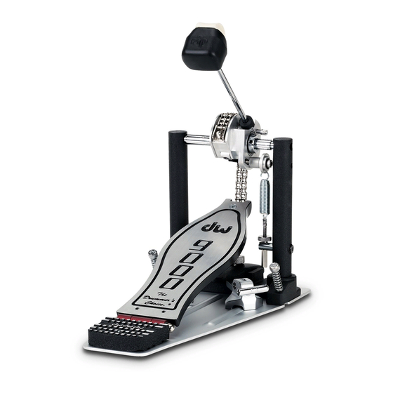
Remove the pedal, accessories and all packing materials from the box and/or case, then follow these instructions to set-up and adjust your pedal to fi t the way you play.
Two-Way Beater
Two-Way Beater
Floating Rotor
(Double Chain Drive)
(Double Chain Drive)
Footboard Angle
Footboard Angle
Adjustment Screw
Adjustment Screw
Floating Drive Shaft
Floating Drive Shaft
Infi nite Torque
Adjustment Screw
Adjustment Screw
Upright Post
Footboard
Stackable Heel
9000
9000
9002
Use the provided 3-Way key or any standard drum key to secure the linkage to the primary pedal
by tightening the key screw. Rotate the beater, casting and hex shaft on the auxiliary pedal to the
correct playing position, attach the linkage and tighten the auxiliary side key screw. Loosen the
two sets of key screws on the middle section of the linkage and adjust the length and angle of
the linkage to the desired position, then retighten the set screws. Set the linkage memory lock to
maintain the desired distance every time you set-up.
Elevator Heel Platform (U.S. Patent No. 6359205)
DW's advanced 9-Position "Elevator" Heel Plates provide
unique method for drummers to achieve a more comfortable pedal
playing position without sacrifi cing speed, power or accuracy. By using
different combinations of the heel sections, the height of the heel can
be adjusted independently of the angle of the footboard. The "Eleva-
tor" positions range from normal (#1) and slightly elevated (#2-3) to
raised (#4-7) and extreme (#8-9). Position #8, for example, is recom-
mended for achieving a smoother, more effortless heel-toe sliding
technique, while positions #2 and #3 offer a subtle but effective way to
increase control.
To install the Elevator heel sections, fi rst turn the pedal over and
remove the three screws holding the original heel (A) to the pedal
plate. In order to loosen chemical lock holding the three screws, you
may fi rst need to heat them with a hair dryer for 2-3 minutes. Place additional Elevator heel sections (B, C) either
Beater Shaft
Beater Memory Lock
Beater Position Screw
Delta Plus
Rocker/Stroke
Adjustment
Spring
Hoop Clamp
Height Adjustment
Spring Tension
Adjustment
Knurled Nut
Hex Nut
Spur
Hoop Clamp Adjustment
Hoop Clamp Adjustment
T-Screw
T-Screw
Pedal Plate
Delta Hinge
Double Pedal Linkage
Auxiliary Pedal
Primary Pedal
Double Pedal Linkage Adjustment
Double Pedal Linkage Adjustment
Customizing Your Pedal with the DW Bass Drum Pedal Stacking Heel Kit (part #1236 sold separately)
1
2
4
5
7
8
2.4: Weight (optional)
The adjustable beater weight can be positioned on the beater shaft to increase the power
of the stroke. Experiment to fi nd the optimum feel and secure the weight using the
standard drum key set screw.
Section 3: Slotted Stroke Adjustment
To modify the distance the beater travels during the course of each stroke:
1. Hold the beater ball with one hand and align the hex head of the stroke adjustment
screw with the access hole in the right upright post.
2. Using the other hand, place the long hex of the 3-way drum key through the hole in
the upright post and into the beater adjusting screw.
3. Loosen the screw and move the beater ball to the desired position while keeping the
key in the screw, then retighten, remove key and release.
Section 4: Spring Tension Adjustment
DW Drum Pedal Springs feature an internal noise reduction damper as well as a tension
locking mechanism. To increase or decrease the spring tension:
1. Loosen the round knurled nut at the base of the spring assembly.
2. Push down on the spring to release the self-locking hex nut.
3. Tighten or loosen the lock nut to the create the desired tension, then release the hex
nut and retighten knurled nut to lock-in the adjustment.
Section 5: Hoop Clamp Adjustments
The DW Hoop Clamp is designed to fi t a wide variety of manufacturer's bass drum
hoops. To set the space of the hoop clamp for your bass drum:
1. Use the allen wrench (provided) to loosen the set screw on the knurled nut.
2. Rotate the knurled nut to narrow or widen the gap and re-tighten the set screw.
3. Position the pedal on the center of the hoop and tighten the T-screw securely.
Use the provided rubber hoop protector to avoid damage to your bass drum hoop.
Section 6: Toe Stop, Non-Skid Spurs and Velcro™
To install the optional toe stop:
1. Remove the screw and nut at the front end of the footboard using a phillips-head
screw driver and a wrench.
2. Align the hole in the toe stop with the hole in the footboard and replace and tighten
the connecting screw and nut.
All DW Bass Drum Pedals include built-in adjustable spurs and non-skid Velcro™ on
the bottom of the pedal plates to prevent bass drum crawl. The Velcro™ automatically
grips on most types of carpeting. To adjust the spurs, simply turn the knurled portion
clockwise for more skid control or counter-clockwise for less. Be careful when you use
the spurs as they may damage the fl oor.
Note: Some of the screws on the pedal have been treated with a chemical lock to prevent
unwanted loosening during playing. In order to loosen the chemical lock holding these screws,
you may fi rst need to heat them with a hair dryer for 2-3 minutes.
below or above the original section and re-attach the stacked heel sections using the longer screws (provided). The
a
a a
following chart indicates which screws (supplied) should be used in conjunction with the Elevator heel sections to
3
modify the height of your heel.
heel positionheel sections
heel position
#1
6
#2
A
#3
#4
B
#5
9
#6
C
#7
#8
#9
top screws
top screws
bottom screws
A
3/4"
-
A/B
3/4"
-
B/A
7/16"
7/16"
A/C
-
1 1/4"
A/C
3/4"
7/16"
A/C/B
3/4"
3/4"
B/A/C
7/16"
1 1/4"
C/B/A
-
1 1/2"
C/B/A
1 1/4"
7/16"
Advertisement
Table of Contents

Subscribe to Our Youtube Channel
Related Manuals for DW 9000 SERIES


Summary of Contents for DW 9000 SERIES
- Page 1 Upright Post Spring DW Drum Pedal Springs feature an internal noise reduction damper as well as a tension (Accelerator) torque position. However, the 9000 Drive can be adjusted to a variety of locking mechanism. To increase or decrease the spring tension: Hoop Clamp torque positions.
- Page 2 DW 9000 SERIES BASS DRUM PEDAL ACCESSORIES Pedal Pedal Drum Drum Bass Bass Double Double 9002 9002 SM101 Two-Way Bass Drum Beater Two-Way Bass Drum Beater Pedal Drum Bass Single 9000 SM102 Large Felt Bass Drum Beater Large Felt Bass Drum Beater...
Need help?
Do you have a question about the 9000 SERIES and is the answer not in the manual?
Questions and answers