Table of Contents
Advertisement
Quick Links
Advertisement
Table of Contents

Subscribe to Our Youtube Channel
Related Manuals for Supero X7DVL-3


Summary of Contents for Supero X7DVL-3
- Page 1 UPER X7DVL-3 X7DVL-i USER’S MANUAL Revision 1.0c...
- Page 2 The information in this User’s Manual has been carefully reviewed and is believed to be accurate. The vendor assumes no responsibility for any inaccuracies that may be contained in this document, makes no commitment to update or to keep current the information in this manual, or to notify any person or organization of the updates.
-
Page 3: About This Manual
Technology (EM64T). These features allow the motherboard to operate at much higher speeds with better power management in much safer thermal environ- ments than the traditional motherboards. The X7DVL-3/X7DVL-i is ideal for high performance dual processor (DP) and enterprise server environments. Please refer to the motherboard specifi... -
Page 4: Table Of Contents
Conventions Used in the Manual .................. iii Chapter 1: Introduction Overview ......................1-1 Checklist ....................1-1 Contacting Super Micro ................1-2 X7DVL-3/i Image ............... 1-3 X7DVL-3/i Layout ..............1-4 Quick Reference ..................1-5 Motherboard Features ................1-6 Intel 5000V (Blackford-VS) Chipset: System Block Diagram ....1-8 Chipset Overview ................... - Page 5 Table of Contents Power Button ..................2-13 2-5 Connecting Cables ..................2-14 ATX Power Connector ................2-14 Processor Power Connector ..............2-14 Universal Serial Bus (USB) ..............2-15 Chassis Intrusion ..................2-15 Fan Headers ..................2-16 Power Force-On ..................2-16 ATX PS/2 Keyboard and Mouse Ports .............
- Page 6 X7DVL-3/X7DVL-i User's Manual Chapter 3: Troubleshooting Troubleshooting Procedures ................3-1 Before Power On ..................3-1 No Power ....................3-1 No Video ....................3-1 Losing the System’s Setup Confi guration ..........3-1 Memory Errors ................... 3-2 Technical Support Procedures ............... 3-2 Frequently Asked Questions ................
-
Page 7: Chapter 1: Introduction
One (1) I/O backpanel shield (CSE-PT07L) One (1) CPU Retention Module (SKT-0159-for retail and bulk packaging) One (1) Super Micro CD containing drivers and utilities One (1) User's/BIOS Manual Optional (For SAS HostRAID 5) One (1) I-Button (to be purchased from Super Micro) (*X7DVL-3) -
Page 8: Contacting Super Micro
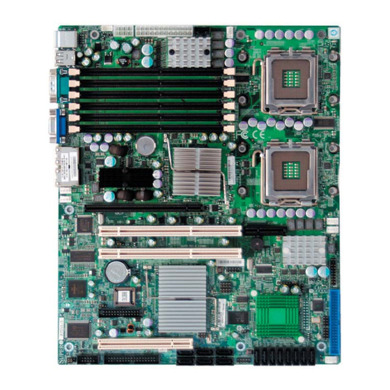
X7DVL-3/X7DVL-i User's Manual Contacting Super Micro Headquarters Address: Super Micro Computer, Inc. 980 Rock Ave. San Jose, CA 95131 U.S.A. Tel: +1 (408) 503-8000 Fax: +1 (408) 503-8008 Email: marketing@supermicro.com (General Information) support@supermicro.com (Technical Support) Web Site: www.supermicro.com Europe Address: Super Micro Computer B.V. - Page 9 Chapter 1: Introduction Figure 1-1. X7DVL-3/X7DVL-i Image *Note: The drawings and pictures shown in this manual were based on the latest PCB Revision available at the time of publishing of the manual. The motherboard you’ve received may or may not look exactly the same as the...
- Page 10 SAS are available on the X7DVL-3 only. SAS Connectors, the LSI SAS HostRAID Controller, the I-Button socket and 3-GSPIO0/3-GSPIO1 LEDs are built in on the X7DVL-3 only. I-Button is used to enable RAID 5. However, RAID 0, 1 and 10 are enabled through the LSI SAS Controller. (*I-Button is optional.)
-
Page 11: Quick Reference
PWR SMB (JPI Power System Management (I C) Header PWR Supply Fail (JPWF) Power Supply Failure (See Chapter 2) SAS0-SAS7 Serial Attached SCSI Connectors (#0-#7) (*X7DVL-3) SATA0-SATA5 (JS1-JS6) Intel SATA 0-5 Connectors SIMLP (J16) IPMI SIMM Low-profi le Slot T-SGPIO#0/1... -
Page 12: Motherboard Features
• Thermal Monitor 2 (TM2) support • CPU slow-down on temperature overheat • CPU thermal trip support for processor protection • Power-up mode control for recovery from AC power loss • Chassis intrusion detection • System resource alert via Supero Doctor III... - Page 13 Chapter 1: Introduction ACPI Features • Slow blinking LED for suspend state indicator • Main switch override mechanism • ACPI Power Management • Power-on mode for power recovery Onboard I/O • Six SATA ports (supporting RAID0, 1,10 and 5) • Six SAS ports (supporting RAID0, 1,10 and 5.) (*See Note 5 on Page 1-4) •...
- Page 14 X7DVL-3/X7DVL-i User's Manual PROCESSOR#2 PROCESSOR#1 ISL6306 ISL6306 667/1067/1333 667/1067/1333 MT/S MT/S FBD CHNL0 PORT #4,5 FBD CHNL1 PORT #6,7 PORT PORT #2,3 ATA 100 PORT PORT IDE CONN PCI-EXP X8 PORT #1,2 PCI-EX4 PORT 3.0Gb/S 1068E 3.0 Gb/S ESB2 PCI-X133MHz PCI 32/33MMZ USB 2.0...
-
Page 15: Chipset Overview
Chipset Overview Built upon the functionality and the capability of the 5000V (Blackford-VS) chipset, the X7DVL-3/X7DVL-i motherboard provides the performance and feature set required for dual processor-based servers with confi guration options optimized for communications, presentation, storage, computation or database applications. The 5000V (Blackford-VS) chipset supports a single or dual Intel Xeon 64-bit Quad Core/Dual Core processor(s) with front side bus speeds of up to 1.333 GHz. -
Page 16: Special Features
Advanced BIOS Setup section to change this setting. The default setting is Last State. PC Health Monitoring This section describes the PC health monitoring features of the X7DVL-3/X7DVL- i. All have an onboard System Hardware Monitor chip that supports PC health monitoring. -
Page 17: 1-5 Acpi Features
You can also confi gure Supero Doctor to provide you with warnings when the system temperature goes beyond a pre-defi... -
Page 18: Power Supply
It is even more important for processors that have high CPU clock rates. The X7DVL-3/X7DVL-i can only accommodate 24-pin ATX power supply. Although most power supplies generally meet the specifi cations required by the motherboard, some are inadequate. You should use one that will supply at least 400W of power. - Page 19 Chapter 1: Introduction tor, drive interface control logic and interrupt and DMA logic. The wide range of functions integrated onto the Super I/O greatly reduces the number of components required for interfacing with fl oppy disk drives. The Super I/O supports 360 K, 720 K, 1.2 M, 1.44 M or 2.88 M disk drives and data transfer rates of 250 Kb/s, 500 Kb/s or 1 Mb/s.
- Page 20 X7DVL-3/X7DVL-i User's Manual Notes 1-14...
-
Page 21: Chapter 2: Installation
Chapter 2: Installation Chapter 2 Installation Static-Sensitive Devices Electric-Static-Discharge (ESD) can damage electronic com ponents. To prevent damage to your system board, it is important to handle it very carefully. The following measures are generally suffi cient to protect your equipment from ESD. Precautions •... -
Page 22: Processor And Heatsink Fan Installation
X7DVL-3/X7DVL-i User's Manual Processor and Heatsink Fan Installation When handling the processor package, avoid placing direct pressure on the label area of the fan. *Notes: 1. Always connect the power cord last and always remove it before adding, removing or changing any hardware components. Make sure that you install the processor into the CPU socket before you install the CPU heatsink. - Page 23 Chapter 2: Installation North Center Edge 3. Use your thumb and your index fi nger to hold the CPU at the North Center Edge and the South Center Edge of the CPU. 4. Align CPU Pin1 (the CPU corner marked with a triangle) against the socket corner that is marked with a South Center Edge triangle cutout.
- Page 24 X7DVL-3/X7DVL-i User's Manual Installation of the Heatsink CEK Heatsink Installation CEK Passive Heatsink 1. Do not apply any thermal grease to the heatsink or the CPU die; the required amount has already been applied. 2. Place the heatsink on top of the CPU so that the four mounting holes are aligned with those on the retention mechanism.
- Page 25 Chapter 2: Installation 1. Unscrew and remove the heatsink screws from the motherboard in the sequence as shown in the picture on the right. 2. Hold the heatsink as shown in the picture on the right and gently wriggle the heatsink to loosen it from the CPU.
-
Page 26: Installing Dimms
Repeat for all modules (see step 1 above). Memory Support The X7DVL-3/X7DVL-i supports up to 16 GB fully buffered (FBD) ECC DDR2 533/667 in 6 DIMMs. Populating DIMM modules with pairs of memory modules of the same size and same type will result in Interleaved Memory which will increase memory performance. - Page 27 Chapter 2: Installation *Note 2: Due to memory allocation to system devices, memory remaining avail- able for operational use will be reduced when 4 GB of RAM is used. The reduction in memory availability is disproportional. (Refer to the following Memory Availability Table for details.
-
Page 28: Back Panel Connectors/Io Ports
X7DVL-3/X7DVL-i User's Manual Control Panel Connectors/IO Ports The I/O ports are color coded in conformance with the PC 99 specifi cation. See Figure 2-3 below for the colors and locations of the various I/O ports. A. Back Panel Connectors/IO Ports Figure 2-3. -
Page 29: Front Control Panel
Chapter 2: Installation B. Front Control Panel JF1 contains header pins for various buttons and indicators that are normally located on a control panel at the front of the chassis. These connectors are de- signed specifi cally for use with Super Micro server chassis. See Figure 2-4 for the descriptions of the various control panel buttons and LED indicators. -
Page 30: Front Control Panel Pin Defi Nitions
X7DVL-3/X7DVL-i User's Manual C. Front Control Panel Pin Defi nitions NMI Button NMI Button Pin Defi nitions (JF1) The non-maskable interrupt button Pin# Defi nition header is located on pins 19 and 20 Control of JF1. Refer to the table on the right Ground for pin defi... -
Page 31: Hdd Led
Chapter 2: Installation HDD LED HDD LED Pin Defi nitions (JF1) The HDD LED connection is located Pin# Defi nition on pins 13 and 14 of JF1. Attach a hard drive LED cable here to display HD Active disk activity (for any hard drives on the system, including SAS, Serial ATA and IDE). -
Page 32: Overheat/Fan Fail Led
X7DVL-3/X7DVL-i User's Manual Overheat/Fan Fail LED (OH) OH/Fan Fail LED Pin Defi nitions (JF1) Connect an LED to the OH/Fan Fail Pin# Defi nition connection on pins 7 and 8 of JF1 to provide advanced warning of chassis Ground overheating or fan failure. Refer to OH/Fan Fail Indicator the table on the right for pin defi... -
Page 33: Reset Button
Chapter 2: Installation Reset Button The Reset Button connection is located Reset Button on pins 3 and 4 of JF1. Attach it to the Pin Defi nitions (JF1) hardware reset switch on the computer Pin# Defi nition case. Refer to the table on the right for Reset pin defi... -
Page 34: Connecting Cables
X7DVL-3/X7DVL-i User's Manual Connecting Cables ATX Power 24-pin Connector Pin Defi nitions Pin# Defi nition Pin # Defi nition ATX Power Connector +3.3V +3.3V There are a 24-pin main power supply -12V +3.3V connector(JPW1) and an 8-pin CPU PWR connector (JPW3) on the moth- PS_ON erboard. -
Page 35: Universal Serial Bus (Usb)
Chapter 2: Installation Back Panel USB Universal Serial Bus (USB) (USB0/1) Pin# Defi nitions There are six USB 2.0 (Universal Serial Bus) ports/headers on the motherboard. Two of them are Back Panel USB ports (USB#0/1:J20), and Ground the other four are Front Panel USB headers (JUSB1: USB#2/3 JUSB2 USB#4/#5). -
Page 36: Fan Headers
X7DVL-3/X7DVL-i User's Manual Fan Headers Fan Header Pin Defi nitions (Fan1-6) The X7DVL-3/X7DVL-i has four chassis/sys- Pin# Defi nition tem fan headers (Fan3 to Fan6) and two CPU Ground Fans (Fans 1/2).(*Note: all these fans are 4-pin +12V fans. However, Pins 1-3 of the fan headers... -
Page 37: Atx Ps/2 Keyboard And Mouse Ports
Chapter 2: Installation ATX PS/2 Keyboard and PS/2 Keyboard and Mouse Port Pin PS/2 Mouse Ports Defi nitions The ATX PS/2 keyboard and the PS/2 Pin# Defi nition mouse are located at JKM1. See the Data table on the right for pin defi nitions. (The mouse port is above the key- Ground board port. -
Page 38: Wake-On-Ring
X7DVL-3/X7DVL-i User's Manual Wake-On-Ring Wake-On-Ring The Wake-On-Ring header is des- Pin Defi nitions (JWOR) ignated JWOR. This function allows Pin# Defi nition your computer to receive and be Ground awakened by an incoming call to the Wake-up modem when the system is in the suspend state. -
Page 39: Glan 1/2 (Ethernet) Ports
Chapter 2: Installation GLAN 1/2 (Giga-bit Ethernet GLAN1 Ports) Two G-bit Ethernet ports are desig- nated JLAN1 and JLAN2 on the I/O GLAN2 backplane. This port accepts RJ45 type cables. Power LED/Speaker Speaker Connector On the JD1 header, pins 1-3 are for a power LED and pins 4-7 are for the Pin Setting Defi... -
Page 40: Alarm Reset
X7DVL-3/X7DVL-i User's Manual Alarm Reset Alarm Reset If three power supplies are installed Pin Setting Defi nition and Alarm Reset (JAR) is enabled, the Pin 1 Ground system will notify you when any of the Pin 2 three power modules fails. Connect... -
Page 41: Power Smb Connector
SAS* connections. See the table on *Note: NC= No Connections the right for pin defi nitions. Refer to the board layout below for the locations of the headers. (*3-SGPIO0/1: X7DVL-3 Only.) JPWF A. PWR SMB B. T-SGPIO#0 C. T-SGPIO#1 D. 3-SGPIO#0 E. -
Page 42: Jumper Settings
X7DVL-3/X7DVL-i User's Manual Jumper Settings Explanation of Jumpers Connector Pins To modify the operation of the motherboard, jumpers can be used to choose between optional settings. Jumpers create shorts Jumper between two pins to change the function of the connector. Pin 1 is identifi ed with... -
Page 43: Cmos Clear
Chapter 2: Installation CMOS Clear JBT1 is used to clear CMOS. Instead of pins, this "jumper" consists of contact pads to prevent the accidental clearing of CMOS. To clear CMOS, use a metal object such as a small screwdriver to touch both pads at the same time to short the connection. -
Page 44: Vga Enable/Disable
X7DVL-3/X7DVL-i User's Manual VGA Enable/Disable VGA Enable/Disable Jumper Settings JPG1 allows you to enable or disable the Both Jumpers Defi nition VGA port. The default position is on pins Pins 1-2 Enabled (*Default) 1 and 2 to enable VGA. See the table... -
Page 45: Pwr Supply Failure
Chapter 2: Installation PWR Supply Failure/PWR PWR Supply PWR Fault Jumper Settings Fault Detect (JPWF) Jumper Setting Defi nition The system can notify you in the event Closed Enabled of a power supply failure. This feature is Open Disabled (*Default) available when three power supply units are installed in the chassis with one act- ing as a backup. -
Page 46: Software Raid Enable
X7DVL-3/X7DVL-i User's Manual Software RAID Enable Software RAID Jumper Settings JPA2 allows you to enable or disable the Jumper Settings Defi nition function of Software RAID. Close pins 1 Pins 1-2 (*Default) Software RAID Enabled & 2 to enable Software RAID (*Default). -
Page 47: Onboard Indicators
Chapter 2: Installation Activity L i n k Onboard Indicators GLAN LEDs Rear View (when viewing from the back of the chassis.) There are two GLAN ports on the moth- GLAN Activity Indicator erboard. Each Gigabit Ethernet LAN port has two LEDs. The yellow LED indicates Color Status Defi... -
Page 48: Post Code Led Indicators
X7DVL-3/X7DVL-i User's Manual POST Code LED Indicators (LE4, LE5) POST Code LED Indicators There are two POST Code LED Indicators POST Code Message (LE4, LE5) located on the motherboard. Yellow: On Green: Off Memory Initialization @ POST 28h These two LEDs indicate POST (Power... -
Page 49: Status Led
Chapter 2: Installation Status LED (D31) Status LED Indicator There is a Status LED Indicator (D31) LED Color Defi nition located on the motherboard. This LED Green Power On, system: normal displays different colors to show the status PWR on, PWR problem(s) of the system. -
Page 50: Parallel Port, Floppy, Simlp Ipmi And Hard Disk Drive Connections
X7DVL-3/X7DVL-i User's Manual Parallel Port, Floppy Drive, SIMLP IPMI and Hard Disk Drive Connections Note the following when connecting the fl oppy and hard disk drive cables: • The fl oppy disk drive cable has seven twisted wires. • A red mark on a wire typically designates the location of pin 1. -
Page 51: Floppy Connector
Chapter 2: Installation Floppy Connector Floppy Drive Connector Pin Defi nitions (Floppy) The fl oppy connector is located at Pin# Defi nition Pin # Defi nition J22. See the table below for pin Ground FDHDIN defi nitions. Ground Reserved FDEDIN Ground Index Ground... -
Page 52: Ide Connectors
X7DVL-3/X7DVL-i User's Manual IDE Connector IDE Drive Connectors Pin Defi nitions There is one IDE Connector (JIDE1) on Pin# Defi nition Pin # Defi nition the motherboard. The IDE Connector is Reset IDE Ground located next to the Front Panel Control... -
Page 53: Chapter 3: Troubleshooting
Chapter 3: Troubleshooting Chapter 3 Troubleshooting Troubleshooting Procedures Use the following procedures to troubleshoot your system. If you have followed all of the procedures below and still need assistance, refer to the ‘Technical Support Procedures’ and/or ‘Returning Merchandise for Service’ section(s) in this chapter. Note: Always disconnect the power cord before adding, changing or installing any hardware components. -
Page 54: Losing The System's Setup Confi Guration
X7DVL-3/X7DVL-i User's Manual Losing the System’s Setup Confi guration 1. Make sure that you are using a high quality power supply. A poor quality power supply may cause the system to lose the CMOS setup information. Refer to Section 1-6 for details on recommended power supplies. -
Page 55: Frequently Asked Questions
Question: What are the various types of memory that my motherboard can support? Answer: The X7DVL-3/X7DVL-i has six 240-pin DIMM slots that support DDR2 FBD ECC 533/667 SDRAM modules. It is strongly recommended that you do not mix memory modules of different speeds and sizes. (See Chapter 2 for detailed Information.) -
Page 56: Returning Merchandise For Service
X7DVL-3/X7DVL-i User's Manual Returning Merchandise for Service A receipt or copy of your invoice marked with the date of purchase is required be- fore any warranty service will be rendered. You can obtain service by calling your vendor for a Returned Merchandise Authorization (RMA) number. When returning to the manufacturer, the RMA number should be prominently displayed on the outside of the shipping carton, and mailed prepaid or hand-carried. -
Page 57: Chapter 4: Bios
Chapter 4 BIOS 4-1 Introduction This chapter describes the Phoenix BIOS™ Setup utility for the X7DVL-3/X7DVL-i. The Phoenix ROM BIOS is stored in a fl ash chip and can be easily upgraded using a fl oppy disk-based program. Note: Due to periodic changes to the BIOS, some settings may have been added or deleted and might not yet be recorded in this manual. -
Page 58: Running Setup
X7DVL-3/X7DVL-i User's Manual Running Setup *Default settings are in bold text unless otherwise noted. The BIOS setup options described in this section are selected by choosing the ap- propriate text from the main BIOS Setup screen. All displayed text is described in this section, although the screen display is often all you need to understand how to set the options (see the next page). -
Page 59: Main Bios Setup Menu
Chapter 4: BIOS Main BIOS Setup Menu Main Setup Features System Time To set the system date and time, key in the correct information in the appropriate fi elds. Then press the <Enter> key to save the data. System Date Using the arrow keys, highlight the month, day and year fi... - Page 60 X7DVL-3/X7DVL-i User's Manual IDE Channel 0 Master/Slave, IDE Channel 1 Master/Slave, SATA Port2 and SATA Port3 These settings allow the user to set the parameters of IDE Channel 0 Master/ Slave, IDE Channel 1 Master/Slave, IDE Channel 2 Master, IDE Channel 3 Master slots.
- Page 61 Chapter 4: BIOS CHS Format The following items will be displayed by the BIOS: TYPE: This item displays the type of IDE or SATA Device. Cylinders: This item indicates the status of Cylinders. Headers: This item indicates the number of headers. Sectors: This item displays the number of sectors.
- Page 62 X7DVL-3/X7DVL-i User's Manual Parallel ATA This setting allows the user to enable or disable the function of the Parallel ATA. The options are Disabled and Enabled. Serial ATA This setting allows the user to enable or disable the function of the Serial ATA. The options are Disabled and Enabled.
-
Page 63: Advanced Setup
Chapter 4: BIOS System Memory This display informs you how much system memory is recognized as being present in the system. Extended Memory This display informs you how much extended memory is recognized as being present in the system. Advanced Setup Choose Advanced from the Phoenix BIOS Setup Utility main menu with the arrow keys. - Page 64 X7DVL-3/X7DVL-i User's Manual Boot Features Access the submenu to make changes to the following settings. QuickBoot Mode If enabled, this feature will speed up the POST (Power On Self Test) routine by skipping certain tests after the computer is turned on. The settings are Enabled and Disabled.
- Page 65 Chapter 4: BIOS Memory Cache Cache System BIOS Area This setting allows you to designate a reserve area in the system memory to be used as a System BIOS buffer to allow the BIOS to write (cache) data into this reserved memory area.
- Page 66 X7DVL-3/X7DVL-i User's Manual to be cached into the buffer and written into the system memory at the same time. Select Write Protect to prevent data from being written into the extended memory area above 1MB. Select Write Back to allow the CPU to write data back directly from the buffer without writing data to the System Memory for fast CPU data processing and operation.
- Page 67 Chapter 4: BIOS Slot1 PCI 33MHz, Slot5 PCI-X 133MHz, Slot6 PCI-X 133MHz, Slot6 <Ext> PCI-Exp. x8 Access the submenu for each of the settings above to make changes to the following: Option ROM Scan When enabled, this setting will initialize the device expansion ROM. The options are Enabled and Disabled.
- Page 68 X7DVL-3/X7DVL-i User's Manual Branch 0 Rank Interleaving Select enable to enable the functions of Memory Interleaving for Branch 0 Rank. The options for Memory Interleaving are 1:1, 2:1 and 4:1. Branch 0 Rank Sparing Select enable to enable the sparing feature for Branch 0 Rank. The options are Enabled and Disabled.
- Page 69 Chapter 4: BIOS Route Port 80h Cycles to This feature allows the user to decide which bus to send debug information to. The options are Disabled, PCI and LPC. Clock Spectrum Feature If Enabled, the BIOS will monitor the level of Electromagnetic Interference caused by the components and will attempt to decrease the interference whenever needed.
- Page 70 X7DVL-3/X7DVL-i User's Manual Thermal Management 2 (*Available when supported by the CPU.) Set to Enabled to use Thermal Management 2 (TM2) which will lower CPU voltage and frequency when the CPU temperature reaches a predefi ned overheat threshold. Set to Disabled to use Thermal Manager 1 (TM1), allowing CPU clocking to be regulated via CPU Internal Clock modulation when the CPU temperature reaches the overheat threshold.
- Page 71 Chapter 4: BIOS Intel <R> Virtualization Technology (*Available when supported by the CPU.) Select Enabled to use the feature of Virtualization Technology to allow one platform to run multiple operating systems and applications in independent partitions, creating multiple "virtual" systems in one physical computer. The options are Enabled and Disabled.
- Page 72 X7DVL-3/X7DVL-i User's Manual Interrupt This setting allows you to select the IRQ (interrupt request) for serial port B. The options are IRQ3 and IRQ4. Parallel Port This setting allows you to assign control of the parallel port. The options are Enabled (user defi...
- Page 73 Chapter 4: BIOS ECC Event Logging This setting allows you to Enable or Disable ECC event logging. Mark DMI Events as Read Highlight this item and press <Enter> to mark the DMI events as read. Clear All DMI Event Logs Select Yes and press <Enter>...
- Page 74 Vcore A:/Vcore B:/-12V/+12V/P1V5/+3.3V/5Vsb/5VDD/P_VTT/Vbat *Note: In the Windows OS environment, the Supero Doctor III settings take pre- cedence over the BIOS settings. When fi rst installed, Supero Doctor III adopts the temperature threshold settings previously set in the BIOS. Any subsequent changes to these thresholds must be made within Supero Doctor, since the SD III settings override the BIOS settings.
- Page 75 P3V3 *Note: In the Windows OS environment, the Supero Doctor III settings take pre- cedence over the BIOS settings. When fi rst installed, Supero Doctor III adopts the temperature threshold settings previously set in the BIOS. Any subsequent changes to these thresholds must be made within Supero Doctor, since the SD III settings override the BIOS settings.
- Page 76 Vcore A/Vcore B/-12V/P1V5/+3.3V/+12V/5Vsb/5VDD/P_VTT/Vbat *Note: In the Windows OS environment, the Supero Doctor III settings take pre- cedence over the BIOS settings. When fi rst installed, Supero Doctor III adopts the temperature threshold settings previously set in the BIOS. Any subsequent changes to these thresholds must be made within Supero Doctor, since the SD III settings override the BIOS settings.
- Page 77 Chapter 4: BIOS IPMI (The option is available only when an IPMI card is installed in the system.) IPMI Specifi cation Version: This item displays the current IPMI Version. Firmware Version: This item displays the current Firmware Version. System Event Logging Select Enabled to enable IPMI Event Logging.
- Page 78 X7DVL-3/X7DVL-i User's Manual OS Boot Watch Dog Set to Enabled to enable OS Boot Watch Dog. The options are Enabled and Disabled. Timer for Loading OS (Minutes) This feature allows the user to set the time value (in minutes) for the previous item: OS Boot Watch Dog by keying-in a desired number in the blank.
- Page 79 Chapter 4: BIOS Realtime Sensor Data This feature display information from motherboard sensors, such as temperatures, fan speeds and voltages of various components. 4-23...
- Page 80 X7DVL-3/X7DVL-i User's Manual Security Choose Security from the Phoenix BIOS Setup Utility main menu with the arrow keys. You should see the following display. Security setting options are displayed by highlighting the setting using the arrow keys and pressing <Enter>. All Security BIOS settings are described in this section.
- Page 81 Chapter 4: BIOS Password on Boot This setting allows you to determine if a password is required for a user to enter the system at bootup. The options are Enabled (password required) and Disabled (password not required). Boot Choose Boot from the Phoenix BIOS Setup Utility main menu with the arrow keys. You should see the following display.
-
Page 82: Exit
X7DVL-3/X7DVL-i User's Manual Exit Choose Exit from the Phoenix BIOS Setup Utility main menu with the arrow keys. You should see the following display. All Exit BIOS settings are described in this section. Exit Saving Changes Highlight this item and hit <Enter> to save any changes you made and to exit the BIOS Setup utility. -
Page 83: Appendix Abios Post Messages
Appendix A: BIOS POST Messages Appendix A BIOS POST Messages During the Power-On Self-Test (POST), the BIOS will check for problems. If a prob- lem is found, the BIOS will activate an alarm or display a message. The following is a list of such BIOS messages. - Page 84 X7DVL-3/X7DVL-i User's Manual System CMOS checksum bad - Default confi guration used System CMOS has been corrupted or modifi ed incorrectly, perhaps by an application program that changes data stored in CMOS. The BIOS installed Default Setup Values. If you do not want these values, enter Setup and enter your own values. If the error persists, check the system battery or contact your dealer.
- Page 85 Appendix A: BIOS POST Messages EISA CMOS not writeable ServerBIOS2 test error: Cannot write to EISA CMOS. DMA Test Failed ServerBIOS2 test error: Cannot write to extended DMA (Direct Memory Access) registers. Software NMI Failed ServerBIOS2 test error: Cannot generate software NMI (Non-Maskable Interrupt). Fail-Safe Timer NMI Failed ServerBIOS2 test error: Fail-Safe Timer takes too long.
- Page 86 X7DVL-3/X7DVL-i User's Manual nnnn kB Extended RAM Passed Where nnnn is the amount of RAM in kilobytes successfully tested. nnnn Cache SRAM Passed Where nnnn is the amount of system cache in kilobytes successfully tested. nnnn kB Shadow RAM Passed Where nnnn is the amount of shadow RAM in kilobytes successfully tested.
- Page 87 Appendix A: BIOS POST Messages PS/2 Mouse: PS/2 mouse identifi ed. Run the I2O Confi guration Utility One or more unclaimed block storage devices have the Confi guration Request bit set in the LCT. Run an I2O Confi guration Utility (e.g. the SAC utility). System BIOS shadowed System BIOS copied to shadow RAM.
- Page 88 X7DVL-3/X7DVL-i User's Manual Notes...
-
Page 89: Appendix Bbios Post Codes
Appendix B: BIOS POST Codes Appendix B BIOS POST Codes This section lists the POST (Power On Self Test) codes for the PhoenixBIOS. POST codes are divided into two categories: recoverable and terminal. Recoverable POST Errors When a recoverable type of error occurs during POST, the BIOS will display an POST code that describes the problem. - Page 90 X7DVL-3/X7DVL-i User's Manual POST Code Description 8254 timer initialization 8237 DMA controller initialization Reset Programmable Interrupt Controller 1-3-1-1 Test DRAM refresh 1-3-1-3 Test 8742 Keyboard Controller Set ES segment register to 4 GB Auto size DRAM Initialize POST Memory Manager...
- Page 91 Appendix B: BIOS POST Codes POST Code Description Test RAM between 512 and 640 kB Test extended memory Test extended memory address lines Jump to UserPatch1 Confi gure advanced cache registers Initialize Multi Processor APIC Enable external and CPU caches Setup System Management Mode (SMM) area Display external L2 cache size Load custom defaults (optional)
- Page 92 X7DVL-3/X7DVL-i User's Manual POST Code Description Check for SMART Drive (optional) Set up Power Management Initialize security engine (optional) Enable hardware interrupts Determine number of ATA and SCSI drives Set time of day Check key lock Initialize typematic rate Erase <ESC> prompt Scan for <ESC>...
- Page 93 Appendix B: BIOS POST Codes POST Code Description Unknown interrupt Check Intel Branding string Alert Standard Format initialization Late init for IPMI Log error if micro-code not updated properly The following are for boot block in Flash ROM POST Code Description Initialize the chipset Initialize the bridge Initialize the CPU...
- Page 94 X7DVL-3/X7DVL-i User's Manual Notes...
-
Page 95: Appendix C: The Intel Hostraid Setup Guidelines
Host RAID Controller designed for the Windows OS. To confi gure the LSI SAS HostRAID for the X7DVL-3, please refer to the LSI folder for the LSI SAS HostRAID Utility and documentation. The LSI folder is included in the CD-ROM that came with your motherboard. - Page 96 X7DVL-3/X7DVL-i User's Manual The Intel HostRAID Confi gurations The following types of Intel's HostRAID confi gurations are supported: RAID 0 (Data Striping): this writes data in parallel, interleaved ("striped") sections of two hard drives. Data transfer rate is doubled over using a single disk.
- Page 97 Appendix C: Intel HostRAID Setup Guidelines Using the Intel ESB2 SATA RAID Utility Program 1. Creating, Deleting and Resetting RAID Volumes: a. After the system exits from the BIOS Setup Utility, the system will automatically reboot. The following screen appears after Power-On Self Test. b.
- Page 98 X7DVL-3/X7DVL-i User's Manual Creating a RAID 0 Volume: a. Select "Create RAID Volume" from the main menu and press the <Enter> key. The following screen will appear: b. Specify a name for the RAID 0 set and press the <Tab> key or the <Enter> key to go to the next fi...
- Page 99 Appendix C: Intel HostRAID Setup Guidelines Creating a RAID 1 Volume: a. Select "Create RAID Volume" from the main menu and press the <Enter> key. The following screen will appear: b. Specify a name for the RAID 1 set and press the <Tab> key or the <Enter> key to go to the next fi...
- Page 100 X7DVL-3/X7DVL-i User's Manual Creating a RAID 10 (RAID 1+ RAID 0): a. Select "Create RAID Volume" from the main menu and press the <Enter> key. The following screen will appear: b. Specify a name for the RAID 10 set and press <Enter>.
- Page 101 Appendix C: Intel HostRAID Setup Guidelines Creating a RAID 5 Set (Parity): a. Select "Create RAID Volume" from the main menu and press the <Enter> key. The following screen will appear: b. Specify a name for the RAID 5 set and press <Enter>. c.
- Page 102 X7DVL-3/X7DVL-i User's Manual Deleting RAID Volume: (Warning: Be sure to back up your data before deleting a RAID set. You will lose all data on the disk drives when deleting a RAID set.) a. From the main menu, select item2-Delete RAID Volume, and press <Enter>.
- Page 103 Appendix C: Intel HostRAID Setup Guidelines Resetting to Non-RAID and Resetting a RAID HDD (Warning: Be cautious when you reset a RAID volume HDD to non- RAID or Resetting a RAID HDD. Resetting a RAID volume HDD or Resetting a RAID HDD will reformat the HDD and delete the internal RAID structure on the drive.) a.
- Page 104 X7DVL-3/X7DVL-i User's Manual C-2 Installing the Windows XP/2000/2003 OS for Systems with RAID Functions Installing a New Operating System-Windows XP/2000/2003 OS a. Insert the Microsoft Windows XP/2000/2003 Setup CD in the CD Driver, and the system will start booting up from CD.
-
Page 105: Appendix D Installing Other Software Programs And Drivers
After installing each item, you must re-boot the system before proceeding with the next item on the list. 2. The X7DVL-3 supports SAS RAID features. To confi gure the LSI SAS HostRAID, please refer to the LSI folder for the LSI SAS HostRAID Utility and documentation. - Page 106 The Supero Doctor III program is a Web-based management tool that supports remote management capability. It includes Remote and Local Management tools. The local management is called the SD III Client. The Supero Doctor III program included on the CDROM that came with your motherboard allows you to monitor the environment and operations of your system.
- Page 107 Appendix D: Installing Other Software Programs and Drivers Supero Doctor III Interface Display Screen-II (Remote Control) (*Note: SD III Software can be downloaded from our Web site at: ftp://ftp.supermicro. com/utility/Supero_Doctor_III/. You can also download SDIII User's Guide at: http:// www.supermicro.com/PRODUCT/Manuals/SDIII/UserGuide.pdf. For Linux, we will...
- Page 108 X7DVL-3/X7DVL-i User's Manual Notes...
Need help?
Do you have a question about the X7DVL-3 and is the answer not in the manual?
Questions and answers