Table of Contents
Advertisement
Quick Links
IMPORTANT MANUAL
OWNER'S MANUAL
MODEL NUMBER:
PP1150E30
SNOW THROWER
Always Wear Eye Protection During Operation
Do Not Throw Away
WARNING:
Read the Owner's Manual and
fol low all Warnings and Safety
In struc tions. Fail ure to do so
can result in serious injury.
429247 06.26.09 TH
Printed in the U.S.A.
Advertisement
Table of Contents

Subscribe to Our Youtube Channel
Related Manuals for Poulan Pro PRO PP1150E30


Summary of Contents for Poulan Pro PRO PP1150E30
-
Page 1: Snow Thrower
IMPORTANT MANUAL Do Not Throw Away OWNER'S MANUAL MODEL NUMBER: WARNING: PP1150E30 Read the Owner's Manual and fol low all Warnings and Safety In struc tions. Fail ure to do so SNOW THROWER can result in serious injury. 429247 06.26.09 TH Always Wear Eye Protection During Operation Printed in the U.S.A. -
Page 2: Safety Rules
IMPORTANT Safe Operation Practices for Walk-Behind Snow Throwers This snow thrower is capable of amputating hands and feet and throwing objects. Failure to observe the following safety instructions could result in serious injury. WARNING: Snow throwers have ex- Look for this symbol to point out im- posed rotating parts, which can cause por tant safety precautions. -
Page 3: Table Of Contents
6. When cleaning, repairing or inspecting the snow thrower, 16. Never touch a hot engine or muffler. stop the engine and make certain the collector/impel- ler and all moving parts have stopped. Disconnect Clearing a Clogged Discharge Chute the spark plug wire and keep the wire away from the Hand contact with the rotating impeller inside the discharge plug to prevent someone from accidentally starting the chute is the most common cause of injury associated with... -
Page 4: Assembly / Pre-Operation
PARTS PACKED SEPARATELY IN CARTON (1) MULTI- (1) FUEL STABILIZER PACKET WRENCH (180684) (1) POWER CORD (1) SAFTEY IGNITION KEY (198563) (193071) (1) AUGER CONTROL ROD (1) TRACTION DRIVE CONTROL ROD (2) FLAT WASHERS (1) DISCHARGE CHUTE EXTRA SHEAR BOLTS AND NUTS (2) SHOULDER (2) LOCKNUTS (2) CARRIAGE BOLTS... - Page 5 ASSEMBLY / PRE-OPERATION NOTE: The multi-wrench may be used for assembly of the INSTALL TRACTION DRIVE CONTROL ROD chute rotator head to snow thrower and making ad just ments (See Figs. 3 and 4) to the skid plates. The traction drive control rod has the long loop on the end of the spring as shown.
- Page 6 ASSEMBLY / PRE-OPERATION INSTALL AUGER CONTROL ROD (See Figs. 5 and 6) INSTALL DISCHARGE CHUTE / CHUTE ROTATOR HEAD (See Fig. 7) The auger control rod has the short loop on the end of the spring as shown. NOTE: The multi-wrench provided in your parts bag may be used to install the chute rotator head.
- Page 7 ASSEMBLY / PRE-OPERATION INSTALL CHUTE DEFLECTOR REMOTE CONTROL (See Figs. 8 and 9) 1. Install remote cable bracket to discharge chute with 5/16-18 carriage bolt and 5/16-18 locknut as shown. Tighten securely. 2. Install remote cable eyelet to chute deflector with 1/4-20 shoulder bolt and 1/4-20 locknut as shown.
-
Page 8: Operation
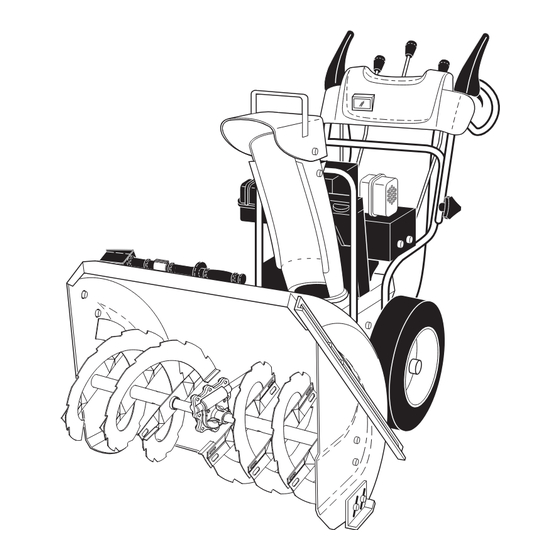
OPERATION KNOW YOUR SNOW THROWER READ THIS OWNER'S MANUAL AND ALL SAFETY RULES BEFORE OPERATING YOUR SNOW THROWER. Compare the illustrations with your snow thrower to familiarize yourself with the location of various controls and adjustments. Save this manual for future reference. These symbols may appear on your snow thrower or in literature supplied with the product. - Page 9 OPERATION DISCHARGE CHUTE GAS O LINE ELECTRIC CONTROL LEVER AUGER DRIVE FILLER CAP START BUTTON CONTROL SPEED DEFLECTOR REMOTE LEVER CON TROL RECOIL CONTROL LEVER LEVER MUF FLER (AUXILIARY) STARTER HANDLE TRACTION CHUTE CHOKE DRIVE DE FLEC TOR CON- CONTROL TROL LEVER PRIM ER...
- Page 10 OPERATION The operation of any snow thrower can result The DIRECTION in which snow is to be thrown is controlled in foreign objects thrown into the eyes, which by the discharge chute control lever. can result in severe eye damage. Always wear •...
-
Page 11: Using The Clean-Out Tool
OPERATION USING THE CLEAN-OUT TOOL (See Fig. 14) CAUTION: Do not move speed con trol le ver In certain snow conditions, the discharge chute may be- when traction drive control lever is en gaged. Damage to the snow thrower can result. come clogged with ice and snow. -
Page 12: Before Starting The Engine
OPERATION TO ADJUST SKID PLATES (See Fig. 17) BEFORE STARTING THE ENGINE TO ADJUST SKID PLATES (See Fig. 17) NOTE: The wrench provided in your parts bag may be CHECK ENGINE OIL LEVEL (See Fig. 19) NOTE: The wrench provided in your parts bag may be used to adjust the skid plates. -
Page 13: Snow Throwing Tips
OPERATION TO START ENGINE 5. Pull recoil starter handle quickly. Do not allow starter rope to snap back. Your snow thrower engine is equipped with both a 120 Volt A.C. electric starter and a recoil starter. The electric starter 6. When the engine starts, release the recoil starter han dle is equipped with a three-wire power cord and plug and is and slowly move the choke control to the “OFF”... -
Page 14: Maintenance
MAINTENANCE GENERAL REC OM MEN DA TIONS LUBRICATION CHART The warranty on this snow thrower does not cover items that have been sub ject ed to operator abuse or negligence. SAE 5W-30 Motor Oil To receive full value from the warranty, operator must maintain snow thrower as in struct ed in this manual. -
Page 15: To Change Engine Oil
MAINTENANCE AUGER GEAR CASE 1. Remove safety ignition key and disconnect spark plug wire from spark plug. Place wire where it cannot come • The gear case was filled with lubricant to the proper in contact with plug. level at the factory. The only time the lubricant needs attention is if service has been performed on the gear 2. -
Page 16: Service And Adjustments
SERVICE AND ADJUSTMENTS WARNING: To avoid serious injury, before performing any service or ad just ments: 1. Be sure the on/off switch is in the OFF position. 2. Remove safety ignition key. 3. Make sure the augers and all mov ing parts have completely stopped. 4. -
Page 17: To Replace Belts
SERVICE AND ADJUSTMENTS TO REPLACE BELTS (See Fig. 22) 8. RELIEVE TENSION ON TRACTION DRIVE BELT IDLER and remove traction drive belt from around The auger and traction drive belts are not adjustable. If pulleys. the belts are damaged or begin to slip from wear, they should be replaced. - Page 18 SERVICE AND ADJUSTMENTS TO REMOVE WHEELS (See Fig. 23) TO ADJUST CABLE TENSION (See Fig. 24) • Remove the klik pin and remove wheel from axle. Adjust cable tension by turning the adjuster turn buckle, located on the right hand cable. Grasp the long section IMPORTANT: When installing wheel, be sure to use the tightly and turn the short section to lengthen the adjuster.
-
Page 19: Storage
STORAGE Immediately prepare your unit for storage at the end of the • Empty the fuel tank by starting the engine and letting it run until the fuel lines and car bu re tor are empty. season or if the unit will not be used for 30 days or more. •... -
Page 20: Troubleshooting
TROUBLESHOOTING See appropriate section in manual unless directed to an authorized service center/department. PROBLEM CAUSE CORRECTION Does not start 1. Fuel shut-off valve (if so 1. Turn fuel shut-off valve to OPEN position. equipped) in OFF position. 2. Safety ignition key 2. - Page 21 SERVICE NOTES...
-
Page 22: Repair Parts
SNOW THROWER - MODEL PP1150E30 (96198003200) REPAIR PARTS AUGER HOUSING / IMPELLER ASSEMBLY (EXPLODED) 01.07.004-C NOTE: All component dimensions given in U.S. inches. 1 inch = 25.4 mm IMPORTANT: Use only Original Equipment Manufacturer (O.E.M.) replacement parts. Failure to do so could be hazardous, damage your snow thrower and void your warranty. - Page 23 SNOW THROWER - MODEL PP1150E30 (96198003200) REPAIR PARTS AUGER HOUSING / IMPELLER ASSEMBLY PART DESCRIPTION 175321X479 IMPELLER 196710 GEARBOX ASSEMBLY 188909 BEARING 191079 IMPELLER PULLEY 175322 DISCHARGE BASE 178675X008 CORNER BRACKET 192199 CLEAN OUT TOOL 405400 TOOL CLIP 73800400 NUT 1/4-20 74780426 SCREW 1/4-20 X .625 427942...
- Page 24 SNOW THROWER - MODEL PP1150E30 (96198003200) REPAIR PARTS AUGER HOUSING / IMPELLER ASSEMBLY PART DESCRIPTION 404930X428 AUGER HOUSING 404933X479 SCRAPPER BAR 72270505 CARRIAGE BOLT 5/16−18 X .625 155377 NUT 5/16−18 3 (5x) 4 (5x) 01.07.003-A PART DESCRIPTION 420497X421 AUGER ASSEMBLY 30 LH 420498X421 AUGER ASSEMBLY 30 RH 01.07.019-A...
- Page 25 SNOW THROWER - MODEL PP1150E30 (96198003200) REPAIR PARTS AUGER HOUSING / IMPELLER ASSEMBLY PART DESCRIPTION 420478 AUGER BEARING 411939 BEARING PLUG 179582 SCREW 5/16−18 X 1.00 01.07.024-B PART DESCRIPTION 174762X479 SKID PLATE LH 178777X479 SKID PLATE RH 72270506 CARRIAGE BOLT 5/16−18 X .75 751153 NUT 5/16−18 01.11.001-A...
- Page 26 SNOW THROWER - MODEL PP1150E30 (96198003200) REPAIR PARTS AUGER HOUSING / IMPELLER ASSEMBLY PART DESCRIPTION 181160X479 DRIFT CUTTER BAR 72270506 CARRIAGE BOLT 5/16−18 X .750 179246 PLASTIC WASHER 10040500 LOCKWASHER 5/16 128638 NUT 5/16−18 01.16.001-A...
- Page 27 SNOW THROWER - MODEL PP1150E30 (96198003200) REPAIR PARTS CONTROL PANEL / DISCHARGE CHUTE PART DESCRIPTION 404770X428 CHUTE WELDMENT 178633X428 DEFLECTOR WELDMENT 420673 DEFLECTOR CONTROL ASSEMBLY 420325 DEFLECTOR SEAL 414280 KNOB BLACK 128415 POP RIVET 17501010 SCREW 10-24 X .625 179829 SHOULDER SCREW 191730 NUT 1/4-20...
- Page 28 SNOW THROWER - MODEL PP1150E30 (96198003200) REPAIR PARTS CONTROL PANEL / DISCHARGE CHUTE PART DESCRIPTION 428272 LEVER/CABLE ROTATOR ASSEMBLY 17501010 SCREW 10-24 X .625 420678 ROTATOR HEAD 01.09.010-A 405932 ROTATOR PIVOT BRACKET 420675 PULLEY PIVOT 428273 CABLE ASSEMBLY ADJUSTABLE 428310 CABLE ASSEMBLY HEAT SHIELD NOTES: 1.
- Page 29 SNOW THROWER - MODEL PP1150E30 (96198003200) REPAIR PARTS HANDLES PART DESCRIPTION 419798X479 LOOP HANDLE LH 419799X479 LOOP HANDLE RH 74780524 SCREW 5/16−18 X 1.50 751153 NUT 5/16−18 01.08.004-B PART DESCRIPTION 419797X479 LOWER TUBE 418313X479 PIVOT SUPPORT 428867 BOLT 5/16-18 X .750 17000616 SCREW 3/8-16 X 1.00 01.05.004-C...
- Page 30 SNOW THROWER - MODEL PP1150E30 (96198003200) REPAIR PARTS HANDLES PART DESCRIPTION 180480 IMPELLER ROD 405740 TRACTION ROD 180445 SHIFTER ROD TOP 187716 SHIFTER ROD BOTTOM 180447 SPRING SLEEVE 178669 IMPELLER SPRING 180926 TRACTION SPRING 72270505 CARRIAGE BOLT 5/16-18 X .625 155377 NUT 5/16-18 169675...
- Page 31 SNOW THROWER - MODEL PP1150E30 (96198003200) REPAIR PARTS HANDLES 01.08.002-F PART DESCRIPTION 412683X479 CONTROL PANEL 424517X479 CONTROL LEVER LH 424516X479 CONTROL LEVER RH 426917X008 TRACTION ROD ARM 426918X008 IMPELLER ROD ARM 412677 INTERLOCK ROD 421613 SPACER 169675 RETAINER 17060410 SCREW 1/4-20 X .62 414280 KNOB BLACK 414281...
- Page 32 SNOW THROWER - MODEL PP1150E30 (96198003200) REPAIR PARTS HANDLES PART DESCRIPTION 412675X004 INTERLOCK SPRING 414572 INTERLOCK CAM 178831 TORSION SPRING 169675 RETAINER 17060410 SCREW 1/4−20 X .625 421252X004 INTERLOCK STOP 01.08.007-B PART DESCRIPTION 182906 CONSOLE PANEL 178668 HEADLIGHT BEZEL 180927 FLOOD HEADLIGHT 184471 SHOULDER SCREW 10−24 X...
- Page 33 SNOW THROWER - MODEL PP1150E30 (96198003200) REPAIR PARTS DRIVE 01.03.002-A PART DESCRIPTION 404923 AXLE ASSEMBLY (assy of 1a,1b) 404307 AXLE SHAFT 9456M1 ROLL PIN 3/16 X 1.50 402691 SPROCKET 174697 THRUST WASHER 179830 BEARING 146315 SCREW 5/16−18 X .625 17490508 SCREW 5/16−18 X .500 155443 KLIK PIN 1/4 X 1.50...
- Page 34 SNOW THROWER - MODEL PP1150E30 (96198003200) REPAIR PARTS DRIVE ITEM 42 EXPLODED 01.02.012-A NOTE: All component dimensions given in U.S. inches. 1 inch = 25.4 mm IMPORTANT: Use only Original Equipment Manufacturer (O.E.M.) replacement parts. Failure to do so could be hazardous, damage your snow thrower and void your warranty.
- Page 35 SNOW THROWER - MODEL PP1150E30 (96198003200) REPAIR PARTS DRIVE PART PART DESCRIPTION DESCRIPTION 175344 BEARING 198875 SPEED SELECTOR ASSEMBLY 178613 WHEEL HUB 17501010 SCREW 10-24 X .625 74760514 SCREW 5/16-18-.875 402685X428 END PLATE 12000012 RETAINER RING 17490508 SCREW 5/16-18 X .50 402187 SPROCKET SHAFT 57079...
- Page 36 SNOW THROWER - MODEL PP1150E30 (96198003200) REPAIR PARTS CHASSIS / ENGINE / PULLEYS PART DESCRIPTION - - - - - - B&S ENGINE MODEL 15C114-0939-E8 418694X428 FRAME 150406 BOLT 3/8-16 01.00.034-A 428867 SCREW 5/16-18 X .750 PART DESCRIPTION 423185X428 ENGINE MOUNTING PLATE 01.01.003-A NOTE: All component dimensions given in U.S.
- Page 37 SNOW THROWER - MODEL PP1150E30 (96198003200) REPAIR PARTS CHASSIS / ENGINE / PULLEYS PART DESCRIPTION 408007 IMPELLER BELT 419744 TRACTION BELT 419925X479 IDLER ARM 193397X479 IDLER BRACKET 180523 IDLER PULLEY 74780524 SCREW 5/16-18 X 1.50 426589 NUT 5/16-18 175330 IDLER ARM PIN 85179 RETAINER CLIP 428867...
- Page 38 SNOW THROWER - MODEL PP1150E30 (96198003200) REPAIR PARTS WHEELS PART DESCRIPTION 405161 COVER 184471 SHOULDER SCREW 12000045 RETAINER RING 192126 WHEEL DRIVER 182466 RETAINER RING 187622 WHEEL LOBE 194941 CLUTCH SLIDE 01.15.001-A 179139 SPRING 189282 SQUARE KEY 194940 AXLE LOBE 174697 THRUST WASHER 193506X479...
- Page 39 SNOW THROWER - MODEL PP1150E30 (96198003200) REPAIR PARTS WHEELS PART DESCRIPTION 192092X421 WHEEL 16 X 4.80 X LH 192093X421 WHEEL 16 X 4.80 X RH 01.06.005-A NOTE: All component dimensions given in U.S. inches. 1 inch = 25.4 mm IMPORTANT: Use only Original Equipment Manufacturer (O.E.M.) replacement parts. Failure to do so could be hazardous, damage your snow thrower and void your warranty.
- Page 40 SNOW THROWER - MODEL PP1150E30 (96198003200) REPAIR PARTS BAG OF PARTS PART DESCRIPTION 198563 POWER CORD 169675 RETAINER PIN 180684X008 WRENCH 184505 REMOTE SPRING 179829 SHOULDER BOLT 1/4-20 191730 LOCKNUT 1/4-20 72250505 CARRIAGE BOLT 5/16-18 X 5/8 751153 LOCKNUT 5/16-18 73800600 LOCKNUT 3/8-16 19131316...
- Page 41 SNOW THROWER - MODEL PP1150E30 (96198003200) REPAIR PARTS DECALS PART DESCRIPTION 181037 DECAL, DANGER 181035 DECAL, DANGER, DEFLECTOR 181042 DECAL, DANGER 181033 DECAL, INSTRUCTION 415475 DECAL, SPEED CONTROL 183730 DECAL, REMOTE DEFLECTOR CONTROL 415399 DECAL, LH TRIGGER 415398 DECAL, RH TRIGGER 429247 OWNER’S MANUAL, ENGLISH 429249...
- Page 42 SERVICE NOTES...
- Page 43 SERVICE NOTES...
-
Page 44: Warranty
6. In the event you have a claim under this Warranty, you must return the product to an authorized service dealer. Should you have any unanswered questions concerning this Warranty, please contact: In Canada contact: Poulan Pro Poulan, Customer Service Department Customer Service Department...
Need help?
Do you have a question about the PRO PP1150E30 and is the answer not in the manual?
Questions and answers