Vaisala Humicap HMD60Y User Manual
Humidity and temperature transmitters
Hide thumbs
Also See for Humicap HMD60Y:
- Operating manual (4 pages) ,
- Operating manual (13 pages) ,
- Operating manual (21 pages)

Related Manuals for Vaisala Humicap HMD60Y


Summary of Contents for Vaisala Humicap HMD60Y
- Page 1 USER'S GUIDE ® Vaisala HUMICAP Humidity and Temperature Transmitters HMD60U/Y U301EN11...
- Page 2 The contents are subject to change without prior notice. Please observe that this manual does not create any legally binding obligations for Vaisala towards the customer or end user. All legally binding commitments and agreements are included exclusively in the applicable supply contract or Conditions of...
-
Page 3: Table Of Contents
HMD60U/Y Transmitters U301en-1.1 Operating Manual Contents PRODUCT DESCRIPTION ....................1 TO BE NOTED WHEN MEASURING HUMIDITY ..............2 INSTALLATION........................3 Selecting the place of installation ................3 Mounting ........................3 Grounding ........................ 4 Electrical connections..................... 5 Electronics ....................... 6 CALIBRATION ........................7 One-point humidity calibration ................ - Page 4 HMD60U/Y Transmitters Operating Manual U301en-1.1 This page intentionally left blank. 1997-07-31...
-
Page 5: Product Description
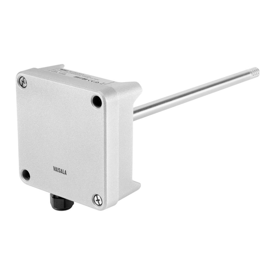
HMD60U/Y Transmitters U301en-1.1 Operating Manual PRODUCT DESCRIPTION The HMD60 transmitters are duct mounted two-wire transmitters for the measurement of humidity (HMD60U) and for the measurement of humidity and temperature (HMD60Y). The HMD60U/Y transmitters are easy to install and maintain: the electronics can be disconnected without dismantling the installation. -
Page 6: To Be Noted When Measuring Humidity
HMD60U/Y Transmitters Operating Manual U301en-1.1 TO BE NOTED WHEN MEASURING HUMIDITY In the measurement of humidity and especially in calibration, it is essential that the temperature equilibrium is reached. Even a slight difference in the temperature between the measured object and the sensor causes an error. For example, at +20 C (+ 68 F) and 50 %RH, a temperature difference of +1 C between the measured object and the sensor causes an error of +3 %RH. -
Page 7: Installation
HMD60U/Y Transmitters U301en-1.1 Operating Manual INSTALLATION Selecting the place of installation Select a place that gives a true picture of the environment or process and is as clean as possible. Air should circulate freely around the sensor. A rapid air flow is recommended as it ensures the same temperature for the ambient air and the sensor head. -
Page 8: Grounding
HMD60U/Y Transmitters Operating Manual U301en-1.1 Grounding Open the lid and mount the cable bushing set 18941HM. Do the grounding according to Figure 3.3. When connecting the signal cable to the transmitter housing, fold the cable braid between the brass disk in order to achieve the best possible EMC performance. -
Page 9: Electrical Connections
HMD60U/Y Transmitters U301en-1.1 Operating Manual Electrical connections Connect the signal cables to a removeable 5-pole screw connector. Make connections according to Figure 3.4. RH test and T test connectors are used with the HMI41 indicator and calibration cable 19116ZZ. TEST RH GAIN TEST 3 4 5... -
Page 10: Electronics
HMD60U/Y Transmitters Operating Manual U301en-1.1 Electronics TO REMOVE THE SENSOR HEAD: 1. Open the lid 2. Disconnect the screw terminal 3. Open the screws (2 pcs) 4. Pull out carefully SCREW TERMINAL TO REINSTALL THE SENSOR HEAD: SCREWS 1. Push in the sensor head 2. -
Page 11: Calibration
LiCl (11 %RH) and NaCl (75 %RH) solutions. Two-point humidity calibration The calibration can also be done with salt calibrators, or the instrument can be sent to Vaisala or a Vaisala representative. 4.2.1 Two-point humidity calibration procedure Leave the calibrator and the transmitter for at least 30 minutes in the same space so that their temperatures have time to equalize. -
Page 12: Calibration Table
HMD60U/Y Transmitters Operating Manual U301en-1.1 Calibration table Temperature °C °F LiCl 11.3 11.3 11.3 11.3 4...20 mA 5.81 5.81 5.81 5.81 0...20 mA 2.26 2.26 2.26 2.26 0...1 V 0.113 0.113 0.113 0.113 0...5 V 0.565 0.565 0.565 0.565 0...10 V 1.13 1.13 1.13... -
Page 13: Technical Data
HMD60U/Y Transmitters U301en-1.1 Operating Manual TECHNICAL DATA Relative humidity Measurement range 0...100 %RH Accuracy at +20 C: % R H 1 0 0 Temperature dependence: - 2 0 - 1 0 ° C -0.5 -1.0 -1.5 -2.0 Humidity sensor HUMICAP 180 Response time (90%) at 20 C in still air 15 s with membrane filter Temperature (Y model only) -
Page 14: General
HMD60U/Y Transmitters Operating Manual U301en-1.1 General Supply voltage 10...35 VDC (R L = 0 ) 20...35 VDC (R L =500 ) Output signal 4...20 mA Operating temperature range: electronics -5...+55 C sensor head -40...+80 C Storage temperature range -40...+80 C Housing: sensor head stainless steel... -
Page 15: Electromagnetic Compatibility
ENV50204:1995 criteria A (*additional test) GUARANTEE Vaisala issues a guarantee for the material and workmanship of this product under normal operating conditions for one year from the date of delivery. Exceptional operating conditions, damage due to careless handling or misapplication will void the guarantee. - Page 18 www.vaisala.com...
Need help?
Do you have a question about the Humicap HMD60Y and is the answer not in the manual?
Questions and answers