Harman Kardon AVR 1650 Owner's Manual
Harman-kardon stereo receiver user manual
Hide thumbs
Also See for AVR 1650:
- Service manual (111 pages) ,
- Owner's manual (56 pages) ,
- User manual (13 pages)
Table of Contents
Advertisement
Advertisement
Table of Contents
Troubleshooting

Related Manuals for Harman Kardon AVR 1650


Summary of Contents for Harman Kardon AVR 1650
- Page 1 AVR 1650/AVR 165 Audio/video receiver Owner’s Manual...
-
Page 2: Table Of Contents
INTRODUCTION SUPPLIED ACCESSORIES IMPORTANT SAFETY INFORMATION PLACE THE AVR FRONT-PANEL CONTROLS REAR-PANEL CONNECTORS SYSTEM REMOTE CONTROL FUNCTIONS INTRODUCTION TO HOME THEATER TYPICAL HOME THEATER SYSTEM MULTICHANNEL AUDIO SURROUND MODES PLACE YOUR SPEAKERS PLACING THE LEFT, CENTER AND RIGHT SPEAKERS PLACING THE SURROUND SPEAKERS PLACING THE SUBWOOFER TYPES OF HOME THEATER SYSTEM CONNECTIONS SPEAKER CONNECTIONS... -
Page 3: Introduction
IMPORTANT SAFETY INFORMATION Verify Line Voltage Before Use The AVR 1650 has been designed for use with 120-volt alternating current (AC). The AVR 165 has been designed for use with 220 – 240-volt AC. Connection to a line voltage other than that for which your AVR is intended can create a safety and fire hazard, and may damage the unit. -
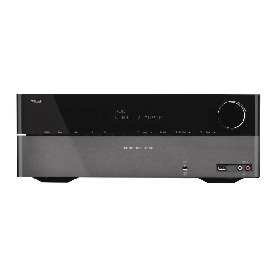
Page 4: Front-Panel Controls
AVR 1650/AVR 165 Front-Panel Controls Front-Panel Controls Power Message Surround Mode Volume Indicator Sensor Button Display Select Buttons Knob Power Channel Left/Right Up/Down Buttons/ Headphone Jack/ Aux Analog Button Level Control Buttons Tuning Buttons EzSet/EQ Mic Port Audio Input Button... - Page 5 Front-Panel Controls, continued Power indicator: This LED has three possible modes: • LED is off: Indicates that the AVR is unplugged or the rear-panel Main Power switch is off. • LED glows amber: Indicates that the AVR is in the Standby mode. •...
-
Page 6: Rear-Panel Connectors
Monitor Out Connector HDMI Input Radio Antenna Connectors Connectors Analog Audio Input/Output Connectors Subwoofer Connector AVR 1650/AVR 165 Rear-Panel Connections (AVR 1650 shown) Composite Video Video 2 Out Monitor Out Connector Connector Composite Video Input Component Video Connectors Input Connector... - Page 7 Rear-Panel Connectors, continued Radio Antenna connectors: Connect the included AM and FM antennas to their respective terminals for radio reception. HDMI Monitor Out connector: If your TV has an HDMI connector and you have HDMI or component video source devices, use an HDMI cable (not included) to connect it to the AVR’s HDMI Monitor Out connector.
-
Page 8: System Remote Control Functions
Source Selector Buttons Volume Up/Down Buttons Speaker Setup Buttons OK Button Delay Button Left/Right/Up/Down Buttons Number Buttons Memory Button Clear Button Preset Station Up/Down Buttons Disc Skip Button (AVR 1650) RDS Button (AVR 165) Macro Buttons Display Dimmer Button Transport Control Buttons... - Page 9 Tone Control button: Press this button to access the bass and treble controls. Use the OK button to select an adjustment and use the Up/Down buttons to change the settings. Disc Skip button (AVR 1650): This button is used with some optical disc changers to skip to the next disc.
-
Page 10: Introduction To Home Theater
AVR 1650/AVR 165 Introduction to Home Theater This introductory section will help you to familiarize yourself with some basic concepts unique to multichannel surround-sound AVRs, which will make it easier for you to set up and operate your AVR. Typical Home Theater System A home theater typically includes an audio/video receiver (AVR), which controls the system and supplies amplification for the loudspeakers;... -
Page 11: Types Of Home Theater System Connections
Types of Home Theater System Connections There are different types of audio and video connections used to connect the AVR to your speakers, your TV or video display, and your source devices. The Consumer Electronics Association has established the CEA ®... -
Page 12: Video Connections
AVR 1650/AVR 165 Digital Audio Connections – Optical Optical digital audio connectors are normally covered by a shutter to protect them from dust. The shutter opens as the cable is inserted. Optical input connectors are color- coded using a black shutter, while optical outputs use a gray shutter. -
Page 13: Making Connections
Making Connections CAUTION: Before making any connections to the AVR, ensure that the AVR’s AC cord is unplugged from the AVR and the AC outlet. Making connections with the AVR plugged in and turned on could damage the speakers. Connect Your Speakers After you have placed your loudspeakers in the room as explained in Place Your Speakers, on page 10, connect each speaker to its color-coded terminal on the AVR as explained in Speaker Connections, on page 11. - Page 14 HDMI devices If any of your source devices have HDMI connectors, using those connectors will provide the best possible video and audio performance quality. Since the HDMI cable carries both digital video and digital audio signals, you do not have to make any additional audio connections for devices you connect via HDMI cables, although you can assign one of the digital audio connectors to one of the HDMI inputs.
-
Page 15: Connect Your Source Devices
AVR 1650/AVR 165 Audio recorders Connect an analog audio recorder’s inputs to the AVR’s analog audio Tape Out connectors. You can record any analog audio input signal. AVR Analog Audio Recorder Connectors Stereo Audio Cable (not supplied) Analog Recording Device You can connect the AVR’s Optical Digital Output connector to a digital audio recorder’s... -
Page 16: Connect The 12V Trigger Output
AVR 1650/AVR 165 Connect the 12V Trigger Output If your system has equipment that can be controlled by a DC trigger signal, connect it to the AVR’s 12V Trigger connector with a mono 1/8-inch (3.5mm) mini-plug interconnect cable. The AVR will supply a 12V DC (100mA) trigger signal at this connection whenever it is powered on. -
Page 17: Set Up The Avr
Set Up the AVR Turn On the AVR 1. Set the rear-panel Main Power switch to “On.” (The front-panel Power indicator will glow amber.) 2. Press the front-panel Power button. Main Power Switch Unless you will not be using the AVR for an extended period of time, leave the Main Power switch set to “On.”... -
Page 18: Assign The Digital Audio Connectors
Assign the Digital Audio Connectors 1. Review the input connections you listed on the Input Connections and Source Buttons table, on page 13. Note which source devices you connected to the digital audio connectors. (If you did not connect any source devices to the digital audio connectors, you can skip this section.) 2. -
Page 19: Operating Your Avr
Operating Your AVR Now that you have installed your components and completed a basic configuration, you are ready to begin enjoying your home theater system. Controlling the Volume Adjust the volume either by turning the front-panel Volume knob (clockwise to increase volume or counterclockwise to decrease volume) or by pressing the Volume Up/Down buttons on the remote. -
Page 20: Selecting A Surround Mode
AVR 1650/AVR 165 Selecting a Surround Mode Selecting a surround mode can be as simple or sophisticated as your individual system and tastes. Feel free to experiment, and you may find a few favorites for certain sources or program types. You can find more detailed information on surround modes in Audio Processing and Surround Sound, on this page. -
Page 21: Advanced Functions
Audio (7.1), DTS-HD Master Audio (7.1), DTS 5.1, DTS 96/24 (5.1), 2-channel PCM modes in 32kHz, 44.1kHz, 48kHz or 96kHz, and 5.1 or 7.1 multichannel PCM. (Your AVR will downmix the discrete surround back-channel information in 6.1-channel and 7.1-channel recordings into your system’s surround left and surround right channels.) When the AVR receives a digital bitstream, it detects the encoding method and the number of channels, which is displayed briefly as three numbers, separated by slashes (e.g., “3/2/.1”). - Page 22 Step Two – Measure the Speaker Distances Ideally, all of your speakers would be placed in a circle, with the listening position at the center. However, you may have had to place some speakers a little farther away from the listening position than others.
-
Page 23: System Setup
Step Four – Setting Channel Output Levels Manually For a conventional stereo AVR, a simple balance control adjusts the stereo imaging by varying the relative loudness of the left and right channels. In a home theater system with up to seven main channels plus a subwoofer, achieving proper imaging becomes both more critical and more complex. -
Page 24: Advanced Remote Control Programming
Advanced Remote Control Programming Remote Channel-Control Punch-Through The punch-through feature allows you to operate one component while setting certain groups of controls to operate another component. For example, while using the AVR controls for surround modes and other audio functions, you may also use the remote to operate the transport controls of your Blu-ray Disc player. -
Page 25: Troubleshooting
Troubleshooting Symptom Unit does not function when Main Power switch is turned on Front-panel Message display lights, but there's no sound or picture No sound from any speaker; PROTECT message appears on Message display No sound from center or surround speakers Unit does not respond to remote control commands Intermittent buzzing in tuner Unable to activate remote control Programming mode... -
Page 26: Audio Section
70dB 80dB 90dB 520 – 1720kHz 45dB 500μV 0.8% 30dB Specifications NTSC (AVR 1650); PAL (AVR 165) 1Vp-p/75 ohms 1Vp-p/75 ohms 10Hz – 8MHz (–3dB) Version 1.4a with 12-bit Deep Color 120V AC/60Hz (AVR 1650); 220V – 240V AC/50Hz – 60Hz (AVR 165) <0.5W (standby);... -
Page 27: Appendix
Appendix – Default settings, worksheets, remote product codes Table A1 – Recommended Source Component Connections Device Type Cable TV, Satellite, HDTV or other device that delivers television programs VCR, DVR, PVR, or other audio/video recorder DVD player, Blu-ray Disc player HDMI-capable disc player, game console or other audio/video device HDMI-capable disc player, game console or... - Page 28 Table A3 – Speaker/Channel Setting Defaults Source All Sources Left/Right Speaker Center Speaker Surround Speaker Surround Back Speaker Subwoofer 100Hz Left/Right Speaker Crossover 100Hz Center Speaker Crossover 100Hz Surround Speaker Crossover 100Hz Surround Back Speaker Crossover PRESENT Sub Mode Table A4 – Distance Settings Speaker Positions Your Distances From Speaker to Listening Position Front Left...
- Page 29 Table A5 – Source Settings Source HDMI 1 Title Video Input Component Video Input Digital Audio Input Analog Audio Input Auto Poll Table A6 – Speaker/Channel Settings Front Left Number of Speakers Crossover Distance Channel Level Adjust HDMI 2 HDMI 3 HDMI 4 Video 1 VIDEO 1...
-
Page 30: Default Setting
Table A7 – Remote Control Codes Source Input Product Type (circle one) VCR, PVR, DMC Video 1 Video 2 Cable, Satellite HDMI 1 DVD, Blu-ray Disc player, VCR/PVR/DMC, Cable/Satellite DVD, Blu-ray Disc player, VCR/PVR/DMC, Cable/Satellite HDMI 2 DVD, Blu-ray Disc player, VCR/PVR/DMC, Cable/Satellite HDMI 3 DVD, Blu-ray Disc player, VCR/PVR/DMC, Cable/Satellite HDMI 4... - Page 31 Table A9 – Surround Modes Surround Mode Description Dolby Digital Provides up to five separate main audio channels and a dedicated low-frequency effects (LFE) channel. Dolby Digital Plus An enhanced version of Dolby Digital encoded more efficiently, Dolby Digital Plus has the capacity for additional discrete channels and for streaming audio from the Internet, all with enhanced audio quality.
- Page 32 Table A9 – Surround Modes (cont.) Surround Mode Description Using a different encoding/decoding method from Dolby Digital, DTS Digital DTS Digital also provides up to five discrete main channels, plus an LFE channel. DTS-HD DTS-HD is a high-definition audio format that complements the high-definition video found on Blu-ray Disc and HD-DVD discs.
- Page 33 AVR 1650/AVR 165 Appendix Refer to the numbered buttons when using the Function ListRemote Control...
- Page 34 Table A10 – Remote Control Function List No. Button Name AVR Function Power On Power On Power On Power Off Power Off Power Off Mute Mute Mute AVR Select AVR Select DVD Select DVD Select VID 1 (VCR) Video 1 Select VCR Select HDMI 1 HDMI 1 Select HDMI 1 Select HDMI 1 Select HDMI 1 Select HDMI 1 Select HDMI 1 Select HDMI 1 Select HDMI 1 Select HDMI 1 Select HDMI 1 Select HDMI 1 Select...
- Page 35 Table A10 – Remote Control Function List (cont.) No. Button Name AVR Function Chapter+ or Tun-M Tuner Mode Zoom Memory Memory Audio or Playlist Tuning Up Tuning Up Next Chapter Direct Tuner Direct Angle Entry Clear Clear Clear Preset Up Preset Tune Up Slow Forward Tuning Down Tuning Down...
- Page 36 Table A11 – Remote Control Product Codes: TV TV Manufacturer/Brand Setup Code Number ADMIRAL ANAM 045 106 109 112 122 037 122 123 128 AUDIOVOX BLAUPUNKT BROKSONIC 205 206 CITIZEN 045 123 128 132 CONTEC CRAIG 045 157 158 159 CROWN 045 132 CURTIS MATHES...
- Page 37 Table A11 – Remote Control Product Codes: TV (cont.) TV Manufacturer/Brand Setup Code Number SANYO 026 054 SCOTT 045 128 132 SEARS 128 132 145 SHARP 077 128 132 SIEMENS SIGNATURE SONY 028 031 117 130 136 194 212 SOUNDESIGN 045 128 SYLVANIA 025 123 128 145 148...
- Page 38 Table A12 – Remote Control Product Codes: VCR (cont.) VCR Manufacturer/Brand Setup Code Number SYLVANIA SYMPHONIC TANDY 017 040 TEAC 040 048 TEKNIKA THOMAS TiVo 004 005 006 007 008 009 011 012 TOSHIBA 112 155 TOTEVISION UNITECH VECTOR RESEARCH VIDEO CONCEPTS 018 040 VIDEOSONIC...
- Page 39 Table A13 – Remote Control Product Codes: CD (cont.) CD Manufacturer/Brand Setup Code Number PROTON RADIO SHACK 126 166 213 024 081 093 150 REALISTIC 058 093 095 104 105 108 164 166 SANSUI 047 081 134 157 172 SANYO 033 082 095 SCOTT SHARP...
- Page 40 Table A15 – Remote Control Product Codes: SAT (cont.) SAT Manufacturer/Brand Setup Code Number HUGHES 305 306 437 489 JANIEL JERROLD 454 468 484 LEGEND MACOM 317 365 369 370 371 MAGNAVOX 461 473 MEMOREX MITSUBISHI MOTOROLA 312 319 NEXTWAVE NORSAT OPTIMUS PACE...
- Page 41 Table A17 – Remote Control Product Codes: Cable (cont.) Cable Manufacturer/Brand Setup Code Number PHILIPS 013 019 020 085 090 PIONEER 001 041 119 171 209 215 216 RADIO SHACK 111 112 213 053 214 RECOTON REGAL 056 099 100 101 208 REMBRANDT SAMSUNG 003 072 186...
- Page 42 HARMAN Consumer, Inc. 8500 Balboa Boulevard, Northridge, CA 91329 USA © 2011 HARMAN International Industries, Incorporated. All rights reserved. Harman Kardon and Logic 7 are trademarks of HARMAN International Industries, Incorporated, registered in the United States and/or other countries. EzSet/EQ is a trademark of HARMAN International Industries, Incorporated. Apple, iPhone, iPod, iPod touch, iPod nano and iPod classic are trademarks of Apple Inc., registered in the U.S.
Need help?
Do you have a question about the AVR 1650 and is the answer not in the manual?
Questions and answers