Table of Contents
Advertisement
CAUTION
RISK OF ELECTRIC SHOCK
DO NOT OPEN
The lightning flash with arrowhead symbol, within an equilateral triangle, is intended to alert the user
to the presence of uninsulated "dangerous voltage" within the product's enclosure that may
be of sufficient magnitude to constitute a risk of electric shock to persons.
The exclamation point within an equilateral triangle is intended to alert the user to the
presence of important operating and maintenance (servicing) instructions in the litera-
ture accompanying the appliance.
WARNING: TO PREVENT FIRE OR SHOCK HAZARD, DO
NOT EXPOSE THIS APPLIANCE TO RAIN OR
MOISTURE.
STR-84
260 WATT STEREO RECEIVER
CAUTION: TO REDUCE THE RISK OF ELECTRIC SHOCK, DO NOT
REMOVE COVER (OR BACK). NO USER-SERVICEABLE PARTS INSIDE.
REFER SERVICING TO QUALIFIED SERVICE PERSONNEL.
OWNER'S MANUAL
Advertisement
Table of Contents

Summary of Contents for TECHWOOD STR-84
- Page 1 STR-84 260 WATT STEREO RECEIVER OWNER’S MANUAL CAUTION: TO REDUCE THE RISK OF ELECTRIC SHOCK, DO NOT CAUTION REMOVE COVER (OR BACK). NO USER-SERVICEABLE PARTS INSIDE. RISK OF ELECTRIC SHOCK DO NOT OPEN REFER SERVICING TO QUALIFIED SERVICE PERSONNEL. The lightning flash with arrowhead symbol, within an equilateral triangle, is intended to alert the user to the presence of uninsulated “dangerous voltage”...
-
Page 2: Important Safety Instructions
IMPORTANT SAFETY INSTRUCTIONS CAUTION: “Note to CATV system installer: • This reminder is provided to call the CATV system installer’s attention Read all of these instructions. • to Section 820-40 of the NEC which provides guidelines for proper Save these instructions for later use. •... -
Page 3: Table Of Contents
CONTENTS IMPORTANT SAFETY INSTRUCTIONS ............................2 PRECAUTIONS ....................................4 Read This Before Operating ................................4 CONNECTIONS ....................................5 System Connections ..................................5 Antenna Connections...................................6 FM Antenna ....................................6 AM (MW) Antenna ..................................6 Speaker Connections ..................................7 Power Cord ....................................7 AC OUTLETS ....................................7 VIDEO 3 INPUT Jacks.................................7 CONTROLS AND INDICATORS ..............................8 Front Panel ....................................8 Display .......................................10 REMOTE CONTROL UNIT ................................11... -
Page 4: Precautions
PRECAUTIONS For U.S.A Read This Before Operating TO THE USER Choose the installation location of your unit carefully. This equipment has been tested found Avoid placing it in direct sunlight or close to a source of comply with the limits for a A/V receiver, pursuant to heat. -
Page 5: Connections
CONNECTIONS : Audio signal System Connections : Video signal CAUTION : Do not plug the power cord of any component into AC outlets and do not turn their POWER switches on until all connections have been performed. Refer to “Antenna Connections” on pages 6~7. TV Monitor Turntable Tape Deck... -
Page 6: Antenna Connections
Antenna Connections AM (MW) Antenna AM Indoor Loop Antenna FM Antenna A high-performance AM loop antenna provided with the receiver is sufficient for good reception in most areas. FM Indoor Antenna Connect the loop antenna’s wires to the AM antenna ter- In an area with strong FM signals, the “T“-type FM antenna minals as shown. -
Page 7: Speaker Connections
Speaker Connections Power Cord Caution : Be sure to connect the power cord to an AC outlet which To avoid damaging the speakers, be sure the power is off supplies the correct 120 voltage. before connecting the speakers. Connect each speaker to the corresponding speaker AC OUTLETS terminal. -
Page 8: Controls And Indicators
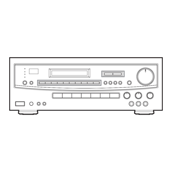
CONTROLS AND INDICATORS Front Panel 1. STANDBY/ ON button and Indicator 10. BALANCE control When in standby mode, a red indicator will light up. Use to balance volume between the left and right main When you press the POWER button, power will be turned speakers. - Page 9 20. BAND selector button 14. SLEEP button Each time you press the button, the bands will 15. Preset buttons (0 -9) change as follows. These buttons are used to store and recall FM/AM sta- tions in memory (See page 17). 16.
-
Page 10: Display
Display 1. Input source, frequency and level indicator 4. TAPE Monitor indicator Function display : This indicator will illuminate When you press TAPE When you press input selection button, the selected input MONITOR button. source will be shown. 5. STEREO indicator Frequency display : When you select Tuner input source, FM/AM frequency This indicator will illuminate when FM stereo broadcasting... -
Page 11: Remote Control Unit
REMOTE CONTROL UNIT Using the Remote Control Unit Battery Installation By using the provided remote control unit, the receiver and matched optional components CDC-85 and TDX-85 can be controlled from your listening position. To use the remote control unit, point it at the REMOTE SENSOR window of the receiver. -
Page 12: Remote Control Unit
Remote Control Unit POWER SELECTION 1. POWER ON button 2. POWER STANDBY button TUNER SECTION 3. SLEEP button 4. TUNING UP/DOWN buttons 5. P.CALL UP/DOWN buttons 6. NUMERIC keys 7. BAND selector button 8. DIRECT TUNING button AMP SECTION 9. INPUT SOURCE Selector buttons 10. -
Page 13: Audio Operations
AUDIO OPERATIONS Back-up memory function WHEN TO USE RESET SWITCH BACK-UP memory Ocassionally, the microprocessor inside the unit may mal- This function stores the preset memory and most-recent function due to electrical power surges or lightning storms. If memory functions. In the event of a power failure, or if the the unit or display malfunctions, try resetting the micro- power cord of this unit is disconnected from the electric out- processor as shown. -
Page 14: Basic Operations
Basic Operations Audio Adjustments POWER STANDBY / ON Button Press this button to turn the power on. Press it again to turn the system off (power standby mode). 1. Set the MASTER VOLUME control to “0”. This is to pro- The indicator lights up in power standby mode and goes out tect the speakers from a sudden high-level signal. -
Page 15: Radio Reception
Radio Reception Manual Tuning Manual Tuning is generally used to tune to stations broad- Auto Tuning casting a signal that is too weak to be received by Auto Tuning. 1. Press the TUNER input selector. 2. Select AM or FM by pressing the BAND selector button. 3. -
Page 16: Direct Tuning With Remote Control
Direct Tuning With Remote Control You can tune a station directly by inputting the actual fre- quency using the remote control. 1. Press the TUNER button. 2. Select AM or FM by pressing the BAND selector button. 3. Press the DIRECT TUNING button on the remote control unit, “ENTER FREQUENCY”... -
Page 17: Preset Tuning
Preset Tuning Manual Memory Presetting This feature is used to store up to 30 FM, AM stations in memory. Automatic Memory Presetting 1. Press the TUNER input selector. 2. Select AM or FM by pressing the BAND selector button. 1. Press the TUNER input selector. 3. -
Page 18: Listening To Records And Compact Discs
1. Make sure the TAPE MONITOR button is set to OFF, An optional phono turntable can be connected to the then press the source selector button corresponding to STR-84. However the turntable must be equipped with the source to be recorded. a magnetic type cartridge. -
Page 19: Video Operations
Video Editing Function the speakers, provided both are properly connected to This feature lets you replace the sound from a VCR with the STR-84 as shown on page 5. sound from an AUDIO source such as CD during video sig- nal dubbing. -
Page 20: Troubleshooting
TROUBLESHOOTING To determine any problem with your receiver, always check the most obvious possible causes first. If any problem still remains after your have checked the items below, consult your nearest TECHWOOD dealer. Problem Probable Cause Remedy Amplifier When listening to the music in stereo, Speakers are connected wrong. -
Page 21: Specifications
SPECIFICATIONS Amplifier Section AM Tuner Section Output Power (Front) : Tuning Range : F.T.C. Rating : 530 kHz - 1,720 kHz (10 kHz steps) 260 Watts total. (U.S.A./Canada) 130 watts RMS per channel minimum, both channels Usable Sensitivity : 55 dB/m driven into 8 ohms from 20 Hz to 20 kHz with no more Total Harmonic Distortion : 0.8% at 85 dB/m than 0.9% total harmonic distortion(U.S.A./Canada) - Page 22 WELTON U.S.A. 11625 COLUMBIA CENTER DR. SUITE 100 DALLAS, TEXAS 75229 PHONE: 972-243-5602 KQX1A448Z FAX: 972-243-5958...
Need help?
Do you have a question about the STR-84 and is the answer not in the manual?
Questions and answers
Why does my receiver say protect when you turn it on.