Table of Contents
Advertisement
Advertisement
Table of Contents

Summary of Contents for RSD AX 3500
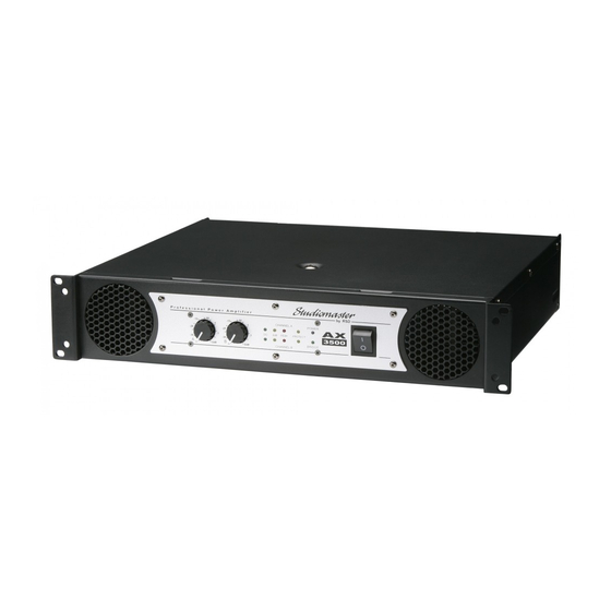
- Page 1 1500 2500 3500 Professional Power Amplifiers USER GUIDE...
-
Page 2: Table Of Contents
STUDIOMASTER AX Amplifier Series Contents Instructions Unpacking Safety Instructions Front panel controls and features Rear panel controls and features 3 - 5 Operation Ventilation Protect LEDs Cables Rack Mounting Trouble Shooting Service Information Technical Information Technical Specification 9 - 10 Glossary of Terms Set-up Diagrams Mono Mix... -
Page 3: Unpacking
STUDIOMASTER AX Amplifier Series Congratulations on your purchase of a Studiomaster AX Series power amplifier. Like all Studiomaster products, it has been designed to meet the highest standards of performance, safety and reliability. We are confident that this amplifier will fully meet your needs for many years to come. -
Page 4: Front Panel Controls And Features
STUDIOMASTER AX Amplifier Series Front panel controls and features P r o f e s s i o n a l P o w e r A m p l i f i e r CHANNEL A POWER -6dB PEAK PROTECT 2500 BRIDGE... -
Page 5: Rear Panel Controls And Features
STUDIOMASTER AX Amplifier Series Rear panel controls and features PIN 1+ = XOVER PIN 1- = 35Hz TO CH A - AMP CAUTION RISK OF ELECTRIC SHOCK DO NOT OPEN XOVER OUTPUT LIMITER LINK INPUT A PARALLEL 100Hz BRIDGE PIN 1+ = LIFT INPUTS 150Hz... - Page 6 STUDIOMASTER AX Amplifier Series Rear panel controls and features PIN 1+ = XOVER PIN 1- = 35Hz TO CH A - AMP CAUTION RISK OF ELECTRIC SHOCK DO NOT OPEN XOVER OUTPUT LIMITER LINK INPUT A PARALLEL 100Hz BRIDGE PIN 1+ = LIFT INPUTS 150Hz...
-
Page 7: Rear Panel Controls And Features
STUDIOMASTER AX Amplifier Series Rear panel controls and features PIN 1+ = XOVER PIN 1- = 35Hz TO CH A - AMP CAUTION RISK OF ELECTRIC SHOCK DO NOT OPEN XOVER OUTPUT LIMITER LINK INPUT A PARALLEL 100Hz BRIDGE PIN 1+ = LIFT INPUTS 150Hz... -
Page 8: Operation
STUDIOMASTER AX Amplifier Series Operation Decide the required mode for the amplifier and select the appropriate rear panel switches. The set up diagrams later in this guide will help. Always ensure that all signal and power connections to the amplifier are properly made before switching on. -
Page 9: Cables
STUDIOMASTER AX Amplifier Series Cables Speaker cables should be as short and as heavy gauge as possible to prevent unwanted power loss caused by high resistance, which can result in loss of both signal level and quality. Heavy duty, twin core A.C. power cable is generally suitable. Cable with a conductor size of 1.5mm²... -
Page 10: Service Information
STUDIOMASTER AX Amplifier Series Service Information If you have a problem with your Studiomaster product or think it has developed a fault you should first carefully check the Trouble Shooting section in this guide. If this does not solve the problem or if the product is physically damaged, contact your local dealer or distributor for service details. -
Page 11: Technical Specification
STUDIOMASTER AX Amplifier Series Technical Specification AX1500 AX2500 AX3500 Power Output in watts per channel At onset of Clipping Both Channels 8 ohms Both Channels 4 ohms 1100 Both Channels 2 ohms 1450 Bridged 8 ohms 1500 2200 Bridged 4 ohms 1150 1980 2900... -
Page 12: Technical Specification
STUDIOMASTER AX Amplifier Series Technical Specification AX1500 AX2500 AX3500 Input Filter 3rd order (18dB / octave) -3dB @ 35Hz 35Hz 35Hz Input Impedance 10k Unbal 10k Unbal 10k Unbal 20k Bal 20k Bal 20k Bal Voltage Gain 35dB 37dB 39dB Cooling Continuously variable speed Twin Fans, back to front airflow. -
Page 13: Glossary Of Technical Terms
STUDIOMASTER AX Amplifier Series Glossary of Technical Terms AC or a.c. Alternating current. IMPEDANCE Similar to resistance, except that AC POWER SUPPLY Local electrical supply impedance also reflects the effect of BALANCED Balanced 3 connection circuitry is any inductance or capacitance in the widely used in audio equipment from circuit. -
Page 14: Mono Mix
STUDIOMASTER AX Amplifier Series Mono Mix Left Speaker Right Speaker Parallel Switch IN PIN 1+ = XOVER PIN 1- = 30Hz TO CH A - AMP XOVER OUTPUT LIMITER LINK INPUT A PARALLEL 100Hz BRIDGE PIN 1+ = LIFT INPUTS CH. -
Page 15: Mono Bi-Amp
STUDIOMASTER AX Amplifier Series Mono Bi-amp Select HI Switch OUT Mid / HI XOVER ON Speaker Switch IN Bass / LO Speaker PIN 1+ = XOVER PIN 1- = 30Hz TO CH A - AMP XOVER OUTPUT LIMITER LINK INPUT A PARALLEL 100Hz BRIDGE... -
Page 16: 2-Way Monitor Mix
STUDIOMASTER AX Amplifier Series 2-way Monitor Mix Stage Monitor Monitor Outputs Stage Monitor Total Load on each channel = NOT less than 2 Ohms PIN 1+ = XOVER PIN 1- = 30Hz TO CH A - AMP eg: If each monitor is 8 Ohms XOVER OUTPUT LIMITER then 8 divide 2 = 4... -
Page 17: 2-Way Stereo With Additional Amplifiers
STUDIOMASTER AX Amplifier Series 2-way Stereo with additional Amplifiers Left Mid / HI Right Speaker Mid / HI Speaker PIN 1+ = XOVER PIN 1- = 30Hz TO CH A - AMP XOVER OUTPUT LIMITER LINK INPUT A PARALLEL 100Hz BRIDGE PIN 1+ = LIFT... -
Page 18: Notes
STUDIOMASTER AX Amplifier Series Notes STUDIOMASTER AX Amplifier Series... - Page 19 STUDIOMASTER AX Amplifier Series Notes STUDIOMASTER AX Amplifier Series...
- Page 20 Recording Studio Design Limited 7 Eden Way, Pages Industrial Park Leighton Buzzard, Bedfordshire LU7 4TZ UK Tel : +44 (0)1525 217111 Fax : +44 (0)1525 378466 email : enquiries@studiomaster.com www.studiomaster.com In Accordance with our progressive product development, Studiomaster / Recording Studio Design reserve the right to change features and specifications without prior notice.
Need help?
Do you have a question about the AX 3500 and is the answer not in the manual?
Questions and answers