
Related Manuals for Fargo Maestro 100

Summary of Contents for Fargo Maestro 100
-
Page 1: User Manual
GSM GPRS Modem 900 / 1800 USER MANUAL Rev. 02 Confidential, the whole present document is the sole property of Fargo Telecom O/B on Fargo Services (HK) Ltd. -
Page 2: Revision History
Fargo Telecom O/B Fargo Services (H.K.) Ltd assumes no liability for damage incurred directly or indirectly from errors, omissions or discrepancies between the modem and the manual. Confidential, the whole present document is the sole property of Fargo Telecom O/B on Fargo Services (HK) Ltd. -
Page 3: Table Of Contents
CONTENTS SAFETY PRECUTIONS CHAPTER 1 INTRODUCTION CHAPTER 2 INSTALLATION CHAPTER 3 WORKING WITH FARGO MAESTRO CHAPTER 4 SPECIFICATION CHAPTER 5 APPENDIX CHAPTER 6 TROUBLESHOOTING - 1 -... -
Page 4: Safety Precutions
SAFETY PRECUTIONS The modem generates radio frequency (RF) power. When using the modem care must be taken on safety issues related to RF interference as well as regulations of RF equipment. Do not use your phone in aircraft, hospitals, petrol stations or in places where using GSM products is prohibited. -
Page 5: Introduction
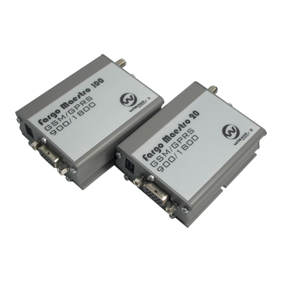
CHAPTER 1 INTRODUCTION Fargo Maestro 100 / Fargo Maestro 20 is a ready-to-use GSM modem for voice, data, fax and SMS services. It also supports GPRS Class 10(Fargo Maestro 100) or Class 2(Fargo Maestro 20) for hi- speed data transfer. Fargo Maestro 100 / Fargo Maestro 20 can be easily controlled by using AT command for all kinds of operations. - Page 6 1.2.3. 15-PIN D-SUB Female connector (RS232 / Audio) The connector provides serial link and audio link to the modem. Pin number Name EIA designation Type Note Data Carrier Detect Output Transmit Data Input BOOT Input Not used MICROPHONE (+) Input With 2V DC bias output MICROPHONE (-)
-
Page 7: Optional Accessories
A cable, included in the package shall be used for power supply connection: 5-32V DC Supply Stripped wire Connector Micro-Fit 3.0 Fuse holder (to Fargo Maestro) Fuse rating : 250V 2.5A Parameters Typical Remark I/O In LOW voltage 0.5V I/O In HIGH voltage I/O out max. - Page 8 ‘Y’ cable Direct connection with standard 9- pin RS-232 port (DTE) Direct connection with common handset of telephone for voice call Shielded cable Cable length 1.1m (w/ connector) Pin Assignment Sub-D 15 Sub-D 9 Plug (male) (female) 4P4C Sub-D 9 pin 4p4c plug DIN rail mount Quick attachment / detachment to...
-
Page 9: Installation
CHAPTER 2 INSTALLATION 2.1 Mounting the modem Use 2 pcs of M3 screw to mount the modem When using optional DIN rail mount please refer to document “Installation of DIN rail mount” Screw mounting slot Bottom view 2.2 Installing the SIM card Use a ball pen or paper clip to press the SIM holder eject button. -
Page 10: Connect The Modem To External Device
Connect the open ending of the included power cord to a DC supply. Refer to the following for power supply requirement. Input voltage range 5V – 32V Rated current 650 mA (Fargo Maestro 100) 450 mA (Fargo Maestro 20 AC-DC Adaptor or battery (not included) -
Page 11: Working With Fargo Maestro
CHAPTER 3 WORKING WITH FARGO MAESTRO 3.1. Checking the modem (using Microsoft Windows 98 HyperTerminal as example) 3.1.1. On the first time power-up you can use a terminal software to communicate with the modem through an RS-232 serial port. Following example is using the HyperTerminal in Windows 98. - Page 12 3.1.3. Choose the correct Com port and baud rate settings (Fargo Maestro 20 : 9600bps, 8bits, no parity bit, 1 stop bit; Fargo Maestro 100 : 115200bps, 8bits, no parity bit, 1 stop bit) 3.1.4. modem On the terminal screen, type “AT” to check the “OK” response from the...
-
Page 13: Basic Operation
3.2. Basic Operation : Followings are examples of some AT commands. Please refer to the AT Command guide for a full description. Note : Issue AT+CMEE=1 to have extended error code (+CME ERROR) Description AT commands Modem response Comments Network Registration AT+CREG? CREG=<mode>,1 Modem registered to the network... -
Page 14: Specification
Max Power Output: 2W(900Mhz), 1W(1800Mhz) Group 3 FAX support (Class 1 and 2) Fargo Maestro 100 : GPRS Class B Class 10 (4Rx+1Tx or 3Rx+2Tx) at maximum speed.* Fargo Maestro 20 : GPRS Class B Class 2 (2Rx+1Tx) at maximum speed.* SimToolKit Class 2 AT command set (GSM 07.05, GSM 07.07 and WAVECOM proprietary) -
Page 15: Appendix
The modem has the following factory settings. Please refer to the AT command document for the meaning of each setting. Related AT commands Factory Settings Description AT+IPR 9600 (Fargo Maestro 20) DTE-DCE data rate 115200 (Fargo Maestro 100) AT+IFC DTE-DCE flow control AT+ICF DTE-DCE character framing ECHO AT&C DCD signal AT&D... -
Page 16: Troubleshooting
Check if the RS-232 cable has been connected properly Check if your program has proper setting. Factory setting of the modem is: 9600bps (for Fargo Maestro 20) 115200bps (for Fargo Maestro 100) 8 data bits no parity bit 1 stop bit 6.4 No voice could be heard for the modem’s speaker output when a call is... - Page 17 6.5 Unsolicited messages on power up (Fargo Maestro with 100 TCP/IP only) Fargo Maestro 100 with TCP/IP feature will enable some unsolicited messsges going out throught RS- 232 port like these : +CGREG: 0 +CREG: 0 ( and so on)
Need help?
Do you have a question about the Maestro 100 and is the answer not in the manual?
Questions and answers