Table of Contents
Advertisement
Quick Links
Advertisement
Table of Contents

Summary of Contents for Proficient M8
- Page 1 Audio Systems 35W x 8 Channel Power Amplifier Installation & User Guide...
-
Page 2: Safety Instructions
SAFETY INSTRUCTIONS CAUTION RISK OF ELECTRIC SHOCK DO NOT OPEN CAUTION: To reduce the risk of electric shock, do not remove cover, (or back). No user serviceable parts inside. Refer servicing to qualified service personnel. The lightning flash with arrowhead symbol, when in an equilateral triangle, is intended to alert the user to the presence of in-insulated "dangerous voltage"... -
Page 3: Table Of Contents
TABLE OF CONTENTS SAFETY INSTRUCTIONS ................................2 TABLE OF CONTENTS ................................. 3 INTRODUCTION ..................................4 WHAT’S INCLUDED ..................................5 M8 FEATURES ..................................... 5 FRONT PANEL ............................................6 REAR PANEL ............................................7 INSTALLATION ................................9 AIR FLOW ..............................................9 SPEAKER PLACEMENT........................................10 WIRE REQUIREMENTS ........................................11... -
Page 4: Introduction
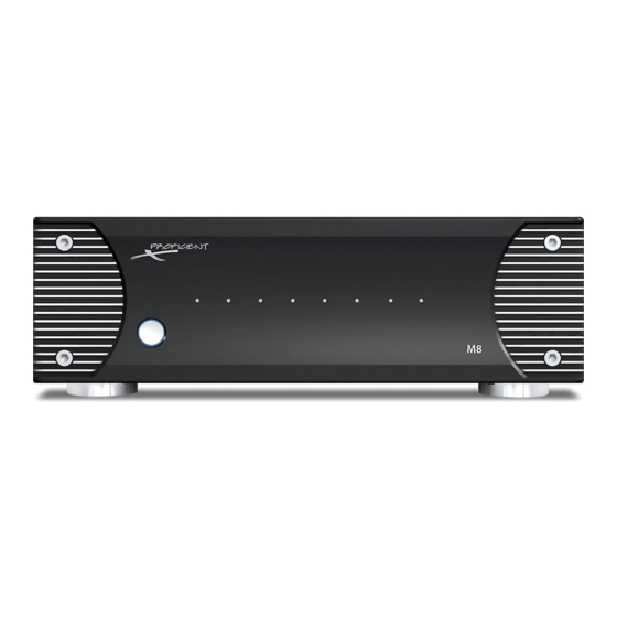
Simply turn on the A/V Receiver, play a source and music automatically plays throughout the entire house. The M8 is more than a solid performer, it looks good too. The cast aluminum Front Panel is like no other and makes an impressive addition to any stack of gear. -
Page 5: What's Included
FEATURES WHAT’S INCLUDED 1 - M8 Eight Channel Audio Amplifier 1 - Power Cord 1 - M8 Installation & User Guide M8 FEATURES Amplifier 35W Continuous @ 8Ω; 20Hz - 20kHz; <0.07% THD (2 Channels driven into 8 ohms - remainder at 1/8 of rated power) 55W Continuous @ 4Ω;... -
Page 6: Front Panel
FRONT PANEL 1. ON/OFF - Press this button to turn the M8 ON/OFF. (Rear Panel Power Mode switch set to ON.) When OFF, the button back- light is OFF. To turn the unit ON, press the button. The ON/OFF button backlight and all eight Front Panel LEDs will illuminate blue. -
Page 7: Rear Panel
A stereo source connected to BUS IN Left & Right will be fed to any M8 channel pair (1/2, 3/4, 5/6, 7/8) with the Channel Input switches set to BUS L and BUS R. A mono source connected to either the BUS L or BUS R IN can be fed to any channel by setting the Channel Input switch to BUS L or BUS R. - Page 8 13. 12V DC CONTROL OUT - (One 3.5mm mini jack) Connect to the 12V DC Control Input on a device that is to be synced to M8 ON/OFF status. When the M8 turns ON, (Manual, Auto ON or Trigger) the 12V DC Control Out will output 12 V DC that can be used to activate a DC voltage controlled device.
-
Page 9: Installation
Closed spaces such as equipment cabinets and racks can get hot with the heat generated by microprocessors and motors in vari- ous devices. Providing proper ventilation for good air flow will help keep the temperature down and protect not only the M8 but all system components and help preserve their longevity. -
Page 10: Speaker Placement
INSTALLATION Video Display Front Front Left Right A=B=C Ideal Listening Zone Diagram 4 Speaker Placement SPEAKER PLACEMENT Use the following recommendations when determining speaker placement. Determine The Ideal Listening Zone The area where the user will most likely be sitting when listening to the speakers is the Ideal Listening Zone. Placement of Stereo Speakers The distance between the left and right speakers should as closely equal the distance from one speaker to the listener as pos- sible. -
Page 11: Wire Requirements
Connecting the M8 for multiroom audio requires that two pair of speaker wire be run from the M8 location to each volume control in home runs (each run direct from the M8 to each volume control). One additional pair of speaker wires will then be run from each volume control to each of the speakers that will be controlled by that volume control. -
Page 12: Speaker Connections
CAUTION! Regardless of configuration follow the connection instructions for normal and bridged power carefully. Failure to Volume do so can cause severe damage to the M8 and speakers. The Control Proficient Warranty does not cover this type of damage. For example of normal power speaker connections, Channels 1 &... -
Page 13: Bridged Mode Speaker Connections
Normal Mode Speaker Connections. CAUTION! Regardless of configuration follow the connection instructions for normal and bridged power carefully. Failure to do so can cause severe damage to the M8 and speakers. The Proficient Warranty does not cover this type of damage. NO CONNECTION... -
Page 14: Connections & Setup
1. Using a mono RCA patch cable with gold ends, connect the line level audio OUT of a mono audio source to the BUS IN left or right input on the M8. 2. Set the Channel Input switches for the channels that are to output a source connected to BUS IN Left to BUS L. -
Page 15: Aux In
M8s. Also see: System Applications/Multiroom 1. Using a stereo patch cable with gold ends, connect the BUS LOOP on M8 #1 to the BUS IN on M8 #2. 2. Repeat Step 1 for all additional M8s. (Five M8s total.) 3. -
Page 16: Bridged Mode Connections
1. Using a stereo RCA patch cable with gold ends, connect the L & R line level audio OUT of an audio source to the odd number (1, 3, 5, 7) Line INs on the M8. Use channels 1, 5 for left, use channels 3, 7 for right. In Diagram 13, Channel 5 is left, Channel 7 is right. -
Page 17: Power On/Off Modes
OFF button backlight will tun ON (blue). After a few seconds the amplifier will output audio to properly connected channels. To turn OFF, cut the Control Out voltage from the trigger device. The M8 will turn OFF. (The ON/OFF button backlight will turn OFF.) If not, confirm trigger IN/OUT connections and polarity. -
Page 18: Control Out
CONNECTIONS & SETUp Control Out Power Mode Switch The M8 features a 12VDC Control Out that can be used to sync set to ON, Auto or Trigger an external device with a 12VDC Control IN to M8 power ON/OFF status. When the M8 turns ON (Manual, Audio Sense or Trigger) the Control Out will output 12VDC. -
Page 19: Level Control
In Diagram 20, (Bridged Mode), Channel 5 is left, Channel 7 is right. 4. Slowly raise the master volume on the receiver or zone controller until audio is playing through the M8 at a moderate level. -
Page 20: System Applications
Pro cient Pro cient VCS60 VCS60 VCS60 VCS60 Volume Volume Volume Volume Control Control Control Control Pro cient C645 Ceiling Speakers Pro cient C645 Ceiling Speakers Pro cient C645 Ceiling Speakers Pro cient C645 Ceiling Speakers Diagram 21 M8 Multiroom System... -
Page 21: Multiroom
Bus Loop The M8 BUS LOOP is a fixed line level audio output that can be used in a number of different ways. In the example shown, the BUS LOOP is being fed back to the M40 Receiver Main IN. The M40 features a pre-out/main in connection for various purposes. In this case, that connection will be used to insert the M8 into the source audio signal path. - Page 22 VCS60 VCS60 VCS60 Volume Volume Volume Volume Control Control Control Control Pro cient C645 Ceiling Speakers Pro cient C645 Ceiling Speakers Pro cient C645 Ceiling Speakers Pro cient C645 Ceiling Speakers Diagram 22 M8 Home Theater Plus Second Zone System...
-
Page 23: Home Theater Plus Second Zone
Bus In The M8 is connected to the M80 Receiver Zone 2 OUT. The Zone 2 OUT is a fixed line level audio output that is connected to the M8 BUS IN. The M8 BUS IN audio signal will output through any channel(s) that are set to BUS L (left) or BUS R (right). - Page 24 Zone 2 Zone 4 Room 1 Room 2 Pro cient Pro cient VCS60 VCS60 Volume Volume Control Control Pro cient C850 Ceiling Speakers Pro cient C645 Ceiling Speakers Pro cient C645 Ceiling Speakers Diagram 23 M8 Multizone Mixed Use Application...
-
Page 25: Multizone Mixed Use
Bridging Channels 5/6 and 7/8 creates a high power stereo output for Zone 4. Line In The M4 Zone 4 Pre-Out is connected to the M8 Bridged Channel 5/6 and 7/8 Line IN’s. The M4 Zone 4 audio signal will only output through the bridged channels. -
Page 26: Troubleshooting
TROUBLEShOOTINg PROBLEM SOLUTION Power Unit does not power up. a) Confirm Power Cord is plugged in to an unswitched 110V AC Outlet. b) If using audio sensing, confirm connection and audio output from audio source. Also confirm ON/OFF button is in the ON (in) position. -
Page 27: Specifications
SpECIFICATIONS Audio Sections Power Output/Channel (2 channels driven into 8 Ω; remainder @ 1/8 rated power) 35 Watts, 20Hz to 20kHz THD (at rated power) <0.07% Power/Channel (2 channels driven into 4 Ω) 55 Watts <0.1%THD @ 1kHz Power/Channel (bridged mode driven into 8 Ω) 110 Watts <0.5%THD @ 1kHz Damping Factor (non-bridged mode) >130, all channels... -
Page 28: Limited 2-Year Warranty
All replaced parts and product become the property of Proficient Audio Systems. The foregoing is your sole and exclusive remedy for breach of warranty. If the product is not found to be defective, Proficient will contact you to arrange for return of the product to you, at your expense. -
Page 29: Notes
NOTES... - Page 30 NOTES...
- Page 31 NOTES...
- Page 32 Audio Systems 940 Columbia Avenue, Riverside, CA 92507 877.888.9004 • Fax 951.750.6304 • proficientaudio.com ©2009 Proficient Audio Systems 1301-72800...
Need help?
Do you have a question about the M8 and is the answer not in the manual?
Questions and answers