
Related Manuals for Maktec MT370


Summary of Contents for Maktec MT370
- Page 1 Trimmer MODEL MT370 005430 I N S T R U C T I O N M A N U A L WARNING: For your personal safety, READ and UNDERSTAND before using. SAVE THESE INSTRUCTIONS FOR FUTURE REFERENCE.
-
Page 2: Specifications
SPECIFICATIONS Model MT370 Collet chuck capacity 6.35 mm (1/4”) or 6.0 mm 35,000 No load speed (min Overall length 199 mm Net weight 1.6 kg Safety class Class I • Due to our continuing programme of research and development, the specifications herein are subject to change without notice. -
Page 3: General Safety Rules
GENERAL SAFETY RULES ENA100-1 WARNING: Read all instructions. Failure to follow all instructions listed below may result in electric shock, fire and/or serious injury. The term “power tool” in all of the warnings listed below refers to your mains operated (corded) power tool or battery operated (cordless) power tool. -
Page 4: Additional Safety Rules
any other condition that may affect the power power tool, taking into account the working con- tools operation. If damaged, have the power tool ditions and the work to be performed. Use of the repaired before use. Many accidents are caused power tool for operations different from those by poorly maintained power tools. -
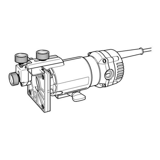
Page 5: Functional Description
FUNCTIONAL CAUTION: DESCRIPTION • Always be sure that the tool is switched off and unplugged before adjusting or checking function on the tool. Adjusting bit protrusion 005431 To adjust the bit protrusion, loosen the clamping screw and move the tool base up or down as desired. -
Page 6: Operation
OPERATION Set the tool base on the workpiece to be cut without the bit making any con- tact. Then turn the tool on and wait until the bit attains full speed. Move the tool forward over the workpiece surface, keeping the tool base flush and advancing smoothly until the cutting is complete. - Page 7 Remove the chip deflector. 004556 Loosen the screws and remove the base protector. Place the templet guide on the base and replace the base protector. Then secure the base protector by tightening the screws. 1. Screwdriver 2. Base protector 3. Screws Secure the templet to the workpiece.
- Page 8 Remove the chip deflector. 004559 Attach the straight guide with the clamp screw (A). Loosen the wing nut on the straight guide and adjust the distance between the bit and the straight guide. At the desired distance, tighten the wing nut securely. When cutting, move the tool with the straight guide flush with the side of the workpiece.
- Page 9 For cutting circles between 121 mm and 221 mm in radius. 001994 NOTE: • Circles between 172 mm and 186 mm in radius cannot be cut using this guide. 1. Wing nut 2. Wave washer 3. Flat washer 4. Guide plate 5.
-
Page 10: Maintenance
When cutting, move the tool with the guide roller riding the side of the work- 001998 piece. 1. Workpiece 2. Bit 3. Guide roller MAINTENANCE CAUTION: • Always be sure that the tool is switched off and unplugged before attempting to perform inspection or maintenance. Replacing carbon brushes 001145 Remove and check the carbon brushes regularly. - Page 11 ACCESSORIES Router bits Straight bit 005116 C00157 1/4” 1/4” 1/4” “U”Grooving bit 005117 C00158 1/4” “V”Grooving bit 005118 C00123 θ 90° 1/4” Drill point flush trimming bit 005120 C00159 1/4”...
- Page 12 Drill point double flush trimming bit 005121 C00160 1/4” Corner rounding bit 005125 C00161 1/4” 1/4” Chamfering bit 005126 C00131 θ 30° 30° 30° E 1/4” 45° 45° 45° E 1/4” 60° 60° 60° E 1/4” Cove beading bit 005129 C00133 1/4”...
- Page 13 Ball bearing corner rounding bit 005131 C00135 1/4” 1/4” Ball bearing chamfering bit 005132 C00136 θ 45° 45° 45° E 1/4” 60° 60° 60° E 1/4” Ball bearing beading bit 005133 C00137 1/4” 1/4” Ball bearing cove beading bit 005134 C00138 1/4”...
- Page 14 Memo...
- Page 15 Memo...
- Page 16 Makita Corporation 884536A5...
Need help?
Do you have a question about the MT370 and is the answer not in the manual?
Questions and answers