
Subscribe to Our Youtube Channel
Related Manuals for Quantum Composers 9730 Series


Summary of Contents for Quantum Composers 9730 Series
- Page 1 9730 Series Pulse Generator Operating Manual Version 1.2 Your distributor: Quantum Composers, INC 212 Discovery Drive Bozeman, MT 59718 Phone: (406)582-0227 Fax: (406)582-0237 www.quantumcomposers.com...
-
Page 2: Table Of Contents
1 Table of Contents 1 TABLE OF CONTENTS ........................1-2 2 INTRODUCTION ..........................2-5 ..........................2-5 ECHNICAL UPPORT ............................. 2-5 ARRANTY ..........................2-5 ACKAGE ONTENTS 3 SAFETY ISSUES............................ 3-6 4 PRODUCT OVERVIEW ........................4-7 Key Features ............................4-7 Advanced Features/Options ....................... 4-7 5 PULSE GENERATOR CONCEPTS AND OPERATION .............. - Page 3 – I ............9-23 UICK TART NTERNAL INGLE ENERATOR PERATION Pulse Width, Delay........................... 9-23 Amplitude ............................9-23 Enable .............................. 9-23 Interlock ............................9-23 Wait for Charge ..........................9-23 ARM Key Switch ..........................9-23 Start ..............................9-23 – S ............9-24 UICK TART INGLE...
- Page 4 ........................... 10-40 PECIAL OMMANDS APPENDIX A - SPECIFICATIONS ......................... A-1 APPENDIX B - SAFETY SYMBOLS ........................B-1 ........................B-1 AFETY ARKING YMBOLS...
-
Page 5: Introduction
2 Introduction This manual is designed to familiarize you with the Quantum Composers 9730 series pulse generator and is arranged so that you can easily find the information for which you are looking. Generally, each topic has its own section and no section assumes that your have read anything else in the manual. -
Page 6: Safety Issues
3 Safety Issues Normal use of equipment exposes users to a certain amount of danger from electrical shock because testing must be performed where exposed voltage is present. An electrical shock causing 10 milliamps of current to pass through the heart will stop most human heartbeats. -
Page 7: Product Overview
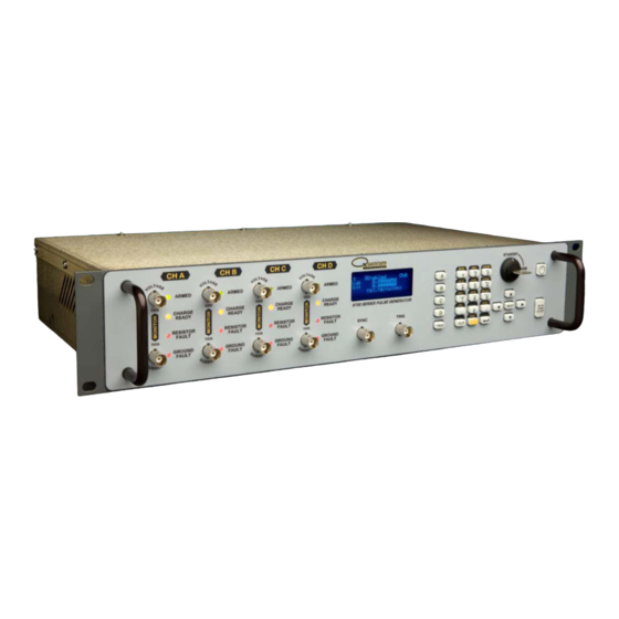
4 Product Overview The 9730 series combines industry leading QC digital delay methodologies along with high capacity charge banks to generate precisely timed adjustable amplitude current pulses. This ability to generate highly precise current pulses makes this unit ideal for applications that require a high level of accuracy and repeatability. -
Page 8: Pulse Generator Concepts And Operation
5 Pulse Generator Concepts and Operation System Timer Functions • Burst Mode The System Timer functions as a non-retriggerable, multi-vibrator T pulse generator in ‘Burst’ mode. This means that once started the timer will produce pulses continuously at the specified rate until the highest channel burst count... - Page 9 Menus may include a number of different pages, with each page containing up to four adjustable parameters or state variables. The status block in the upper-left corner of the display shows a vertical arrow if the current menu contains additional pages. To select the next page, press the channel button again or select the same menu pressing the FUNC key and the channel/menu key again.
- Page 10 o 7 => P Q R S p q r s 7 o 8 => T U V t u v 8 o 9 => W X Y Z w x y z 9 o 0 => 0 1 2 3 4 5 6 7 8 9 o .
-
Page 11: Front Panel Overview
6 Front Panel Overview 9730 Display Display Layout and Indicators A graphical display module displays parameters and status information. The status information is located in the upper-left corner of the display, between the two brackets. There are three enunciators: Vertical Arrow Indicates there are additional pages to the current Menu. -
Page 12: Second Level Menus (Function Key)
and left arrows (referred to as LEFT and RIGHT keys for the rest of this document) move the cursor to different positions within the current parameter. The NEXT key selects the next parameter in the currently displayed menu. • Numeric Keypad Allows numbers and alphanumeric values to be entered. -
Page 13: Arm Switch (Keyed)
• ARMED Green LED indicating the channel is armed and ready. • CHARGE READY Amber LED indicating the channel capacitor bank is charged and ready. • RESISTOR FAULT Red LED indicating the pre test error status of the current channel. •... -
Page 14: Rear Panel Overview
7 Rear Panel Overview Description of Rear Panel Area Channel Connections (Banana Jacks) Each channel has two sets of banana jacks for connecting to the device under test: • OUTPUT Red and Black current jacks (labeled ‘A’ between them) connect to the positive and negative drive terminals (respectively) of the device under test. -
Page 15: Cooling Fans
Cooling Fans The rear panel also contains one or two cooling fan outputs depending on whether the instrument has two or four channels respectively. Air is circulated in through the rear panel and out through the side panel openings. WARNING: DO NOT BLOCK COOLING FAN INPUTS OR OUTPUT(S). -
Page 16: Menu Structure
8 Menu Structure MODE Menu (FUNC + 1) • Page0 o Line0 – empty o Line1 – Mode: Single Shot, Burst o Line2 – empty o Line3 – empty Setting System Mode Parameters Mode: Selects the T mode: Single Shot or Burst mode. Note: When Trigger is enabled while in Burst mode, burst mode is disabled and the unit will perform as in Single Shot mode. -
Page 17: Channel Menu (A, B, C, Or D)
Channel Menu (A, B, C, or D) • Page0 o Line0 – Channel: Enabled, Disabled o Line1 – Wid: <width> o Line2 – Dly: <delay> o Line3 – decimal place indicator • Page1 o Line0 – ‘Enable’ Enabled, Disabled o Line1 – empty o Line2 –... -
Page 18: Channel Test Menu (Func + A, B, C, Or D)
Channel Test Menu (FUNC + A, B, C, or D) • Page0 o Line0 – empty o Line1 – PreTest: Disabled o Line2 – empty o Line3 – empty • Page0 – Alt o Line0 – empty o Line1 – PreTest: Enabled o Line2 –... - Page 19 o Line3 – IPstMax: <maximum test current> Setting Channel Post-Test Parameters PstTest: Enables or disables post resistance test and requirements for the channel. PstMeas: Displays the measured resistance from the last run post-test. TstType: Sets the type of test for determining pass/fail condition of the Post Test.
-
Page 20: Trig Menu (Trig)
TRIG Menu (TRIG) • Page0 o Line0 – empty o Line1 – Mode: Disabled o Line2 – empty o Line3 – empty • Page0 – Alt o Line0 – empty o Line1 – Mode: Enabled o Line2 – Level: <trigger threshold level> o Line3 –... -
Page 21: System Menu (Func + 3)
CLR: Pressing the CLR while in the Counter menu will reset the Counts value to 0. SYSTEM Menu (FUNC + 3) • Page0 o Line0 – empty o Line1 – Front Sync: Disabled, T0, ChA, ChB, (ChC, ChD) o Line2 – Rear Sync: Disabled, T0, ChA, ChB, (ChC, ChD) o Line3 –... -
Page 22: Store Menu (Func + 6)
Front Sync: Sets the source of the front panel sync output signal set to the front panel. Choices are Disabled, T , ChA, and ChB for two channel instruments, with ChC and ChD added for four channel instruments. Rear Sync: Sets the source of the rear panel sync output signal set to the front panel. -
Page 23: Operating Instructions
9 Operating Instructions Quick Start – Internal Single Shot Generator Operation Although the 9730 has a powerful set of feature extensions that allow the user to cater it to many unique test setups, the following steps may be followed to quickly generate a single shot internally generated pulse. -
Page 24: Quick Start - Single Shot External Trigger Operation
Quick Start – Single Shot External Trigger Operation To generate a single pulse for single external trigger event, based on the default configuration 0, the following parameters need to be set: Trig Enter the trigger menu by pressing the TRIG key. Change mode to ‘Enabled’. -
Page 25: Wait For Charge
Wait for Charge When the Safety Interlock is properly shorted the instrument will charge up the capacitor banks for each channel (regardless of whether the channel is enabled or not). When the channel ‘CHARGE READY’ LEDs become illuminated, proceed to the next step. ARM Key Switch Turn the Arm Key Switch... -
Page 26: External Input Overview
specified in the RATE menu. The minimum period will be limited to 5 times the largest set pulse width. Pressing the RUN/STOP button while the burst is in process will stop the output. After the burst has been completed, pressing the RUN/STOP button will generate another burst. -
Page 27: Single Shot Mode (Trigger Enabled)
width. This allows for filtering out of errant or “runt” pulses that may be caused by noisy environments. Single Shot Mode (Trigger Enabled) The external trigger input triggers a single pulse for each enabled channel. External triggering is internally limited to 5 times the maximum set pulse width. To generate channel pulses in single shot mode with the trigger enabled: •... -
Page 28: Post Pulse Resistance Testing
• Turn Arm Switch to ‘ARM’ Position. • Press the FUNC key and then the PRE key (‘.’ on the numeric keypad) to run the pre pulse resistance test. • Refer to Testing Mode Error Conditions for more information on any resulting errors. - Page 29 • Error - “Valid Pre-Test Required” – This message is displayed or returned through a channel error query when the instrument has attempted to trigger and one or more channels with pre pulse resistance testing enabled have not yet passed testing. o Simultaneous flashing of the ‘RESISTOR FAULT’...
-
Page 30: 10 Programming The 9730
10 Programming the 9730 Personal Computer to Pulse Generator Communication The 9730 comes standard with a RS232 serial and USB interface. An Ethernet interface is available as an option. All menu settings can be set and retrieved over the computer interface using a simple command language. The command set is structured to be consistent with the Standard Commands for Programmable Instruments (SCPI). -
Page 31: Usb Interface Overview
The USB interface is standard on the 9730. Before this type of communication can be used, the appropriate drivers must be installed on the personal computer. These drivers are included on the disc that was shipped with your unit. Please contact Quantum Composers or visit www.quantumcomposers.com for updated installation files and instructions. -
Page 32: Ethernet Interface Overview
• If a mapped COM port is the desired communication method, the Digi Connectware’s “Realport Drivers” setup must be used to install the COM port on your computer. Please refer to the Digi Connectware documentation supplied on the disc, or call Quantum Composers technical support. Programming Command Types and Format The 9730 Pulse Generator uses two types of programming commands: IEEE 488.2 Common Commands and Standard Commands for Programmable... -
Page 33: Ieee 488.2 Common Command Format
When the pulse generator responds to a command, whether it is a query or a parameter change, it also appends its return strings with these characters. Coded applications could use the behavior to know when to stop reading from the unit. However, if the “echo” parameter is enabled, there will be two sets of line terminators, one following the echoed command string, and the one following the pulse generator’s response. -
Page 34: Scpi Optional Keywords
Selects from a finite number of predefined strings. Legacy Command Support In addition to IEEE 488.2 and SCPI formatted commands, the 9730 Series also supports all legacy 971x commands for ease of software migration from the 971x instruments. Legacy commands begins with a ‘$’ symbol with each command keyword separated by a ‘:’... -
Page 35: Programming Examples
Programming Examples Example 1: 20 ms pulsewidth, 2.3 ms delay, internal trigger, single shot operation. :PULSE0:MODE SING<cr><lf> sets system mode to single shot :PULSE0:TRIG:MODE DIS<cr><lf> disables the external trigger :PULSE1:WIDT 0.020<cr><lf> sets pulsewidth to 20 ms :PULSE1:DELAY 0.0023<cr><lf> sets delay to 2.3 ms :PULSE1:STATE ON<cr><lf>... -
Page 36: 9730 Scpi Command Summary
9730 SCPI Command Summary Instrument Commands Keyword Parameter Comments :INSTrument Subsystem :CATalog Query only. Returns a comma-separated list of the identifier strings for all channels. A two channel instrument would return: T , CHA, CHB. :FULL Query only. Returns a comma-separated list of the identifier strings of all channels and their associated number. -
Page 37: System Pulse Commands
System Pulse Commands Keyword Parameter Comments :SPULse or Subsystem. Contains commands to control the output PULSe[0] pulse generation. Commands without suffix refer to the currently selected logical instrument. See INSTrument subsystem. :STATe <boolean value> Enables / Disables the output for all channels. Command is the same as pressing the RUN/STOP button. -
Page 38: Channel Commands
Channel Commands Keyword Parameter Comments :PULSe<n> Subsystem. Contains commands to control the output pulse generation. Valid suffix values depends on the number of channels (ChA = 1, ChB = 2, etc). Command without suffix refers to the currently selected logical instrument. -
Page 39: Display Commands
Display Commands Keyword Parameter Comments :DISPlay Subsystem. Contains commands to control the display. :MODe <boolean value> Enables/Disables automatic display update. When true, front panel display is updated with serial command parameter changes. Setting to false decreases response time. :UPDate Query only. Forces update of display. Use when mode is false. -
Page 40: Ieee 488.2 Common Commands
IEEE 488.2 Common Commands Mnemonic Command Name Parameters Comments Identification Query Queries the Pulse Generator *IDN? Identification. The ID will be in the following format: model#,serial#,version# Command list Query Query: Returns an indented list *CAT? of all SCPI commands. Label Command/Query <string value>... - Page 41 Some customers have started using the 9730 device in high throughput production lines and have requested that this safety feature be removed. Quantum Composers has added a bypass feature to accommodate these customers under the condition that usage of...
-
Page 42: Appendix A - Specifications
Appendix A - Specifications UNIT I/O Configuration Output Modules Output Modes Single & Burst Control Modes Internal Rate & External Trigger Internal Rate Generator Rate 0.01 40,000 Resolution Accuracy Jitter ns(RMS) External Trigger Inputs Triggers Front & Rear Rate **** Longest Pulse Insertion Delay... - Page 43 Output Amplitude Resolution Accuracy * +/-0.5 +/-2 Rise Time * Overshoot * Slew Rate * 0.15 A/us Compliance Voltage Burst Count Bursts Monitors Current Scale Voltage Scale Accuracy +/-1.0 +/-2.5 Bandwidth 1000 Propagation Delay Offset Resistance Measurement Ω Range Ω Resolution Accuracy .1 to 15Ω...
- Page 44 Communications RS232 4800 115200 115200 Baud Serial Bridge Ethernet Optional Size Rack Mount 19" x 10" 2U size rack mount Electrical AC Input Voltage AC Input Frequency AC Power 2Ch AC Power 4Ch * See data plots for more details. All Output data was taken with 50ft and 2ft of cable with 1 ohm of load resistance unless otherwise specified.
- Page 45 Legend: Yellow – Current Probe Measurement Blue – Voltage Monitor Measurement Red – Current Monitor Measurement Yellow –.1V/A 6A @ .1 scale = 600mV Blue –.2V/V 1 Ohm @ 6A & .2 scale = 1.2V Red –.5V/A 6A @ .5 scale = 3V The output monitors are optically isollated and can have 1us to 3us of transmision delay, see Figure 2.
- Page 47 The output circuitry is designed to handle 30W of power and is firmware limited to prevent overdriving the output circuitry. Figure 12 shows the maximum settable pulse width and minimum settable period at max pulse width. The minimum period is set to 5 times the set pulse width until it reaches the longest settable period of 200s.
-
Page 48: Table Of Contents
Appendix B - Safety Symbols Safety Marking Symbols Technical specifications including electrical ratings and weight are included within the manual. See the Table of Contents to locate the specifications and other product information. The following classifications are standard across all QC products: •...
Need help?
Do you have a question about the 9730 Series and is the answer not in the manual?
Questions and answers