Table of Contents
Advertisement
The Local Exhaust & Ventilation Company Inc.
22-1050 Brock Rd, Pickering, Ontario L1W 3X4
Tel: 905.831.7001 Fax: 905.831-7443
Toll Free: 1.888.862.5356
E-mail: sales@lev-co.com Web Site: www.lev-co.com
OWNERS MANUAL
MODEL V410
(INCLUDES VIBRAPULSE CLEANING SYSTEM*)
INTRODUCTION
SPECIFICATIONS
UNPACKING
INSTALLATION
MOUNTING
ELECTRICAL
OPERATION
MAINTENANCE
TROUBLESHOOTING
REPLACEMENT PARTS
MOTOR TROUBLE GUIDE
***IMPORTANT***
THIS MANUAL CONTAINS PRECAUTIONARY STATEMENTS RELATING TO WORKER SAFETY.
READ AND
SAVE THIS MANUAL COMPLETELY AND COMPLY AS DIRECTED.
ALL THE POTENTIAL HAZARDS OF DUST
AND MIST CONTROL SYSTEMS AND EQUIPMENT ARE IMPOSSIBLE TO LIST; THEREFORE, OBTAIN THE
SERVICES OF A PROFESSIONAL INSTALLER.
A FIRE PROTECTION EXPERT SHOULD BE OBTAINED IN THE
EVENT THE PRODUCT IS INTENDED FOR USES WHICH PRESENT A POTENTIAL RISK OF FIRE OR FIRE
PROPAGATION. REFER TO APPROPRIATE AUTHORITIES, AND DISCUSS YOUR INTENDED USE WITH YOUR
LOCAL DISTRIBUTOR OR AIRFLOW SYSTEMS, INC.
WORKERS HANDLING EQUIPMENT OR SYSTEMS
SHOULD BE INSTRUCTED TO CONDUCT THEMSELVES IN A SAFE MANNER.
PART # 4KT11067
(REV 4/99/-/#32-2142)
*PATENT APPLIED FOR
3
Advertisement
Chapters
Table of Contents

Summary of Contents for Airflow Systems V410
- Page 1 EVENT THE PRODUCT IS INTENDED FOR USES WHICH PRESENT A POTENTIAL RISK OF FIRE OR FIRE PROPAGATION. REFER TO APPROPRIATE AUTHORITIES, AND DISCUSS YOUR INTENDED USE WITH YOUR LOCAL DISTRIBUTOR OR AIRFLOW SYSTEMS, INC. WORKERS HANDLING EQUIPMENT OR SYSTEMS SHOULD BE INSTRUCTED TO CONDUCT THEMSELVES IN A SAFE MANNER.
- Page 2 ALWAYS USE AIRFLOW SYSTEMS, INC. REPLACEMENT PARTS AND FILTERS TO MAINTAIN WARRANTY. TO ORDER SPARE PARTS CONTACT: The Local Exhaust & Ventilation Company Inc. 22–1050 Brock Rd, Pickering, Ontario L1W 3X4 Tel: 905.831.7001 Fax: 905.831.7443 Toll Free: 1.888.862.5356 E-mail: sales@lev-co.com Web Site: www.lev-co.com...
-
Page 3: Table Of Contents
TABLE OF CONTENTS 1. Safety..........................4 2. Airflow Systems Sets the Standard ................5 3. Specifications ........................6 4. Inspection ........................7 5. Preparation and Installation ..................7 6. Compressed Air Supply ....................7 7. Vibra Pulse Filter Cleaning System................7 8. -
Page 4: Safety
READ THIS MANUAL CAREFULLY BEFORE ATTEMPTING TO INSTALL OR OPERATE THE MODEL V410 UNIT. RETAIN THESE INSTRUCTIONS FOR FUTURE REFERENCE. SAFETY RULES Follow all electrical and safety codes as well as the National Electrical Code (NEC), National Fire Protection Association (NFPA), and the Occupational Safety and Health Act (OSHA). All electrical connections and wiring should be performed by qualified personnel only. -
Page 5: Airflow Systems Sets The Standard
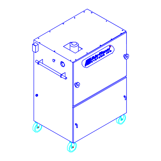
(2 swivel, 2 fixed). It comes standard with (2) 3” FPT couplings for attachment of collection hoses. The Model V410 can be mounted in a stationary location if desired by ordering it with the optional hopper and stand kit. - Page 6 Figure 1.
-
Page 7: Specifications
SPECIFICATIONS(*): MODEL V410 STD DIM: 36" W x 26" D x 53" H [0.91m W x 0.66m D x 1.35m H] WEIGHT: 680 lb. (STD) [309 kg] CONSTRUCTION: 12 gauge welded zinc coated steel cabinet, finished with a two part chemical and oil resistant paint. -
Page 8: Inspection
1” hose clamp. Refer to Figure 3. Use any standard Quick Disconnect 3/8” fitting (as used on an air tool) to attach to the supply air. The V410 unit comes with 10’ of 3/8” air line. If a... -
Page 9: Electrical
TROUBLESHOOTING Section in this manual. ELECTRICAL All 3 phase AC Model V410 units have wiring terminated inside the junction box located on the side of the unit. Motor starters and disconnects are not supplied with the unit (unless purchased as an option), and must meet local and National Electrical Code. -
Page 10: Operation
OPERATION Operation of the Model V410 is very straight forward. Roll the unit to the desired work area and arrange it so that no equipment will come into contact with the unit. Simply switch the unit ON when smoke or dust collection is required. -
Page 11: Maintenance
ASSEMBLIES. LOCK OUT DISCONNECTS TO PREVENT UNEXPECTED APPLICATION OF POWER. The Model V410 comes standard with (2) CLEAN 2 filter cartridges of 150 square feet of media each. An optional External Module is available for a final filter. This external module can house either a HEPA filter or an adsorption bank (AD). - Page 12 1 - Hose (2VP2-1012), quantity as required by applicable unit (1 hose per cartridge). Figure 7. 7. Remove the old Vibra Pulse hose. This is done by loosening the hose clamp securing the spring at the top of the VP hose where the VP hose attaches to the 3/8” hose barb. Slide the spring and hose clamp down the VP hose and set aside for later use.
- Page 13 9. Install the new Vibra Pulse hose onto the air cleaner’s hose barb until fully seated against brass hex on barb, see Figure 9. Lubricate with Figure 8. water or Windex to ease installation. Do not use oil or grease as lubricant! Figure 9.
-
Page 14: Filter Service
A Material Safety Data Sheet (MSDS) will be furnished upon request. Please contact the Airflow Systems Representative or the AFS Factory. Filter service is required when a reduction of airflow (suction) is observed. The optional pressure gauge is used to judge the amount of particulate collected on the filter. -
Page 15: Filter Replacement/Removal For Cleaning
FILTER REPLACEMENT/ REMOVAL FOR CLEANING 1. Turn unit OFF and disconnect from power source. 2. Remove filter access panel. 3. Release filter retaining latch located between cartridges, (see Figure 11.) This will lower the filter holding frame. Unhook latch to let holding frame rest at lowest position. 4. -
Page 16: Hepa Filters
IT IS IMPORTANT TO USE ONLY CLEAN AND DRY COMPRESSED AIR TO CLEAN THE FILTERS, OTHERWISE CONTAMINATION TO CARTRIDGE FILTER ELEMENT WILL RESULT. DO NOT HOOK UP TO A COMPRESSED AIR LINE THAT HAS AN AUTOMATIC OILING DEVICE ON IT. OIL OR WATER WILL MAKE CLEANING DIFFICULT AND SHORTEN THE FILTER LIFE. -
Page 17: Other Service
OTHER SERVICE Most other components of your Model V410 air cleaner require little or no routine servicing. Items such as motor/blower, tubing, and gaskets should be checked twice a year under normal usage; more frequently under severe 24-hour-per-day usage. Clean, repair, or replace parts as necessary. Replacement parts are available from your Airflow Systems distributor. -
Page 18: Replacement Parts
REPLACEMENT PARTS The following section lists typical replacement parts for the Model V410 . If a part is not listed in Table 2, contact your local Airflow Systems Representative or the AFS Factory. Refer to Figures 14 and 15 for parts illustrations. - Page 19 Figure 14. Model V410 filter lifting assembly. Figure 15.
-
Page 20: Troubleshooting
The troubleshooting guide included in this manual is for qualified personnel only. A Motor Trouble Guide is included in Appendix A. If the unit does not function properly after following the guidelines in this manual, consult an Airflow Systems Representative for further help. PROBLEM... -
Page 21: Notes
MOTOR VOLTAGE (MEASURED): MOTOR CURRENT (MEASURED): MOTOR FLA (FROM NAMEPLATE): MOTOR VOLTAGE (FROM NAMEPLATE): ALWAYS USE AIRFLOW SYSTEMS REPLACEMENT PARTS AND FILTERS TO MAINTAIN WARRANTY TO ORDER SPARE PARTS CONTACT: The Local Exhaust & Ventilation Company Inc. 22–1050 Brock Rd, Pickering, Ontario L1W 3X4 Tel: 905.831.7001 Fax: 905.831.7443... -
Page 22: Appendix
APPENDIX 1. BRANCH WIRING ................A1 2. MOTOR TROUBLE GUIDE ..............A2 3. TYPICAL INSTALLATION WIRING DIAGRAM ........ A3 4. 4KT11096 - OWNERS MANUAL ADDENDUM – OPTIONAL AUTO- CLEAN CONTROLLER SYSTEM............A4 5. OWNERS MANUAL ADDENDUM – STATIC PRESSURE RELIEF VALVE .................... - Page 23 MOTOR WIRING GUIDE (BRANCH CIRCUIT) WIRING To connect motor for proper voltage and rotation, refer to connection diagram on nameplate or inside terminal/conduit box. If power factor correction capacitors are used for individual motor power factor correction, do not exceed maximum recommended value.
- Page 24 115V 230V 115V 230V 115V 230V 115V 230V 115V 230V 14(16) 14(18) 14(18)* 14(16) 14(16) 14(18) 14(18)* 14(16) 14(18) 14(18)* 14(18) 14(16)* 14(18) 14(16)* 14(18) 14(16) 1½ 14(16) [*] Type S, SO, SJ, SJO, etc. flexible cable wire sizes. See NEC Article 400 for ampacity. Above wire sizes based on approximate 5% voltage drop during starting;...
- Page 25 poor connections. 3. Load too high. 3. Check load motor is carrying at start -replace with larger motor. MOTOR 1. Excess Loading; high 1. Reduce load. Increase TAKES TOO inertia load. motor size. LONG TO 2. Inadequate wiring. 2. Increase wire size. Check for ACCELERATE poor connections.
- Page 26 TYPICAL INSTALLATION WIRING DIAGRAM...
- Page 27 PRODUCT IS INTENDED FOR USES WHICH PRESENT A POTENTIAL RISK OF FIRE OR FIRE PROPAGATION. REFER TO APPROPRIATE AUTHORITIES, AND DISCUSS YOUR INTENDED USE WITH YOUR LOCAL DISTRIBUTOR OR AIRFLOW SYSTEMS, INC. WORKERS HANDLING EQUIPMENT OR SYSTEMS SHOULD BE INSTRUCTED TO CONDUCT THEMSELVES IN A SAFE MANNER.
- Page 28 PART# 4KT1-1096 (REV 11/98/A/#26-1894)
- Page 30 ALWAYS USE AIRFLOW SYSTEMS, INC. REPLACEMENT PARTS AND FILTERS TO MAINTAIN WARRANTY. TO ORDER SPARE PARTS CONTACT: The Local Exhaust & Ventilation Company Inc. 22–1050 Brock Rd, Pickering, Ontario L1W 3X4 Tel: 905.831.7001 Fax: 905.831.7443 Toll Free: 1.888.862.5356 E-mail: sales@lev-co.com Web Site: www.lev-co.com...
- Page 31 TABLE OF CONTENTS 1. Safety......................... 4 2. Airflow Systems Sets the Standard ................4 3. Specifications ......................4 Electrical......................4 4. Inspection ........................4 5. Preparation and Installation ..................5 6. Electrical........................5 Single phase....................... 6 Three phase ....................... 7 7.
-
Page 33: Safety
Owners Manual are in effect after installation of the AUTOCLEAN system. As with all electrical devices, it should only be serviced by a qualified electrical technician. AIRFLOW SYSTEMS SETS THE STANDARD The AUTOCLEAN filter cleaning control system automatically controls off line cleaning of the filters in the equipment. -
Page 34: Preparation And Installation
PREPARATION AND INSTALLATION Through out this manual certain NOTES, CAUTIONS and WARNINGS are used. They are defined as: Note: Used to indicate an instruction that will make a particular task simpler or easier. CAUTION: Used when a process or item may cause damage to the equipment or system. WARNING: This term is used when personal injury or death is possible. -
Page 37: Single Phase
SINGLE PHASE CONNECTION The factory installed AUTOCLEAN control requires a minimum of field wiring in order to operate. All 115 VAC units with factory installed unit ON/OFF power switch are wired and require no further electrical wiring other than connection input to the power. Figure 1 illustrates the electrical connections for a 115 VAC single phase unit with a single cartridge. -
Page 38: Three Phase
THREE PHASE CONNECTION Three phase connections require the use of a manual or magnetic motor starter to allow the AUTOCLEAN system to operate off-line. The main power leads, L1, L2, L3 are not usually differentiated by color. The transformer power can be drawn from any two of these input power wires. NOTE: The voltage from one lead to neutral or ground is not the same as phase to phase. - Page 39 Figure 5. (Dual Cartridge with Relay) Figure 6. (Dual Cartridge without Relay)
- Page 41 Figure 7. (DT-3000 with Relay) Figure 8. (DT-3000 without Relay)
-
Page 44: Autoclean Unit Operation
AUTOCLEAN UNIT OPERATION When wired as shown above, the AUTOCLEAN control will sense operation of the air cleaner fan motor. When the motor is turned ON, the AUTOCLEAN patiently waits for when the motor is turned OFF. When OFF occurs, the AUTOCLEAN will wait for a time to clean. This time is adjustable from 0 to approximately 10 minutes. -
Page 47: Maintenance
Vibra-Pulse system. REPLACEMENT PARTS Listed below are common replacement parts for the AUTOCLEAN controller system. Check nameplate for actual voltage used. Consult with a local Airflow Systems Representative for ordering replacement parts. ITEM PART # DESCRIPTION... - Page 50 The Local Exhaust & Ventilation Company Inc. 22-1050 Brock Rd, Pickering, Ontario L1W 3X4 Tel: 905.831.7001 Fax: 905.831-7443 Toll Free: 1.888.862.5356 E-mail: sales@lev-co.com Web Site: www.lev-co.com OWNERS MANUAL ADDENDUM LATEST VERSION OF THE CLEAN AIR PLENUM WHICH INCLUDES THE STATIC PRESSURE RELIEF VALVE...
Need help?
Do you have a question about the V410 and is the answer not in the manual?
Questions and answers