
Related Manuals for Unitek DVR-404

Summary of Contents for Unitek DVR-404
- Page 1 User Guide Manual DVR-404/408/416 * Default system password: 111111 (for RAMS, Record stop, Menu setup, System off, Auto key lock) * Default ID: admin (for RAMS)
-
Page 2: Table Of Contents
Table of contents SYSTEM OVERVIEWS ............10 ..........................10 AFETY & O ...................... 12 OMPONENTS PTION 1.2.1 Components......................... 12 1.2.2 Options ..........................12 & ....................13 EATURES SPECIFICATIONS 1.3.1 Features ..........................13 1.3.2 Specifications ........................14 & ..................15 FUNCTION CONNECTIONS 1.4.1 Front view ........................... - Page 3 2.5.2 Recording modes......................... 29 ........................... 29 LAYBACK 2.6.1 Press the Play button ......................29 2.6.2 Audio files........................... 29 ..........................29 EARCH 2.7.1 Search mode ........................29 2.7.2 Search method ........................29 ..........................30 ACKUP 2.8.1 DVD-RW..........................30 2.8.2 USB flash memory Stick ..................... 30 ........................
- Page 4 3.2.1 Resolution ........................... 38 3.2.2 Audio Sync.......................... 38 3.2.3 Channel number ........................38 3.2.4 Quality..........................38 3.2.5 Frame rate..........................39 3.2.6 Record mode ........................39 3.2.7 Record Schedule Setup......................40 ......................41 VENT ETUP 3.3.1 Motion Detection Setting ....................41 3.3.1.1 Channel ...............................
- Page 5 3.6.2 Remote Connection Login Password .................. 50 3.6.3 Network Type ........................51 3.6.3.1 STATIC ............................... 51 3.6.3.2 DDNS Link On/off ..........................52 3.6.3.3 Port..............................52 3.6.3.4 IP Address ............................52 3.6.3.5 Subnet Mask ............................52 3.6.3.6 Gateway .............................. 52 3.6.4 DHCP..............................
- Page 6 3.7.8 Factory Default........................62 3.7.9 Software Upgrade........................ 63 ..........................63 ACKUP 3.8.1 Backup Device ........................64 3.8.2 Start Time ..........................64 3.8.3 End Time ..........................64 3.8.4 Channel ..........................64 3.8.5 Event ........................... 64 3.8.6 Backup Start ........................64 3.8.7 Format ..........................
- Page 7 3.12.1.1 Method of playback ..........................69 3.12.1.2 Screen of played back......................... 70 3.12.1.3 Control during playback........................70 3.12.2 Playback of still image ......................71 3.12.2.1 Method of playback ..........................71 3.12.2.2 Screen of playing back........................71 3.12.2.3 Control during Still Image Play back ....................72 3.13 .......................
- Page 8 4.3.17 Check the program version....................90 4.3.18 S/W upgrade of DVR ......................91 4.3.19 Program minimizing......................92 4.3.20 Close program ........................92 _RT ........................92 LAYER 4.4.1 Screen and button ........................ 92 4.4.2 Directory search ........................93 4.4.3 Search of still image..........................94 4.4.4 Calendar search...........................
- Page 9 ....................114 ERMINAL NFORMATION 5.2.1 DSUB-9P (RS-232)......................114 5.2.2 DSUB-25P ( AUX / ALARM / SENSOR) .................115 ....................116 ACTORY EFAULT ALUE 5.3.1 Main Menu .........................116 5.3.2 Search Menu........................121 ......................... 122 ROTOCOL 5.4.1 Code table.......................... 122 5.4.2 Usage..........................123 , FPS, HDD ............
-
Page 10: System Overviews
1. SYSTEM OVERVIEWS 1.1 Safety Please follow this instruction to prevent any kind of damage or loss. WARNING If you do not follow this instruction, it might bring severe damage or loss. The symbol is intended to alert the user to the presence of important operating and maintenance (servicing) instructions in the literature accompanying the unit. -
Page 11: Safety Instructions
Caution – Danger of explosion, if battery is incorrectly replaced. Replace only with the same or equivalent type. Warranty will be made void if the product is disassembled or manipulated by the user. Safety Instructions 1) Read these instructions. 2) Keep these instructions. 3) Heed all warnings. -
Page 12: Components & Option
1.2 Components & Option The following items are included with the 4, 8 & 16 Channel DVR. Please be certain that all items are included as soon as you open the box: 1.2.1 Components DVR (DVD-COMBO is installed as a basic equipment) Power cable DSUB-25 connector for AUX / ALARM / SENSOR. -
Page 13: Features & Specifications
1.3 Features & specifications 1.3.1 Features Real time 4/8/16 channel Standalone Digital Video Recorder Real time Recording & Playback 4CH : Full D1 Real Time(NTSC : 120 FPS, PAL : 100 FPS) 8CH : HALF D1 Real Time(NTSC : 240 FPS, PAL : 200 FPS) 16CH : CIF REAL TIME(NTSC : 480 FPS, PAL : 400 FPS) MPEG-4 compression Stable Operation System(Embedded Linux) -
Page 14: Specifications
1.3.2 Specifications Model 4ch DVR 8ch DVR 16ch DVR Image System NTSC, PAL selectable Multi-tasking Quadplex 4CH Composite, 4CH Loop 8CH Composite, 8CH Loop 16CH Composite, 16CH Loop Video Channel through, BNC through, BNC through, BNC Video Output 1CH Composite BNC, 1 CH S-VIDEO, 1CH Spot (Single/Multi), 1CH VGA Video Compression MPEG-4 Recording Resolution... -
Page 15: Name, Function & Connections
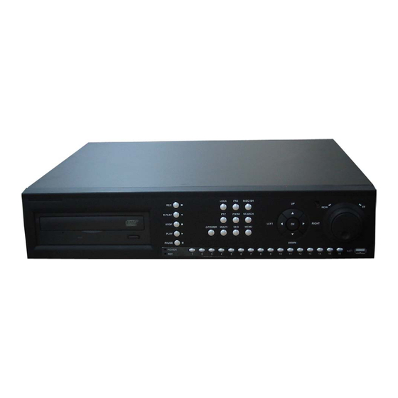
1.4 Name, function & connections 1.4.1 Front view LOCK SEARCH ZOOM MISC/SH R.PLAY STOP LEFT RIGHT MULTI MENU PLAY PAUSE DOWN POWER 10/0 < 16ch DVR > LOCK SEARCH ZOOM MISC/SH R.PLAY STOP LEFT RIGHT MULTI MENU PLAY PAUSE DOWN POWER <... - Page 16 Description: 1. CD-RW/DVD-RW Easy backup by CD-RW/DVD-RW is available. The cover of CD-RW/DVD-RW shows an excellent design. 2. Playback RECORD: Press once to begin recording all active channels. Press again to end recording. R-PLAY: Reverse Playback. Press to begin reverse playback. Under PTZ control menu, used to decrease the speed of Pan, Tilt, Zoom, Focus.
- Page 17 - SH: Press button while using the Shuttle to hold the speed. SEARCH : Press once to open the menu to search for recorded files. PTZ: Pan/Tilt/Zoom. Press once to access the Pan/Tilt/Zoom/Focus control mode. Press again to exit. MENU: Press button to access Main Menu. Press again to return. MULTI (16ch DVR) : Selection button for Screen Division for Live Viewing mode - Live mode: Selection of Screen Division for Live Viewing mode (4, 8, 9, 16 screen divisions)
- Page 18 If you double click “SEQ” , it views 4 screen divisions. This button also can be used for all motions area release purpose on motion detection set up menu. 5. Numeric button - Live Viewing mode button 16ch DVR : 1, 2, 3, 4, 5, 6, 7, 8, 9, 0(10), 11, 12, 13, 14, 15, 16 - Channel selection for Live Viewing and Playback mode, Password inputting, - Channel selection by pushing the button 1, 2, 3, …, 15, 16 8ch DVR : 1, 2, 3, 4, 5, 6, 7, 8,...
-
Page 19: Rear Panel View
1.4.2 Rear panel view < 16ch DVR > < 8ch DVR > < 4ch DVR > 4 & 8 & 16 Channel DVR Operation manual Revision 1.0... - Page 20 Description: VIDEO IN IN : CAMERA INPUT terminal. This is for CVBS signal input. OUT : LOOP OUT terminal. This is for other DVR connection or other device’s input channel. 2. VIDEO OUT VIDEO : VIDEO OUT terminal. CVBS signal is exported. SPOT : SPOT VIDEO OUT TERMINAL.
- Page 21 VGA : Standard Video Out signal is exported. (DSUB-15 male Connector), 10. AUDIO IN/OUT IN : Audio line input terminal OUT : Audio line output terminal. 11. EXTENSION PORT In addition to standard 4 Audio inputs, extra audio input terminals are provided for 8CHand 16CH DVRs.
-
Page 22: Remote Controller Function
1.4.3 Remote controller function ① POWER : button for power on/off. (DVR should be standby or on working status) ② RECORD : button for forced recording (If it’s pressed again, recording stops) ③ INFO BUTTON GROUP : button group for HDD, NET, LOG, INFO. If each button is pressed, the relative information shows and press Menu button for exit ④... - Page 23 Status Up/down Right/left Menu Selection, sub menu Menu move Sub Menu Selection Move Menu Adjust value Channel Play Low speed and playback speed Coverting ⑦ DVR : Reserved. ⑧ MENU : Button for menu. Various sub menu can be selected - To exit, press again the button ⑨...
-
Page 24: Installation
1.5 INSTALLATION 1.5.1 Installation and connection LOCK SEARCH R.PLAY ZOOM MISC/SH STOP LEFT RIGHT MULTI MENU PLAY PAUSE DOW N POWER 10/0 LOCK SEARCH R.PLAY ZOOM MISC/SH STOP LEFT RIGHT MULTI MENU PLAY PAUSE DOW N POWER 10/0 LOCK SEARCH R.PLAY ZOOM MISC/SH... -
Page 25: Camera
1.5.1.1 Camera UDR-416 : It supports 16channel’s Video Input. Upper side is Video Input terminal and lower side is Loop Out terminal. UDR-408 : It supports 8channel Video Input. Upper side is Video Input terminal and lower side is Loop out terminal. UDR-404 : It supports input. -
Page 26: Audio
1.5.1.3 Audio 4 channel Audio Input of RCA standard terminal is basic. 8 & 16channel Audio input is an option and it supports through separate “EXTENSION PORT”. 1.5.1.4 RS-232 Using RS-232 protocol, connects to serial port of PC to control DVR system or to set up system more easily , connecting with PC, which is installed Quick Installer. -
Page 27: Aux/Alarm/Sensor
1.5.1.6 AUX/ALARM/SENSOR 1.5.1.6.1 AUX1~4 It provided total 4 AUX Out Port and it is able to select proper function of the each port in the menu, as user need. It is able to connect with external devices(DVR, Controller), using provided DSUB-25. 1.5.1.6.2 Alarm Out (NO, COM, NC) When alarm is occurred, it provides dry contact output in relay, while alarm is working. -
Page 28: Basic Operation Procedures
Basic operation procedures Power On/Off 2.1.1 Power ON Using either the keypad or the remote control, press the “POWER” button. (Note: In case of power outage or rare instance of system failure, the DVR will reboot automatically) The Power LED light will turn from red to green when it has turned on properly. In a standby mode, the LED is red. -
Page 29: Recording Types
2.5.1 Recording types Enter in Recording setup of menu. For resolution, select either 720*480, 720*240, 360*240 (NTSC) or 720*576, 720*288, 360*288 (PAL). Audio channel is synchronized with the selected video signal. Select Video input quality (Normal/ Enhance/ Fine/ Super fine), Frame rate (120 fps (NTSC) / 100 fps (PAL)), and recording mode. -
Page 30: Backup
Event Search When you press Search, select Event Search from three options listed. Select Date and Time and Channel and you can find recording file list. Please click” OK” button to playback. Backup The DVR has various types of backup methods: 2.8.1 DVD-RW After inserting CD-ROM into CD-RW Drive, push Menu button &... -
Page 31: Uniplayer
Upgrade the S/W(Kernel, Ramdisk) of DVR Install the RAMS program as referred to in section 4.2 of Operation Manual. Execute RAMS program and register selected DVR’s IP address & Port number from the DVR list by clicking following button After selecting the target DVR, enter “admin” for ID and “111111” for default password. This will enable you to access the DVR. -
Page 32: Main Menu Screen
3 Main Menu screen Figure. 3-1 Main Setup screen Camera Setup menu Figure. 3-2 Camera setup screen 3.1.1 Channel A user can select targeted camera. After setting this, live viewing picture will be changed to selected channel automatically. 4 & 8 & 16 Channel DVR Operation manual Revision 1.0... -
Page 33: Camera Name
3.1.2 Camera Name Figure. 3-3 Camera name edit screen User can edit camera name indicated button part of each channel. as explained paragraph 3.1.1. According to above picture 3-3, after keyboard type’s window which is enterable or editable as displayed, user can set channel name with entering new letters and it is available 12 letters at maximum. -
Page 34: Camera Hide
PLAY(▶) Input Space R.PLAY(◀) Input back space MENU Move to “OK” Button Meaning of Key 3.1.3 Camera hide User can make the live screen appear or not by channel with this function. If user sets up “ON” in this function, the live screen of the selected channel does not appear. In case of recording, the recording continues, although screen does not appear. -
Page 35: Ptz Setup
Figure. 3-5 Confirmation box on Picture Setting Default 3.1.5 PTZ setup Figure. 3-6 PTZ setup screen It sets PTZ protocol of targeted channel in the Camera Setup. (Please refer to paragraph 3.1.1 for channel selection) 3.1.5.1 Model No Select the PTZ model or choose “NONE”. 3.1.5.2 PTZ ID Set the PTZ ID: 0 ~ 255... -
Page 36: Reverse Control
The PTZ ID must match the ID number that has been set by the PTZ Controller. Please verify the ID on the Controller first before setting the PTZ ID. 3.1.5.3 Reverse Control Without any further changing of cable connection, user can control PTZ controller by changing reverse direction of PTZ. -
Page 37: Spot
Figure. 3-7 Additional PTZ Menu - Go to Preset : To move the Pan/Tilt drive to the position preset in Set Preset mode. Preset numbers are selected by Left/Right buttons and the Pan/Tilt drive moves to the preset position after pressing OK button. - Set Preset : To preset the position of the Pan/Tilt drive. -
Page 38: Loop Through Setup
3.1.8 Loop Through Setup Set up Loop Through function. Set up is available with 75 or high each channel. Record Setup menu Figure. 3-8 Record setup screen 3.2.1 Resolution Resolution for NTSC is “360 x 240”, “720 x 240”, “720 x 480”. PAL is “360 x 288”, “720 x 288”, “720 x 576”... -
Page 39: Frame Rate
3.2.5 Frame rate User select channel’s recording frame rate and none (no recording), 1, 2, 3, 4, 5, 6, 7, 8, 9, 10, 15, 20, 30(25) fps will be available. The total for all the cannels is max 120 fps(100fps). But, with 720 x 240 (NTSC), 720x288 (PAL) resolution, user should not set to exceed 60(NTSC), 50(PAL) frame per second with accumulated total channel recording. -
Page 40: Record Schedule Setup
3.2.7 Record Schedule Setup Figure. 3-9 Recording schedule setting screen User can select to set recording schedule targeted date, time based week & 24Hours. Move the cursor to the desired position of time by pressing up/down key and set the recording mode at the desired position of time by pressing the OK button with referring to the Help Message per Record Mode on the right position. -
Page 41: Event Setup Menu
Event Setup Menu Figure. 3-10 Event Setup screen 3.3.1 Motion Detection Setting Figure. 3-11 Motion Detecting Setup screen Sets up the motion detecting area and sensitivity. 3.3.1.1 Channel Sets up the motion detecting area and sensitivity for each channel. 4 & 8 & 16 Channel DVR Operation manual Revision 1.0... -
Page 42: Sensitivity
3.3.1.2 Sensitivity Sets up the motion detecting sensitivity. The lower the sensitivity gets the closer to the left the red bar gets. 3.3.1.3 Detection Zone Figure. 3-12 Motion Detecting Area Setup screen Selects the motion detecting area. The sky blue square implies the current cursor and the yellow square implies the area that was already selected as the motion detecting area. -
Page 43: Sensor Setting
3.3.2 Sensor Setting Figure. 3-13 Sensor Setting screen 3.3.2.1 Sensor Type N.O.: Normal Open. Operation mode for the installed sensor’s contact point is usually open in normal condition and changed from open to close at sensor’s detect event. N.C.: Normal Close. Operation mode for the installed sensor’s contact point is usually close in normal condition and changed from close to open at sensor’s detect event. -
Page 44: Alarm Input/ Output
3.3.3 Alarm input/ Output Figure. 3-14 Alarm Output Setting 3.3.3.1 Sensor Configure the alarm out on/off activated by the sensor. 3.3.3.2 Motion Configure the alarm out on/off triggered by the motion detection. 3.3.3.3 Relay Time Configure the alarm duration time. It can be set up from 0 second to 60 seconds in the unit of 5 seconds. -
Page 45: E-Mail Setting
Figure. 3-15 E-Mail Address setting 3.3.6 E-Mail Setting Figure. 3-16 E-Mail Setting 3.3.6.1 Send (Period) Configure the e-mail transmitting cycle. It does not transmit when it is set to NO. The setting time can be set up at the units of within 2 minutes after event, 30minutes, 1, 2, 5, 12, 24 hours. -
Page 46: Smtp Server Ip Address
3.3.6.3 SMTP Server IP address If you click ftp address , key board shaped will turn on the screen. Put the suitable server address (ref.3.6.4.6(STATIC)& 3.6.6.4(PPPoE)) If you want Domain name instead of IP address under PPPoE, STATIC , a suitable DNS server address should be at the network setting menu. -
Page 47: Playback Setup
Playback Setup Figure. 3-18 Playback setup screen 3.4.1 Channel Designate the channel to be viewed when the “PLAY” button is pressed. 3.4.2 Starting Point This starting point configures the starting position when the “PLAY” button is pressed. FIRST: This can search for and replay the oldest recorded images from the selected channel. -
Page 48: Display Setup
Display Setup Figure. 3-19 Display setup screen Determine whether to have the following be shown on the monitor: Camera name, Time/Date, HDD status, Borders. Select either ON/OFF for each item. 3.5.1 ALPHA BLENDING OSD MENU Transparency decision. When it goes to right part, it is not transparent. 3.5.2 VGA Setting Providing suitable VGA port which is suitable to user’s P.C 4 &... -
Page 49: Network Setup Menu
Network Setup Menu Figure. 3-20 Network Setup screen 3.6.1 DDNS setting Set up DDNS (Dynamic Domain Name System) server address & port number. Users can set up two DDNS server address and port, for the faster setting jog shuttle can be used, too. -
Page 50: Remote Connection Login Password
update its IP address to the DDNS server. Therefore DDNS Link on NETWORK SETUP menu should be on. (When IP router is connected from static IP, it is no necessary to setup DDNS link on) By indicating the address of a DDNS Server, the DVR will update its IP address and its MAC address periodically. -
Page 51: Network Type
Figure. 3-22 Remote Connection Login Password screen 3.6.3 Network Type Choose one type from the following: STATIC, DHCP, & PPPoE. Static mode uses fixed assigned IP address in the network. DHCP (Dynamic Host Configuration Protocol) receives an IP address from the DHCP Server, and it may change according to the lease period. -
Page 52: Ddns Link On/Off
3.6.3.2 DDNS Link On/off You can decide if you want to use Dynamic DNS or not under static network type with on/off button. 3.6.3.3 Port Configure the Port number to be used to connect to the DVR system using RAMS (Remote Access &... -
Page 53: Pppoe
3.6.5 PPPoE Figure. 3-25 PPPoE setting 3.6.5.1 Port Please refer to the port setting in paragraph 3.6.4.2 3.6.5.2 Type in your user ID for the ADSL account (PPPoE). The password can contain maximum of 31 characters. Figure. 3-26 ID input screen 3.6.5.3 Password Type in your user Password for the ADSL account (PPPoE),... -
Page 54: Dns Ip
Figure. 3-27 Password input screen 3.6.5.4 DNS IP Setting DNS address of DVR currently used. You can use jog shuttle or number button at front panel. 3.6.6 Changing the Network configuration If users want to change network type of DVR, users must reboot the system. User can restart the new network mode setting after entering “YES”... -
Page 55: System Setup Screen
System Setup screen Figure. 3-29 System Setup screen 3.7.1 DVR Name Type in the name of the DVR you wish to assign. The name can contain maximum of 12 digits. Figure. 3-30 DVR name screen Name the DVR : type in the DVR name. Up to 12Ccharacters. 4 &... -
Page 56: System Password
Click “OK” when finished. 3.7.2 System Password Figure. 3-31 System password set up Set up part for system password, related function and application. This is a part of installation, actual system password, related function and password application. 3.7.2.1 Password Setting To change system password: First, type-in the current password, confirm. -
Page 57: Password Apply
Figure. 3-32 Password input screen 3.7.2.2 Password Apply Determine whether the system password has to be applied to power On/Off. The applicable features are recording close, enter menu, system off. Users can set up password ON/OFF for each feature. Setting to On, when each feature starts, users have to confirm password for each step. Setting to Off, users can use any confirmation of password. -
Page 58: Set Up Time / Date
Figure. 3-33 Set up Time/Date 3.7.3.1 Set up Time / Date Set up date and time on the system 3.7.3.2 Time / Date Format Set up format for date and time. There are two types of time: 24hr circle/ 12hr circle. Date format can be set up as the following: YYYY/MM/DD, MM/DD/YYYY, DD/MM/YYYY. -
Page 59: Buzzer
3.7.3.3.2 End date (m/d) Set up end date in Day Light Saving Time mode. 3.7.3.3.3 Apply Hour Configure Day Light Saving Time. 3.7.4 Buzzer Users can turn the buzzer ON/OFF depending on the situations. Usable situation is Sensor, Motion, & Video Loss. When users activate the buzzer, buzzer will make a sound when there any event occurs. -
Page 60: The Number Of Hdd
Figure. 3-35 HDD Setup image 3.7.6.1 The number of HDD Show the HDD quantity that is built –in. 3.7.6.2 Write Mode Set up writing type in recording. Types are ‘Once’ and ’Overwrite’. If set up by ‘Once’, HDD can record until the Full state. If set by ‘Overwrite’, HDD will record continuously by start overwrite oldest data. -
Page 61: Aux Port
3.7.6.4.2 Format This is function for internal HDD formatting and you must reboot the system after this instruction. Confirmation box on format will appear after entering format key. User can format and erase all information of HDD, after entering “YES” key button. Figure. -
Page 62: Function
3.7.7.2 Function The following list contains a brief description of each function. 3.7.7.2.1 Direction : IN UNUSED: Do not use the AUX port. ALARM RESET IN: Pause alarm or buzzer when event occurred RECORD START IN: Record is on while external signal comes in. RECORD ON/OFF: Recording start/stop during user push the button &... -
Page 63: Software Upgrade
3.7.9 Software Upgrade Users can upgrade the software of Ramdisk and Kernel using the USB flash drive (thumb drive) by the following steps. - Get the latest version of software (Ramdisk/Kernel) from distributor - Copy the downloaded files from the PC to the USB memory. - Connect the USB memory to the USB port. -
Page 64: Backup Device
Figure. 3-41 Backup screen 3.8.1 Backup Device Set up the device for backup. USB / CD-RW are available 3.8.2 Start Time Input the start of backup date and time. 3.8.3 End Time Input the end of backup date and time. 3.8.4 Channel Choose the channel to backup. -
Page 65: System Log
System Log It is for displaying major system events. The items that manage by Log are Video Loss, Power On, Power Off, Menu entry, HDD Full, failure of E-mail transmission Figure. 3-42 System Log 3.10 System Information Figure. 3-43 System Information 3.10.1 Video type It shows that present Video type of System is NTSC or PAL. -
Page 66: H/W Version
3.10.2 H/W version It shows the H/W Version of system. 3.10.3 S/W version It shows the S/W Version of system. 3.10.4 KERNEL version It shows the S/W Version of KERNEL. 3.10.5 Mac Address It shows Mac Address of system. 3.10.6 Audio Shows audio part availability. -
Page 67: Search By Calendar
3.11.1 Search by Calendar Figure. 3-45 Search by Calendar 3.11.1.1 Calendar View When you click specific date, it will be showing recorded data as drawing. 3.11.1.2 Drawing Color Figure. 3-46 Calendar Search Screen Red : Enforced Recording Green: Motion Event Recording Purple: Sensor Event Recording White : No Recording 4 &... -
Page 68: Hour( Time)
3.11.1.3 Hour( Time) It is composed of 24hours. Recording status can be distinguished by color. Even though Your recording mode is Motion plus Sensor mode, but if motion recording is bigger than Sensor, then the color will be green. 3.11.1.4 Display by minutes If there are some recording on a specific time and channel, it shows suitable color on a specific minute time zone. -
Page 69: Still Image Search
3.11.3.1 Still Image Search 3-53 Still Image search Screen 3.11.3.2 Still Image USB back up Click the specific file and push “PLAY” button, still image will be copied. 3.11.3.3 Converting Still image file into JPG format. - Execute simpleplay_m4.exe.file - Open the file to change into jpg - Click the second disc button of Toolbar menu #2 and save it as jpg or bmp type. -
Page 70: Screen Of Played Back
3.12.1.2 Screen of played back. Figure. 3-54 Screen of playback 3.12.1.3 Control during playback 3.12.1.3.1 Stop of Play back If user needs to stop playback, user should press button “STOP” in the remote controller of in the system, and play back stops and live screen is coming back. In case of calendar search, “SEARCH “... -
Page 71: Playback Of Still Image
In order to change direction from Forward to Backward, user press the button “REVERSE PLAY” and backward playback starts with normal speed. On the contrary, to change direction from Backward to Forward, user press the button “PLAY” and Forward playback starts with normal speed. -
Page 72: Control During Still Image Play Back
3.12.2.3 Control during Still Image Play back 3.12.2.3.1 Stop of play back To stop the playing back, User press button “STOP” or “ SEARCH”. Playback stops and screen of search list appears. 3.12.2.3.2 Next screen Press Button “RIGHT” and next screen is played back. 3.12.2.3.3 Previous screen Press Button “LEFT”... -
Page 73: Osd
Figure. 3-50 Network Information 3.13.2 OSD Turns on/off the OSD (On Screen Display). It substitutes the OSD button on the remote control. 3.13.3 Audio Mute Turns on/off the audio. It substitutes button on the remote control. 3.13.4 HDD Displays the HDD information. It substitutes the HDD button on the remote control. 3.13.5 LOG Display the System Log. -
Page 74: Client Program
Client program Overview of DVR RAMS_M4 (Remote Access & Monitoring System MPEG4) is used to remotely access, monitor, and operate the DVR for real-time live viewing, playback, backup, on-the-fly recording, and control over the LAN/WAN. UniPlayer_M4 is a viewer with functions for recording, capturing, & backing up files. QuickInstaller_M4 is a setup configuration template for quick &... -
Page 75: Rams_M4 (Remote Access & Monitoring System Real-Time)
RAMS_M4 (Remote Access & Monitoring System Real-Time) 4.3.1 Screen and button ① Screen capture button, Video record button ② Screen display ③ Channel display button, Sound control button ④ If logo is clicked, program version window appears. ⑤ Time indicator ⑥... -
Page 76: Connecting To Dvr
⑫ Minimizing button ⑬ Close program 4.3.2 Connecting to DVR Click icon to open the DVR list. ① This box allows the user to select the IP address assigned to the selected unit. This is required for making a network connection. ②... -
Page 77: Uniplayer_M4 Link
4.3.3 UniPlayer_M4 link If you click this button on main menu, UniPlayer_M4 program will be executed. Regarding the UniPlayer_M4 program, please refer to the article 4.3 4.3.4 Full-screen display If you click button on the main menu, you can see full screen pictures. If users press the key of ESC, you will return to the selected screen. -
Page 78: Program Setup
4.3.5 Program setup If users click this button in the main window, window of program setup appears. ① Capture a still image and select a folder where the image is recorded ② Select the image of water mark to be input in the still image ③... - Page 79 => DVR (live viewing) => DVR (Recording mode) 4 & 8 & 16 Channel DVR Operation manual Revision 1.0...
-
Page 80: Dvr Playback Search
4.3.7 DVR playback search This button is used for playback search, playback, and backup functions for DVR and after logging in by admin. < Recorded data by search function > 4 & 8 & 16 Channel DVR Operation manual Revision 1.0... - Page 81 < Tips for DVR backup search > 4 & 8 & 16 Channel DVR Operation manual Revision 1.0...
- Page 82 < Searched screen, when pushed backup button > 4 & 8 & 16 Channel DVR Operation manual Revision 1.0...
-
Page 83: Dvr Playback
4.3.8 DVR playback It shows recorded data by date and time on the time table. It starts playback, upon press the Play button, after selecting of date and time in order. To recall the current calendar data from DVR, press the Reload button. To close the screen, press the Close button. - Page 84 ① This is to be converted into Playback from current status. ② Those buttons are for converse-playback, playback, temporary stop, stop, backward one screen, forward one screen, Slow, Fast ③ This is to view of whole screen. Above picture on the screen is whole screen. ④...
-
Page 85: Dvr Backup
Play stored files quickly. User can control by clicking this button 4.3.9 DVR backup It shows recorded data in the calendar and time table. It is able to select stating time and closing time of backup by mouse. It is available to select backup mode by Full Frame or Skip Frame. It may be taken longer time to backup by Full Frame, as it backup all of recorded data. - Page 86 Below screen shows the indication by recording status.. After selecting a file at DVR backup list, user can start to backup with pushing start button The destination of backup files is below of backup folder located in directory of program installed.
-
Page 87: Dvr Setting
< This screen shows backup status of recorded CH2, CH4 and CH6’s data > 4.3.10 DVR Setting This button is for linking into quick installation program, which is used to manage setting parameter of DVR easily. It can be activated after logging in by admin. The setting parameter of DVR are displayed. -
Page 88: Watermark Insertion
① Watermark insert : Select check box to insert watermark to still image. ② Fixed file name : It is stored still image, which was fixed by program. ③ Select file name : It stores still image with preferable name in preferable folder. ④... -
Page 89: Pan/Tilt, Zoom/Focus
① Select the channel, you desire to record. ② Continuous recording : It keeps recording, until user make the recording stop. ③ Recording duration time : It keeps recording, while it is set up. User is able to make the recording stop manually. -
Page 90: Hdd Information
4.3.16 HDD Information The orange color part of above box means used Hard Disk and the rest of white color means remaining unused part of the HDD. If you click the white color part, then the window of HDD information pops up. You can select HDD there, which you want to check and it shows rest capacity of the HDD at KByte. -
Page 91: S/W Upgrade Of Dvr
4.3.18 S/W upgrade of DVR S/W upgrade window is activated on pushing S/W upgrade button in the program version check screen Select file type, which you would upgrade. And input DVR address, port, model and password in order, which you would upgrade. After that, update would start, when you press Update Start button. -
Page 92: Program Minimizing
4.3.19 Program minimizing Rams_M4 program is minimized 4.3.20 Close program Closed Rams_M4 program UniPlayer_RT 4.4.1 Screen and button ① Button per channel (Capture, Print) ② Playback picture ③ Indicator for playback progress rate ④ Reverse playback, playback, still, pause, reverse phase, forward phase, slow, fast ⑤... -
Page 93: Directory Search
⑧ Search list ⑨ File path is displayed if selected at search list ⑩ Button for playback of UMV file directly, after file opening. ⑪ Button for searching of still image ⑫ Button for searching of stored file in the PC in type of calendar. ⑬... -
Page 94: Search Of Still Image
4.4.3 Search of still image It is able to search by the folder of still image, stored date, DVR name, channel and keyword information. If you do not select any of searching condition, then it shows all of the files, which is stored in the still image folder. -
Page 95: Calendar Search
<Searched screen by channel 4 > 4.4.4 Calendar search It shows recorded data or backup data in type of calendar. 4 & 8 & 16 Channel DVR Operation manual Revision 1.0... - Page 96 4 & 8 & 16 Channel DVR Operation manual Revision 1.0...
-
Page 97: Still Image Capture
< Playback screen of real-time image, after search > 4.4.5 Still Image Capture Save replaying images into still image by capture. Besides users can capture image by push capture button for each channel or push capture button at the foot of a screen. Still image will be saved in a path of which is established in RAMS_M4’s setup section screen ①... -
Page 98: Input Water Mark
③ Select file name : User is able to store the still image with desired name in the desired folder. ④ Keyword insert : To do easy search in Uni playerRT, it is able to insert keyword. Close : To close still image. ⑤... -
Page 99: Water Mark Drawing
4.4.9 Water mark drawing When still image is display, if push this button watermark will be drawn. If you find other color except black, white, blue color, image file must get damaged. Push this button one more time, reverts to original image state. =>... -
Page 100: Panorama
Watermark viewing screen. If you find other color except black, white, blue color, image file must get damaged. 4.4.10 Panorama You can see the panorama screen when you push this button while file playing. (Button will change into like this button. . - Page 101 < Screen in panorama mode. > < Image when click one screen in panorama mode.> 4 & 8 & 16 Channel DVR Operation manual Revision 1.0...
-
Page 102: Check The Program Version
4.4.11 Check the program version. Click right part of logo to confirm version. 4.4.12 Program minimizing UniPlayer_RT program is minimized 4.4.13 Close Program Close UniPlayer_RT program Quick Installer 4.5.1 Select model Clicks to select DVR model name and video type in order to set system parameters. 4 &... -
Page 103: System Parameter Setting
4.5.2 System parameter setting * Right parts on System parameter setting window is same form as Main menu used in DVR system. Users can change DVR system parameter by entering each menu. * Main menu description * File ->Open: Read to display saved parameter values from DVR system. 1. - Page 104 After Setting system parameters Derive system parameters from DVR => Network mode as communication media Enter assigned network access password for Admin. After authenticated, users can communication between DVR using network. =>Serial mode as communication media Enter assigned network access password for Admin. After authenticated, users can communication between DVR using serial port.
-
Page 105: Connection By Internet Explorer
Connection by Internet Explorer 4.6.1 Security setup In “Internet Option” Menu, Choose “Trusted sites” then click “Sites…” button, Your DVR address 4 & 8 & 16 Channel DVR Operation manual Revision 1.0... -
Page 106: Download Activex Control
Add your DVR Address.(it possible “IP” or “MAC”). 4.6.2 Download ActiveX control In order to download ActiveX control, press “confirmation” button, when the message Appears, and download in the PC. (If “cancel” button is clicked, program may not be worked) 4.6.3 Connection with DVR Fill the address of DVR Mac address or IP up in the address window of Internet Explorer. -
Page 107: Connected Screen
4.6.5 Connected screen 1. In the lower part of screen, there are buttons button to select the screen division & button to search the moving picture.. 2. In the right part of screen, there is a button to control PTZ. PTZ control is available when one screen is selected, In order to select one screen, double click the required channel. -
Page 108: Search
4.6.6 Search Same function as search of DVR playback search Please refer to the article 4.3.7 4 & 8 & 16 Channel DVR Operation manual Revision 1.0... -
Page 109: Playback
4.6.7 Playback This is the screen when it playback.. Playback control button in the right parts has same function as DVR playback in RAMS_M4. Please refer to the article 4.3.8 (DVR manual) 4 & 8 & 16 Channel DVR Operation manual Revision 1.0... -
Page 110: Appendix
5 Appendix How to install HDD( Hard disk) 5.1.1 How to install HDD It is available to install maximum 2pcs SATA Interface’s HDD. CAUTION RISK OF ELECTRIC SHOCK DO NOT OPEN Bolt the ”A” part out, using driver. 4 & 8 & 16 Channel DVR Operation manual Revision 1.0... - Page 111 TOP COVER is able to apart from BOTTOM CASE. It is assembled bracket for HDD inside of DVR. Bolt the ‘B’ part out. (Seperate of BRACKET ) 4 & 8 & 16 Channel DVR Operation manual Revision 1.0...
- Page 112 Assemble HDD, referring to above picture. Upper side picture for assembling of 1 piece HDD and lower side picture for assembling of 2pcs HDD. Recommended bolt type is M3.5 x 5L for assembling of HDD. (It is packed with HDD, when you purchase it) 4 &...
- Page 113 When you finished to assemble HDD and BRACKET, install assembled HDD set in DVR. You can refer to above picture for HDD installation. Be careful the connector direction of HDD. When you install HDD in a set, be careful to be not hold the FRONT CABLE between HDD set and DVR.
-
Page 114: Terminal Information
Terminal Information 5.2.1 DSUB-9P (RS-232) Name Description Receive Data Transmit Data Signal Ground 4 & 8 & 16 Channel DVR Operation manual Revision 1.0... -
Page 115: Dsub-25P ( Aux / Alarm / Sensor)
5.2.2 DSUB-25P ( AUX / ALARM / SENSOR) NAME DESCRIPTION NAME DESCRIPTION AUX0 SENSOR INPUT 6 User AUX1 Programmable SENSOR INPUT 7 Auxiliary AUX2 SENSOR INPUT 8 Output Port AUX3 SENSOR INPUT 9 Sensor POWER OUT SENSOR INPUT 10 Input Port RELAY_NO SENSOR INPUT 11 Relay... -
Page 116: Factory Default Value
Factory Default Value 5.3.1 Main Menu Menu Default Remark Main Sub menu1 Sub menu 2 Sub menu3 menu Camera Channel Channel number CH 1~CH 16 setting Camera name CH 01~CH 16 Hide screen Screen adjustment Contrast 9 Level Max. 16 Levels Bright 9 Level Color... - Page 117 Recording speed (FPS) NONE, 1, 2, 3, 4, 5, 6, 8, 10, 15, 30 Recording condition MANUAL MANUAL, CONTINOUSE, MOTION, MOTION+SENSOR CONT+EVENT CONT+EVENT Screen quality SUPER FINE Recording speed (FPS) 30 FPS Event Motion detection Channel CH 1 CH 1 ~ CH 16 setting setting Sensitivity...
- Page 118 setting Playback starting 5 MIN AGO FISRT, time 5 MIN AGO, 30 MIN AGO, 1 HOUR AGO, 6 HOUR AGO, 12 HOUR AGO 24 HOUR AGO, Screen Camera name indication Date / Time setting HDD usage status Outline VGA setting 640x480 640x480, 800x600,...
- Page 119 Standard time zone Time GMT, America/Anchorage, America/Chicago, America/Dawson, America/Denver, America/Los_Angles, America/Mexico_City America/New_York, America/Sao_Paulo, America/Toronto, America/Winnipeg, Asia/Dubai, Asia/Istanbul, Asia/Seoul,, Asia/Tehran, Asia/Tokyo, Australia/Darwin, Australia/Perth, Australia/Sydney, Europe/Amsterdam, Europe/Athens, Europe/Berlin, Europe/Brussles, Europe/Copenhagen, Europe/Dublin, Europe/Helsinki, Europe/London, Europe/Madrid, Europe/Moscow, Europe/Oslo, Europe/Paris, Europe/Prague, Europe/Stockholm, Europe/Tallinn, Europe/Vienna, Europe/Warsaw, Europe/Zurich, Pacific/Auckland, Pacific/Chatham...
- Page 120 Delete by force [ some 1~100, OFF days ago] HDD 1 Usage capacity Used Cap. / Total Cap. Format HDD 2 Usage capacity Used Cap. / Total Cap. Format Aux port setting Working HIGH / LOW HIGH Function UNUSED UNUSED, ERROR OUT, DISK...
-
Page 121: Search Menu
5.3.2 Search Menu Menu Default Value Ref. Main Sub menu1 Sub menu2 Menu menu3 Calendar Search CURRENT SYSTEM DATE DATE : One day before START TIME Time : Current system time Date : Current System date Event Search Search END TIME Time : Current system time CHANNEL Still... -
Page 122: Protocol
Protocol 5.4.1 Code table Protocol Description Remarks kmute Audio Mute krec Record khdd HDD Information knet Network user information klog Log Display kinfo System Information knum1 Number 1 knum2 Number 2 knum3 Number 3 knum4 Number 4 knum5 Number 5 knum6 Number 6 knum7... -
Page 123: Usage
Shuttle left 1Step Shuttle left 2Step Shuttle left 3Step Shuttle left 4Step Shuttle left 5Step Shuttle left 6Step Shuttle left 7Step kjleft Jog left kjright Jog right kpower Power 5.4.2 Usage - System protocol to control DVR from remote client software installed in PC or remote controller. - It maps button function of remote controller with front key in the front panel of DVR. -
Page 124: Recording Mode, Quality, Fps, Hdd Time Table
Recording mode, Quality, FPS, HDD time table Recording time by HDD capacity(hours), for 1 channel Frame Resolution Quality System Rate 300GB 500GB 30 FPS 425.52 709.19 1418.39 15 FPS 703.19 1171.99 2343.97 Super 10 FPS 968.51 1614.18 3228.36 Fine 5 FPS 1744.38 2907.31 5814.61... - Page 125 1 FPS 8095.73 134952.88 26985.75 30 FPS 577.21 962.02 1924.03 15 FPS 931.37 1552.28 3104.56 10 FPS 1247.96 2079.93 4159.86 Enhanced 5 FPS 2177.47 3629.12 7258.24 1 FPS 10524.44 17540.74 35081.48 30 FPS 489.37 1148.96 2297.91 15 FPS 1115.67 1859.44 3718.88 10 FPS 1475.39...
- Page 126 Recording time by HDD capacity(hours), for 1 channel Frame Resolution Quality System Rate 300GB 500GB 25 FPS 441.59 735.98 1471.95 20 FPS 513.39 855.65 1711.29 Super 9 FPS 1025.11 1708.51 3417.03 Fine 5 FPS 1602.71 2671.18 5342.36 1 FPS 7700.81 12834.69 25669.38 25 FPS...
- Page 127 20 FPS 704.76 1174.60 2349.21 9 FPS 1288.71 2147.85 4295.69 5 FPS 1985.74 3309.57 6619.15 1 FPS 9020.95 15034.92 30069.84 25 FPS 709.51 1182.52 2365.04 20 FPS 837.49 1395.81 2791.63 9 FPS 1503.49 2505.82 5011.64 Normal 5 FPS 2304.62 3841.04 7682.08 1 FPS 10184.95...
Need help?
Do you have a question about the DVR-404 and is the answer not in the manual?
Questions and answers