
Related Manuals for Asoni CAM633


Summary of Contents for Asoni CAM633
- Page 1 H.264 23X Network Speed Dome CAM633 / CAM633A / CAM633B User’s Manual Date: 7/20/2012 Firmware Version: V1.0.32...
-
Page 2: Table Of Contents
Content Content ............................1 Preface ..........................3 Product Specifications ....................... 3 Product Installation ......................6 A. Part Names ........................6 B. Hardware Installation ...................... 7 Surface Mount onto Ceiling (Without Housing) ..............7 Housing Installation ....................... 8 Cables Connection........................ 9 I/O Connections ........................ - Page 3 Schedule ..........................53 OSD Menu .......................... 55 A. System Info ........................57 B. Display ........................... 58 C. Camera ........................... 59 D. Scan ..........................67 Control ........................... 70 Privacy Mask ......................... 72 Alarm ..........................74 H. Initialize .......................... 74 Network Configuration ..................... 76 A.
-
Page 4: Preface
1. Preface This camera is a network speed dome camera. It builds in web server. User views real-time video via IE browser. It supports H.264, JPEG and MPEG4 (3GPP Only) video compression which provides smooth and high quality video. This camera is equipped with high resolution CCD sensor and powerful 23X zoom lens that can used for wide angle observation and detail viewing to the far-end object as well. - Page 5 Hardware CPU / RAM / ROM ARM 9, 32 bit RISC / 256MB / 16MB Image Sensor 1/4" Sony SuperHAD CCD, 540 TV lines Lens 1/4", 23X Zoom Lens 3.84 ~ 88.4 mm, F1.6 ~ 3.0 Day / Night Auto / Manual, Mechanical IR Cut Filter Illumination Color mode: 0.6 lux Black/White mode: 0.1 lux...
- Page 6 Pan/ Tilt Speed Call preset: 240 /sec Auto scan: Variable speed, up to 120 /sec Manually: Variable speed, up to 240 /sec Preset Point 128 Preset points Patrol Patrol for presets, Group patrol, Pattern patrol, Auto pan Focus/ Iris Auto / Manually Motion Detection Yes, 3 different areas Event Trigger...
-
Page 7: Product Installation
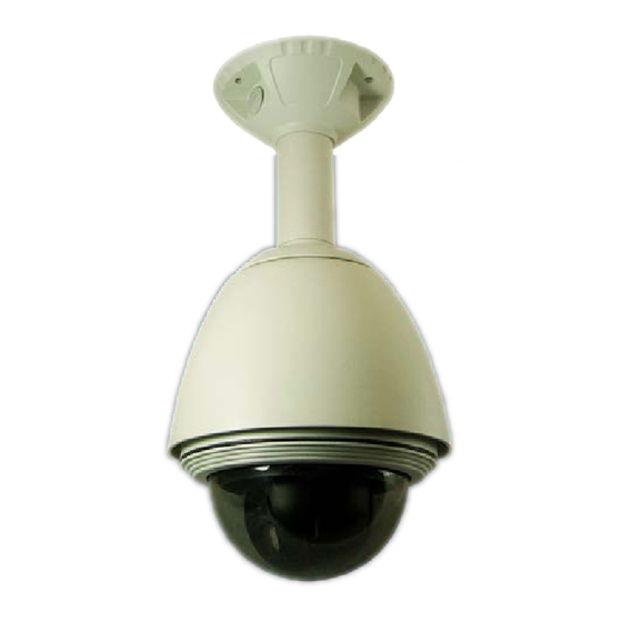
3. Product Installation A. Part Names Power Jack (DC 12V) Digital I/O Analog Video Output (Black) Audio Input (Red) Audio Output Network Connector To connect the included power adapter. Power Jack: Purple: Digital In 1 Digital I/O: Red: Digital In 2... -
Page 8: Hardware Installation
B. Hardware Installation The following items are supplied with the speed dome for the camera mounting. Description Photo Mounting Base To hold the camera on ceiling surface Screws for the build of camera’s holding Screw Pack structure Surface Mount onto Ceiling (Without Housing) 1. -
Page 9: Housing Installation
Housing Installation Power cord of heater Power jack of speed dome and fan (from housing) Power adapter Wall-mount Pendant-mount... -
Page 10: Cables Connection
Cables Connection 1. Connect the cable of Digital I/O, Video output, Audio output and Audio input if you want to use these functionalities. 2. Connect Ethernet cable for network connection. 3. Connect power adapter to turn on the camera. 5. If the camera is PoE model, the power adapter is not necessary. The camera will get the power from the PoE injector or PoE switch. - Page 11 I/O wires – used in application, for e.g., motion detection, event triggering, alarm notifications. It provides the interface to: 2 sets of Digital Input (Digital In + GND) – The digital inputs for connecting devices that can toggle between an open and closed circuit, such as PIRs, door/window contacts, glass break detectors, etc.
- Page 12 Relay Output COM: Common pin. N.O. (Normally Open): Max. 1A / 24VDC or 0.5A / 125VAC.
-
Page 13: Monitor Setting
C. Monitor Setting 1. Right-Click on the desktop. Select “Properties” Change color quality to “Highest (32bit)”. -
Page 14: Ip Assignment
PC must be in the same subnet. For more information about subnets, please consult your network administrator. “Asoni IP Search” is a utility that provides an easier, more efficient way to configure the IP address and network settings of the network camera in Local Network (LAN). - Page 15 2. IP Search searches all the network devices which connect to the intranet and lists on the window. Click [Search] button to search again. 3. From the list, click and select the device with the MAC Address that corresponds to the device that is to be configured.
-
Page 16: Live Video
4. Live Video Start the IE browser, type the IP address of the network camera in the address field: http://<IP of camera> If the “HTTP Port” has been changed from “80”, type the URL as: http://<IP of camera>:<HTTP Port> After link to the camera, it will show a dialogue box. - Page 17 When popup the following dialogue box, click [Yes].
- Page 18 The web page of the device shows as following. If you are using IE 8.0 or above, please click “Compatibility View” icon to make this web page works properly: ⑤ ① ② ③ ⑨ ⑩ ⑥ ⑦ ④ ⑧ Streaming : Select the streaming 1 or 2 from the pull-down list to display.
- Page 19 Online Visitor : Shows how many users connect to this device. OSD Menu : This camera has many functions available to users for setting and adjusting. Most advanced functions are accessible through OSD (On-Screen-Display) Menu. Please refer to OSD Menu chapter for the operation.
- Page 20 Preset Point : This camera supports 128 preset points. Select the preset from pull-down list, move Set / Change Preset camera to the desired position, input a name in Point: “Name” box, and then click button. Preset Point Select the preset from pull-down list and then Go to Preset Point: click [Go], camera will go to the position.
- Page 21 Pattern 1~4: To make camera patrol the selected pattern. Pattern is a function allows you create specific path with individually-defined stops. You can OSD Menu Scan create the pattern in Pattern. Selected Group: To make camera move around all the selected groups.
- Page 22 start position and panning speed first. Start “Auto Pan”: Click button under the pull-down list. Stop “Auto Pan”: Click button under the pull-down list. Function Buttons : Click these buttons will perform the following functions. Full Screen : Click this button or double-click the video, the video will change to full screen mode.
- Page 23 Relay Out (Time Switch) : Click the button to manually turn on the Relay via the built-in Relay Out, after the interval time is passed, the Relay will be Configuration turned off automatically. The interval time can be set up in Event Handling ...
-
Page 24: Configuration
5. Configuration Click [Configuration] button to get into the configuration page. Click [Live View] button to back to the Live-View page. A. System System Information Set up the camera name, select language, and set up the camera time. System Information... - Page 25 Server Information MAC Address: The MAC address of the Ethernet network card in the device. Server Name: You can type a name into this field to identify this device. Show on Status Bar: Determine whether show the server name on the Status Bar. Default Language: Select the default language for the user interface.
- Page 26 Time Setting Date Format: Select the format to display the date. Time Zone: Select the GMT to match your time zone. Enable Daylight Saving: If using “Daylight Saving”, enable this option and select the start and end time. Synchronize with NTP Server: Select this option and type the IP address of a NTP (Network Time Protocol) server, this device will synchronize the time with the NTP server via network.
- Page 27 The date and time remain the same: Keep the current date and time without change. After set up, click [Apply] to save the settings.
-
Page 28: User Management
User Management You can add, remove and manage the users in this page. This device supports 4 user groups: Administrator: The administrator can view, operate and configure all functions and settings of this device. PTZ: The users in PTZ group can view and operate all functions in Live-View page. - Page 29 then click [Add/Set] to save the user. User List This table lists the current users. Edit: To change the username and password, click [Edit] and modify the administrator or user in the pop-up window. Remove: To remove the user, click [Remove].
-
Page 30: System Upgrade
System Upgrade This page allows user to upgrade firmware, restart device and restore the factory default settings. System Upgrade Firmware Upgrade The firmware can be upgraded online. To update the firmware, click [Browse…] to select the new firmware file, and then click [Upgrade] to the procedure. -
Page 31: System Logs
System Logs System Logs System Status Logs Click the [View] button on the right side to list the logs of system status. Motion Trigger Logs Click the [View] button on the right side to list the logs of motion detection. Digital-In Trigger Logs Click the [View] button on the right side to list the logs of digital input detection. -
Page 32: Video/Audio Setting
B. Video/Audio Setting Video Format This device supports H.264/MJPEG and MPEG4 (only for 3GPP streaming) Triple Mode and Triple Streaming, set the video parameters in this page. Video Format... - Page 33 Streaming 1 and 2 Output Setting Basic / Advanced Mode: Select the mode to configure the parameters. Advanced mode provides more detail parameters for setting. Resolution: Select the resolution from the pull-down list. Frame Rate Per Second: The video refreshing rate per second. Select the frame rate from the pull-down list.
- Page 34 Since the bandwidth of 3G is not fast usually, the 3GPP streaming will be set to the following configuration: Resolution – Fixed to 176x144. Frame Rate –Fixed to 5FPS. Video Format – Fixed to MPEG4. Audio Format – Fixed to AMR. 3GPP Path: Assign a name to identify the 3GPP video stream To view the live video with a 3G mobile phone or PDA, open “Streaming Player”...
-
Page 35: Image Setting
Image Setting Image Setting Privacy Mask For the security purpose, there are 3 areas can be setup for privacy masks, the masked areas will not be shown in Live-View and recorded file. To set up or clear the privacy mask, click [Draw/Clear Area] button, and then use mouse to drag the area on the video. -
Page 36: Audio Setting
Audio Setting This device supports 2-way audio. Audio from Device to Local PC For this device to local PC, select [Enable] and then click [Apply] to start this function. If set to [Disable], the [Voice] icon on Live View page is not workable. Audio Setting Audio from Local PC to This Device For local PC to this device, click [Chatting] icon on the Live View page. -
Page 37: Network Setting
C. Network Setting Network Setting Network Setting... - Page 38 IP Assignment DHCP: If this device behinds a router and the router provides DHCP service, using DHCP, this device will get all network parameters from the router automatically. Static: Assign IP address, subnet mask, gateway, and DNS manually. Port Assignment Set the port if necessary.
- Page 39 RTSP Server Setting RTSP Server: The video stream can be direct retrieve via RTSP connection, you can close this function by disable this option. RTSP Port: Set the port for transfer the video and audio. The default is “554”, change the port if you want to use router’s NAT (Network Address Translation) to make this device can be linked from Internet.
- Page 40 keeping the RTSP connection, this device will terminate the RTSP connection. If select “Disable”, this device will always keep the RTSP connection. If the “Time-out” error happens on NVC side, please disable this function. After set up, click [Apply] to save the settings.
-
Page 41: Mail / Ftp / Samba Setting
Mail / FTP / Samba Setting To send out the event video to E-mail, FTP or Samba network storage, please set up the configuration first. Mail / FTP/ Samba... - Page 42 Mail Setting Login Method: This device provides 2 kinds of mail settings. “Anonymous” for the mail server which doesn’t need login with user name and password. “Account” for the mail server which needs login with user name and password. Send Mail Server: The IP address or URL of the send-mail server.
- Page 43 FTP Port: The port of the FTP service. Default is 21. Store Path: The path to save the sent video file. FTP Mode: Select “PORT” or “PASV to fit the FTP server. “PORT” is for sending file to an Active FTP server; “PASV” is for sending file to a Passive FTP server. Auto Create Folder by Date: If select “Yes”, a folder will be created under the “Store Path”...
-
Page 44: Pppoe Setting
PPPoE Setting If this device connects to an ADSL modem directly and want to use PPPoE connection, set the parameters in this page. PPPoE Setting PPPoE Connection Select [Enable] to use PPPoE. Type in user name and password for the ADSL connection. -
Page 45: Ddns Setting
DDNS Setting This device supports DDNS, set the parameters in this page. DDNS Setting DDNS Setting There are several DDNS providers can be selected. Select the provider from the pull-down list, input Hostname, User name, Password and the Schedule Update time, and then click [Apply] to connect to the DDNS provider. - Page 46 Update Failed, check your internet connection: Network connection failed. Update Failed, please check the account information with you provider: input hostname, username or password may be wrong.
-
Page 47: Event Handling
D. Event Handling Event Setting This device supports multiple event settings. Event This device supports 2 kinds of event detections: Motion Detection. Digital Input Detection. - Page 48 Motion Detection This device allows 3 areas for detect motion. When motion detection is triggered, it can send the video or snapshot to specific mail address; transmit the video or snapshot to remote FTP server or Samba network storage; trigger the digital out. Set the Area: To set up or clear the motion area, click [Draw/Clear Area] button on “Set Area”...
- Page 49 FTP: When the motion detection is triggered in this area, send the recorded video or snapshot to the specific FTP site. Save to Samba: When the motion detection is triggered in this area, send the recorded video or snapshot to the Samba network storage. To set the mail account FTP site and Samba network storage, please refer to Configuration ...
- Page 50 Motion! The moving object smaller than the 50% of the The moving object larger than the 50% of the motion motion area, it will not be detected! area, it will be detected, and the motion is triggered! To detect the smaller moving object, use 3 motion areas to replace a large motion area, refer the figure below: Motion! The moving object will be detected when it is in any of...
- Page 51 Snapshot (Single): This option is available when the “Video Format” of streaming 1 is set as “JPEG” in Video Format page. When an event (Motion Detection or Digital Input Detection) is triggered, this device will take a snapshot with JPG format. Pre and Post Record Time Setting Configure the record time for the event recording file.
-
Page 52: I/O Setting
I/O Setting This device provides Digital Input and Digital Output. When the Digital Input is triggered, it can send the video or snapshot to specific mail address; transmit the video or snapshot to remote FTP server or Samba network storage; trigger the digital out. I/O Setting Digital Input Setting Input 1 / 2 Sensor Type:... - Page 53 E-Mail Subject: The subject of the E-mail will be sent. Detection Interval: This option provides two functions. The interval time between multiple detections. For example, if the time set to 10 seconds, when the Digital Input is triggered at time 10H:05M:10S, the next trigger will be accepted after 10H:05M:20S.
-
Page 54: Schedule
Schedule This function provides the schedule for the following: Send Snapshot with the Scheduled Time: automatic send a snapshot to the E-mail address, FTP server or Samba network storage. The interval time can be set. Activate and Stop the Motion Detection with Scheduled Time: if the “Enable Configuration ... - Page 55 light-grey means the time is unselected. Select / Unselect Specific Time: Click the square of the time table to select or unselect the specific time. The square in green means the time is selected; the square in light-grey means the time is unselected. Send Snapshot with Scheduled Time Enable / Disable: To enable or disable the schedule function.
-
Page 56: Osd Menu
6. OSD Menu This camera has many functions available to users for setting and adjusting. Most advanced functions are accessible through OSD (On-Screen-Display) Menu. Open OSD Menu Click button. Move Cursor Click Left / Right or Up / Down buttons; subject to different pages. Enter Sub-Menu Click button. - Page 57 Pattern 1–4 Layer 4 Pattern You can record the pattern for patrol Preset, Auto pan, All presets, Group, Tour, Retrieve PT position or auto-pan when control has E Control Auto-resume Patrol, Time-set (1–10 min) Layer 4 been idle for some time (setting) Power-on resume Retrieve position or auto-pan after power is on Preset freeze...
-
Page 58: System Info
A. System Info To view the basic information of this unit. Controller Always select “AcutVista”. Info To show you the current setting of protocol, baud rate, camera ID and firmware version. Return To return to the Main Menu. -
Page 59: Display
B. Display To decide whether to display the number and name of this camera, current preset and the zoom / focus information on the screen. Camera ID Show or not show the number of this camera on display. Choose ON or OFF. (Default is OFF) Camera Name Show or not show the name of this camera. -
Page 60: Camera
C. Camera This section is to let you choose the correct camera version, define or adjust the image and optical functions, and decide the zooming speed. Camera Type Show the PTZ type of camera. Zoom Speed To set the speed of zooming. It is recommended you make test to different speed before making final choice. - Page 61 reduce red a little; If lighting is fluorescent or within white spectrum, try to add more red or reduce the blue. Default values are 29 for RED, 41 for BLUE; we suggest you not to give setting away from these two default numbers by too much. Back Light Backlight function is for improving the image quality in the scene that strong light source stays behind the object, which usually will wash out...
- Page 62 One Push: The One-push function is to drive lens to make one-time auto-focusing per trigger. This function is auto-driven along with certain controls, such as making zoom change in manual focus mode… Auto: The AUTO mode will enforce the lens to adjust its focusing automatically when object moves or scene has changed.
- Page 63 the target object does not have much detail. Zoom INIT POS: To assign zoom position for power-up condition. Lens Initialization: To re-calibrate the lens once. When you are seeing abnormal focusing (image is out-of-focus even you engage auto-focus), zooming or exposure (for example: complete white or black picture), you may refresh the camera with this function.
- Page 64 Note: Manual control allows you to adjust iris size from complete closed (“0”) to fully open (“100”). If you set iris to “manual”, then shutter takes over the priority position for exposure control (seeing “ESC” on shutter setting). Shutter: Shutter is the “pseudo” mechanism for controlling light energy by varying CCD exposure time.
- Page 65 darkness. Be aware that the SNR will also reduce image’s sharpness, so try different noise reduction grade, check sharpness change, then decide which SNR level you will take. SENS-UP: Sens-up is a useful function for increasing image brightness in dark. The effect is in multiple levels with optional auto-control: Auto: When surrounding is detected for too dark, extended exposure will be automatically applied to increase image’s brightness to provide...
- Page 66 ※ ※ ※ ※ ※ ※ ※ ※ ※ ※ ※ ※ ※ ※ ※ ※ ※ Sens-up ※ ※ ※ ※ ※ ※ ※ AUTO Special In this section more advanced functions. However, some of them are not available in this model.
- Page 67 Sharpness: To improve the details of objects. Color Gain: Give moderate adjustment to color. Reset This is to help you to get the camera factory default back. (NOT include pan-tilt settings). Such refreshment is helpful if you are lost with settings, or when camera needs re-calibration to iris, focus or zoom position.
-
Page 68: Scan
D. Scan You may choose the most suitable auto-run function among the various patterns given by this camera. When engaged, camera will move, in clockwise direction, from one preset to the next until stop is called. Auto Pan 3 sub-items: Pan / Tilt To do continuous pan/tilt between two positions A and B. - Page 69 This camera automatically grouping the first 16 presets stored in it into 4 groups (1 ~ 4). The 4 groups can run separately, at their own speed and dwell length per group. In the sub-menu there is of 4 groups. Each has its own selection of speed and dwell, and you may run or stop one of these four alone.
- Page 70 Preview To review the setting(s) stored in the camera by running it for once. To start running the selected patterns. Delete To eliminate the selected pattern setting. Return Return to the previous page. Return Return to the Main Menu.
-
Page 71: Control
E. Control In this section you can define how the camera will react to recovery from power down, long release from control, and make adjustment to image. Auto Resume To decide whether camera will go auto-run after manual control stops for certain time. First you decide if you want to drive the camera into AUTO-RUN with ON / OFF selection, then you choose what type of auto-run and how long the camera will start doing it after control stops. -
Page 72: Image Flip
if motion detection is set up in your network surveillance. (A moving picture will cause false alarm) Image Flip To turn the image up side down and left to right. Return Return to the Main Menu. -
Page 73: Privacy Mask
F. Privacy Mask To provide mask for privacy protection. Total 8 masks are stored in a single group, and can be applied on working simultaneously. The 8 masks can be configured independently – save, delete, sizing, positioning, and ON/Off. Setup procedure for all the 8 masks is identical: Position To locate your mask and define its size. - Page 74 Having target in small size is not recommended Mask size is not in proper scale in this example At the confirmation of the second boarder, black mask will appear in a proper size and block the target from being viewed. The black mask will also move to new position or change to new size, along with your PT and zoom in/out controls.
-
Page 75: Alarm
G. Alarm This function is not available for this camera. To use the Digital In/Out, please refer to Configuration Event Handling I/O. H. Initialize Functions in this section are for retrieving the camera from hang-up, or refreshing internal mechanism and software to avoid malfunction. -
Page 76: Factory Default
Factory Default Restore unit’s default settings given by factory (include camera and PT functions). Lens Refresh Re-calibrate lens mechanism and control to avoid improper lens function (focus, iris or zoom). Camera Refresh Re-align both of the lens and Pan and Tilt mechanisms, to avoid malfunctions of PT and lens. -
Page 77: Network Configuration
7. Network Configuration A. Intranet Only Connects to PC Directly If you want to connect the camera to PC directly for the very first time setup, please refer to the figure below for the connection. Ethernet Cable Camera This device supports Auto-MDI/MDIX, IP Address: 192.168.1.210 IP Address: 192.168.1.2 you can use a straight or cross-over... -
Page 78: Connects To An Exist Lan
Connects to an Exist LAN If the camera will be used in a local network (LAN) and don’t allow to access via Internet, please refer to the figure below for the connection. Intranet (LAN) Camera 1 Switch Router or IP Sharing IP Address: 192.168.1.210 IP Address: 192.168.1.254 Subnet Mask: 255.255.255.0... -
Page 79: Internet Only
B. Internet Only Connects to ADSL with Fixed Public IP Address If the camera connects to Internet with an ADSL modem and the public IP address of ADSL is fixed, please refer to the figure below for the connection. Internet (WAN) Camera 3G Mobile Phone IP Address: 60.220.20.250... -
Page 80: Connects To Adsl With Floating Public Ip Address (Pppoe)
Connects to ADSL with Floating Public IP Address (PPPoE) If the camera connects to Internet with an ADSL modem and the public IP address of ADSL is variable, the camera can use PPPoE function for the connection. Internet (WAN) Camera 3G Mobile Phone Configure the PPPoE Setting ADSL... - Page 81 After enable the DDNS, assume the registered URL is “test.dyndns.org”, now the camera can be linked with following URLs: Client Link Address Remark http://test.dyndns.org With audio: Must enable “3GPP Stream” in 3G Mobile rtsp://test.dyndns.org/3g Configuration Video/Audio Phone Without audio: ...
-
Page 82: Intranet + Internet
C. Intranet + Internet Connects to Internet with Fixed Public IP Address If the camera will be added into a local network (LAN), and will be accessed via both Intranet and Internet, please refer to the figure below for the connection. Intranet (LAN) Internet (WAN) 3G Mobile Phone... - Page 83 Set Subnet Mask of Router, PC and cameras. Set Gateway of PC and cameras with the same IP address. The Gateway is the IP address of router. Set the IP address of a valid DNS into cameras. An invalid DNS will cause the domain name can’t be resolved and reached, such as email address.
-
Page 84: Connects To Internet With Floating Public Ip Address
With audio: rtsp://60.220.20.250:555/3g Camera 2 Without audio: rtsp://60.220.20.250:555/3gx Connects to Internet with Floating Public IP Address If the public IP address of ADSL connection is variable, you can enable DDNS function to get a fixed URL to instead of the IP address. Note: only one device can enable the DDNS function in the local network (LAN), multiple devices use DDNS will update to the DDNS provider too frequently, and the DDNS provider will block your URL.
Need help?
Do you have a question about the CAM633 and is the answer not in the manual?
Questions and answers