Advertisement
Quick Links
GE Appliances
Installation Instructions
Dry Enhancement
Kit
WD35X10395
February 2013
Dishwasher
Dry Performance
Verify proper heater operation,
check for error
codes in diagnostic
error mode, including
thermistor
and/or wash temperature
error codes.
Enter service mode to test heater operation.
Full
directions
to enter diagnostic
and service mode
can be found in service guide 31-9226
or the
dishwasher's
mini-manual.
If none of the above issues apply, follow all steps
in these instructions.
Step I - Remove Power from the
Dishwasher
Step 2 - Remove Inner Door Vent
Cover
To remove inner door vent cover, use 2 pocket
screw drivers, turn counter clockwise
(Consult
Service
Guide 31-9226
or Mini-manual).
Old
vent cover should be discarded.
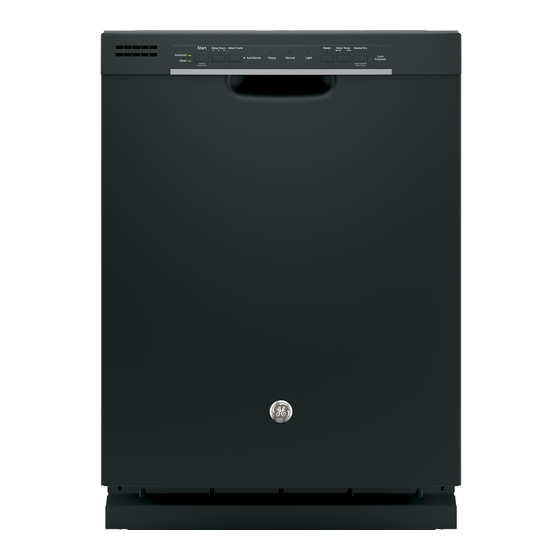
Models:
GDF520P
DO
GDF540H
DO
Parts Included:
This kit includes all parts needed for all models
listed above.
°
U I Board (User Interface)
WD21X10534
°
2 Vent Covers
°
Foam Strip (black in color)
°
Door Harness wire tie (may not be needed)
°
Installation
InstructionsWD00X1021
Tools You Will Need:
•
1/4" Nutdriver
•
T15Torx
scredriver
•
Hinge locking tool (see service guide 31-9226)
Step 3 - Remove complete Door
assembly
°
Consult
Service Guide 31-9226
or Mini-manual
for door removal
process.
°
A new wire tie for the door wire harness is
included
in the kit. Should the original tie
become damaged,
it must be replaced.
Step 4 - Separate the Door
°
Consult
Service Guide 31-9226
or Mini-manual
for door separation
process.
GE Appliances
General Electric Company
Louisville, KY 40225
WD00X1021
Advertisement

Subscribe to Our Youtube Channel
Related Manuals for GE GDF520P DO


Summary of Contents for GE GDF520P DO
- Page 1 GE Appliances Installation Instructions Dry Enhancement WD35X10395 February 2013 Dishwasher Dry Performance Step I - Remove Power from the Dishwasher Verify proper heater operation, check for error codes in diagnostic error mode, including Step 2 - Remove Inner Door Vent...
- Page 2 Step 5 - Remove Front Control Remove Console protective tape from the • Consult Service Guide 31-9226 or Mini-manual bottom of the for console removal process. foam strip. Step 6 - Remove Vent Conduit Place the strip inside the bottom of the vent area of the console.
Need help?
Do you have a question about the GDF520P DO and is the answer not in the manual?
Questions and answers