Table of Contents
Advertisement
NETWORK COMPASS USER MANUAL
CONTENTS
GENERAL INTRODUCTION TO B&G NETWORK.........................................................2
INTRODUCTION TO NETWORK COMPASS.................................................................3
COMPASS DISPLAY UNIT.............................................................................................4
EXAMPLE SYSTEMS USING NETWORK COMPASS...................................................4
INITIAL POWER-UP........................................................................................................5
SETTING THE DISPLAY BACK LIGHTING ...................................................................6
THE OFF COURSE DISPLAY.........................................................................................7
SETTING THE COURSE MEMORIES ............................................................................8
THE XTE DISPLAY .........................................................................................................9
THE RUDDER DISPLAY...............................................................................................10
THE HEAD/LIFT DISPLAY ...........................................................................................11
USING THE TIMER .......................................................................................................12
SETTING THE TIMER ...................................................................................................13
ENABLING/DISABLING THE TIMER BEEPS ..............................................................13
ENABLING THE OFF COURSE ALARM......................................................................14
SETTING THE COMPASS DAMPING ..........................................................................14
SETTING THE COMPASS OFFSET .............................................................................15
SETTING THE VARIATION ..........................................................................................15
SETTING THE DISPLAY FOR TRUE OR MAGNETIC READINGS .............................16
ENABLING THE HEAD/LIFT MODE.............................................................................16
SELECTING THE DISPLAY MODE ..............................................................................17
CALIBRATING THE COMPASS ...................................................................................17
OPERATION WITH AUTOPILOTS ...............................................................................18
TROUBLESHOOTING ..................................................................................................19
INSTALLATION ............................................................................................................20
SITING THE FLUXGATE ..............................................................................................21
INSTALLATION DATA..................................................................................................22
SPECIFICATIONS.........................................................................................................23
1
Advertisement
Table of Contents

Summary of Contents for B&G Network Network System
-
Page 1: Table Of Contents
NETWORK COMPASS USER MANUAL CONTENTS GENERAL INTRODUCTION TO B&G NETWORK............2 INTRODUCTION TO NETWORK COMPASS..............3 COMPASS DISPLAY UNIT.....................4 EXAMPLE SYSTEMS USING NETWORK COMPASS...........4 INITIAL POWER-UP......................5 SETTING THE DISPLAY BACK LIGHTING ..............6 THE OFF COURSE DISPLAY..................7 SETTING THE COURSE MEMORIES ................8 THE XTE DISPLAY ......................9 THE RUDDER DISPLAY....................10 THE HEAD/LIFT DISPLAY ...................11 USING THE TIMER .......................12... -
Page 2: General Introduction To B&G Network
This Network provides a comprehensive navigational system. Screened cables combined with the latest technology provide protection from interference between units and other systems. The Network system is continuously expanding your options and currently consists of the following units: INSTRUMENTS... -
Page 3: Introduction To Network Compass
NETWORK COMPASS USER MANUAL INTRODUCTION TO NETWORK COMPASS The Network COMPASS unit uses the latest advances in electronics and magnetic fluxgate technology to display a true or magnetic heading, as well as Off Course, Cross Track Error (XTE)*, Rudder Angle* and Head/Lift information on an easy to read Liquid Crystal Display (LCD). -
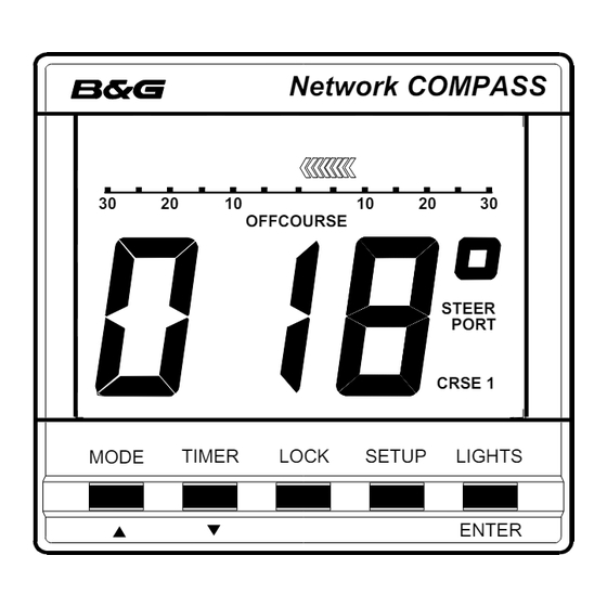
Page 4: Compass Display Unit
NETWORK COMPASS USER MANUAL COMPASS DISPLAY UNIT Network COMPASS OFFCOURSE STEER PORT CRSE 1 TIMER LOCK SETUP LIGHTS MODE ENTER EXAMPLE SYSTEMS USING NETWORK COMPASS Up to four COMPASS units can be connected to the system. Only one of these should be linked to a fluxgate and set to transducer mode, the others must be set to repeater mode. -
Page 5: Initial Power-Up
NETWORK COMPA SS USER MANUAL In this configuration the COMPASS unit is set to transducer mode and will send heading data to the other instruments. The other Network units are also transmitting data that the COMPASS may be able to use. For example, if the COMPASS is set to Head/Lift mode the wind angle data will cause it to switch between port and starboard tacks automatically. -
Page 6: Setting The Display Back Lighting
NETWORK COMPASS USER MANUAL SETTING THE DISPLAY BACK LIGHTING The Network COMPASS display back light has three brightness settings or off. Pressing the LIGHTS key cycles through these in the following order: • L 0 OFF • L 3 High •... -
Page 7: The Off Course Display
NETWORK COMPASS USER MANUAL THE OFF COURSE DISPLAY Pressing the MODE key will cycle the display between Off Course, Cross Track Error plus (XTE) if a Network GPS is fitted, Rudder angle if a Network PILOT is fitted and the Head/Lift display (if enabled). -
Page 8: Setting The Course Memories
NETWORK COMPASS USER MANUAL SETTING THE COURSE MEMORIES Whilst in Off Course mode the two course memories may be set. The currently active course memory is shown by the legend CRSE1 or CRSE2. Network COMPASS Network COMPASS OFFCOURSE OFFCOURSE STEER STEER PORT STBD... -
Page 9: The Xte Display
NETWORK COMPASS USER MANUAL THE XTE DISPLAY plus REQUIRES A GPS ON THE NETWORK. The Cross Track Error display is used to indicate how far the vessel is from the intended track (from waypoint to waypoint). Network COMPASS STEER PORT TIMER LOCK SETUP... -
Page 10: The Rudder Display
NETWORK COMPASS USER MANUAL THE RUDDER DISPLAY REQUIRES B&G NETWORK PILOT IN CIRCUIT. The rudder display indicates the current angle of the rudder, which is particularly useful on wheel steered boats. Network COMPASS RUDDER MODE TIMER LOCK SETUP LIGHTS ENTER The vessel is turning to starboard, the display shows the current heading and the rudder scale is visible beneath the bar graph which points to port, the direction to turn the wheel to straighten the rudder. -
Page 11: The Head/Lift Display
NETWORK COMPASS USER MANUAL THE HEAD/LIFT DISPLAY THE HEAD/LIFT PAGE HAS TO BE ENABLED IN THE SETUP MENU before it can be displayed. Network COMPASS Network COMPASS Network COMPASS Network COMPASS HEAD HEAD LIFT LIFT PORT PORT STBD STBD MODE TIMER LOCK SETUP... -
Page 12: Using The Timer
NETWORK COMPASS USER MANUAL USING THE TIMER Pressing the TIMER key enters the timer display mode, which is shown by the presence of a flashing colon. Network COMPASS MODE TIMER LOCK SETUP LIGHTS ENTER The timer can be set to any required value to a maximum time period of 99 hours 59 minutes. -
Page 13: Setting The Timer
NETWORK COMPASS USER MANUAL SETTING THE TIMER 1. Press TIMER to enter timer mode. 2. Press SETUP to give the display h:xx (xx represents a two digit number) the h will be flashing. 3. Press ENTER and the numbers will flash. 4. -
Page 14: Enabling The Off Course Alarm
NETWORK COMPASS USER MANUAL ENABLING THE OFF COURSE ALARM Ensure that the instrument is not in Timer mode. 1. Press SETUP until the OFFCOURSE legend flashes to indicate the alarm set up display. This value is preset to 0° which is shown as OFF. 2. -
Page 15: Setting The Compass Offset
NETWORK COMPASS USER MANUAL SETTING THE COMPASS OFFSET The compass offset compensates for fixed errors in the compass after installation and calibration. For example, the sensor orientation may not be exactly correct. 1. Press SETUP until a bearing is displayed and the degrees sign is flashing. 2. -
Page 16: Setting The Display For True Or Magnetic Readings
NETWORK COMPASS USER MANUAL SETTING THE DISPLAY FOR TRUE OR MAGNETIC READINGS 1. Press SETUP until TRUE is flashing and either ON or OFF is displayed. 2. Press ENTER. ON or OFF will flash. 3. Press the keys to switch the setting between ON and OFF 4. -
Page 17: Selecting The Display Mode
NETWORK COMPASS USER MANUAL SELECTING THE DISPLAY MODE 1. Press SETUP until a flashing t and either r or t is displayed. 2. Press ENTER. r or t will flash. 3. Press the keys to switch the setting between repeater (r) and transducer (t). 4. -
Page 18: Operation With Autopilots
COMPASS is used as a data repeater. However, the system will operate normally with the Pilot accepting data from the COMPASS unit. Only one fluxgate is required per Network system. If a backup fluxgate is connected to the COMPASS, it will override the PILOT's fluxgate if the COMPASS unit is set to transducer mode. -
Page 19: Troubleshooting
NETWORK COMPASS USER MANUAL TROUBLESHOOTING PROBLEM POSSIBLE CAUSE Display fails to light up Power not connected. Supply not 10 to 16 Volts. Data is not repeated from Network Compass not in repeater mode. Cables not correctly fitted. Compass fails to calibrate (-F-) Calibration manoeuvre performed badly. -
Page 20: Installation
NETWORK COMPASS USER MANUAL INSTALLATION The display heads are supplied with a clip-in mounting bracket which allows for easy installation. Access from behind is not necessary to secure the unit in place. However, to prevent theft and permanently fix the unit in position, locking studs and thumb nuts are supplied. -
Page 21: Siting The Fluxgate
NETWORK COMPASS USER MANUAL SITING THE FLUXGATE Mount the unit upright on a flat vertical bulkhead where it will be: • A safe distance from external magnetic interference: 1m/3ft from VHF, RDF, loudspeakers, depth sounders, engines, or power cables carrying heavy current •... -
Page 22: Installation Data
NETWORK COMPASS USER MANUAL INSTALLATION DATA 110.0mm 25.0mm 65.0mm Network COMPASS 110.0mm MODE TIMER LOCK SETUP LIGHTS ENTER Locking stud fixing Fluxgate Remote button Network connector Network & Power connector Rubber Gasket Mounting bracket 82.0mm Fit the gasket around the mounting bracket Bulkhead 82.0mm Gasket... -
Page 23: Specifications
NETWORK COMPASS USER MANUAL SPECIFICATIONS PHYSICAL PARAMETERS Display Backlit Liquid Crystal Display Dimensions 110 x 110 x 26 mm; 4.25 x 4.25 x 1" A space of 65 mm (2.6") is required behind the bulkhead for the display barrel. ENVIRONMENTAL -10 to +55 °C, +14 to +131°F @ 93% RH Operating Temp -25 to +70 °C, -13 to +158 °F @ 95% RH...
Need help?
Do you have a question about the Network System and is the answer not in the manual?
Questions and answers