
Summary of Contents for MCP CQ5010B
- Page 1 CQ5010B SINGLE TRACE 10MHZ OSCILLOSCOPE USER’S MANUAL ⎯⎯⎯⎯⎯⎯⎯⎯⎯⎯⎯⎯⎯⎯⎯⎯⎯⎯⎯⎯⎯⎯⎯⎯⎯⎯⎯⎯⎯⎯⎯⎯⎯⎯ CONTENTS ⎯⎯⎯⎯⎯⎯⎯⎯⎯⎯⎯⎯⎯⎯⎯⎯⎯⎯⎯⎯⎯⎯⎯⎯⎯⎯⎯⎯⎯⎯⎯⎯⎯⎯ 1. SAFETY PRECAUTION 2. SPECIFICATIONS 2.1 VERTICAL SYSTEM 2.2 TRIGGER SYSTEM...
-
Page 2: Table Of Contents
5 . ACCESSORIES 1. SAFETY PRECAUTION CQ5010B is a portable Oscilloscope with frequency bandwidth of 0~10 MHz and sensitivity of 5mV/DIV~5V/DIV. Equipped with 10:1 probe which makes the sensitivity up to 50V/div. Sweep rate at 0.1S/DIV ~ 0.1µS/DIV on horizontal system. The oscilloscope is easy to operate, and highly reliable. -
Page 3: Specifications
OS-10V 02/04/2001 Rev.2 Non compliance with the warnings and/or the instructions for use may damage the instrument and/or its components or injure the operator. Take extreme care for the following conditions when using the instrument : For your own safety and that of the instrument, you must follow the procedures described in this instruction manual and especially read all the notes preceded by the symbol carefully Do not use this instrument in a location where there is explosive gas in the vicinity. -
Page 4: Horizontal System
OS-10V 02/04/2001 Rev.2 2.3 HORIZONTAL SYSTEM 0.1S / DIV ~0.1µS / DIV ±3% Sweep Time Trimming Ratio 2.5:1 2.4 X-Y MODE Sensitivity 0.2V/DIV~0.5V/DIV Bandwidth(-3dB) DC: 0~1MHz AC: 10Hz~1MHz 2.5 CALIBRATION SIGNAL Waveform Symmetric Square Wave 05.V ±2% Range 1kHz ±2% Frequency 2.6 CRT 8 ×... -
Page 5: Control And Indicators
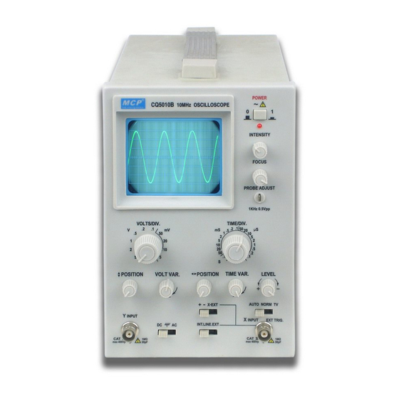
OS-10V 02/04/2001 Rev.2 3. CONTROL AND INDICATORS 3.1 Control Panel Position 3.1.1 Front Panel Fig 3-1 POWER 10MHz HANDY OSCILLOSCOPE INTENSITY FOCUS PROBE ADJUST 1kHz 0.5Vpp VOLTS/DIV. POSITION VOLT VAR. POSITION TIME VAR. LEVEL X EXT AUTO NORM TV Y INPUT INT. -
Page 6: Functions Of Control Switches
OS-10V 02/04/2001 Rev.2 3.2 FUNCTIONS OF CONTROL SWITCHES NO. SWITCHES FUNCTIONS POWER SWITCH Power on/off. POWER LIGHT Lights when power on. INTENSITY Controls brightness of display. FOCUS After obtaining appropriate brightness with INTENSITY, adjust FOCUS for clearest line. CALIBRATION Provide symmetric square wave for 0.5V range, frequency=1KHz. - Page 7 OS-10V 02/04/2001 Rev.2 3.3.1 VOLTAGE CHECKING CQ5010B oscilloscope use 220V ±10% voltage. Before using, make sure that the correct voltage is being used. Otherwise, it would cause accident and damage to the instrument. 3.3.2 BASIC OPERATION (1) POSITION FOR CONTROL SWITCHES...
- Page 8 OS-10V 02/04/2001 Rev.2 (3) X-Y OPERATION: When [10] set at EXT/X, The oscilloscope is used for X-Y operation, at this moment Input [18] is Y-axis with the same sensitivity, Input [13] as X-axis, [14] can be adjusted continuously within 0.2V/DIV~0.5V/DIV. 3.3.4 TRIGGER SOURCE In Fig 3-1, [12] provides 3 sources for selection, INT trigger EXT trigger input from [13], LINE input from power source.
- Page 9 OS-10V 02/04/2001 Rev.2 (3) Connect CH1 10:1 probe to input terminal, and connect with “CAL”. (4) Follow Chapter 3 to operate relative components, get waveform on the screen as figure 4.1 (5) Observe whether the waveform compensation is good, if not , you can adjust the LF compensation components as shown in figure 4-2 4.2 MEASUREMENT 4.2.1 P-P Voltage Measurements...
- Page 10 OS-10V 02/04/2001 Rev.2 probe is 2V/DIV, then Vp-p=2×4.1=8.2(V) Fig 4-3 4.2.2 DC VOLTAGE MEASUREMENT STEP: (1) Setup front panel connector to obtain a sweep baseline on the screen. (2) Setup input coupling options as “⊥”. (3) Setup POSITION, let sweep baseline coincide with horizontal center, define it as zero reference level.
-
Page 11: Time Measurements
OS-10V 02/04/2001 Rev.2 4.3 TIME MEASUREMENTS 4.3.1 TIME SPACE MEASUREMENTS This is a procedure for making time (period) measurements between two points on a waveform: (1) Connect the signal to be measured to the input terminal [18]. (2) Adjust level to obtain steady waveform. (3) Turn VAR clockwise to the calibration position, and set sweep controls to obtain a normal display of 1-2 signal cycles. - Page 12 OS-10V 02/04/2001 Rev.2 For rise time and fall time measurements, the 10% and 90% amplitude points are used as starting and ending reference points. (1) Apply a signal to the input jack [18]. (2) Use the VOLTS/DIV and VAR controls to adjust the waveform peak to peak height to five divisions.
- Page 13 OS-10V 02/04/2001 Rev.2 There are some cases which X axis requires control from external signals, e.g. external connection of sweep signals, signals of Lissajous pattern or other equipment’s display setup. X-Y mode operation is turn [10] to EXT/X, input signals through [13], sensitivity to be adjusted directly with [14], then input Y signal through [18].
Need help?
Do you have a question about the CQ5010B and is the answer not in the manual?
Questions and answers