Advertisement
MICROWAVE HOOD COMBINATION
INSTALLATION INSTRUCTIONS
This product is suitable for use above electric or gas cooking products up to and including 36" (91.4 cm) wide. See "Installation
Requirements" section for further notes.
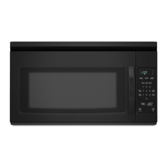
These installation instructions cover different models. The appearance of your particular model may differ slightly from the illustration in
these installation instructions.
Table of Contents
MICROWAVE HOOD COMBINATION SAFETY .............................. I
INSTALLATION REQUIREMENTS................................................... 2
Tools and Parts............................................................................... 2
Remove Cardboard Template........................................................ 2
Location Requirements................................................................... 2
Product Dimensions ....................................................................... 3
Electrical Requirements.................................................................. 3
INSTALLATION INSTRUCTIONS..................................................... 4
Remove Mounting Plate................................................................. 4
Rotate Blower Motor....................................................................... 4
Locate Wall Stud(s)......................................................................... 6
Mark RearWall................................................................................ 7
Drill Holes in RearWall.................................................................... 7
Attach Mounting Plate to Wall........................................................ 8
Prepare Upper Cabinet................................................................... 8
Install DamperAssembly ................................................................ 9
Install the Microwave Oven ............................................................ 9
Complete Installation.................................................................... 10
VENTING DESIGN SPECIFICATIONS............................................ 1 1
ASSISTANCE ................................................................................... 12
Replacement Parts ....................................................................... 12
Accessories................................................................................... 12
MICROWAVE HOOD COMBINATION SAFETY
Your safety and the safety of others are very important.
We have provided many important safety messages in this manual and on your appliance. Always read and obey all safety
messages.
This is the safety alert symbol.
This symbol alerts you to potential hazards that can kill or hurt you and others.
All safety messages will follow the safety alert symbol and either the word "DANGER" or "WARNING."
These words mean:
You can be killed or seriously injured if you don't immediately
follow
instructions.
You can be killed or seriously injured if you don't follow
instructions.
All safety messages will tell you what the potential hazard is, tell you how to reduce the chance of injury, and tell you what can
happen if the instructions are not followed.
W10247296B
Advertisement
Table of Contents

Related Manuals for Amana AMV2175CW0


Summary of Contents for Amana AMV2175CW0
-
Page 1: Table Of Contents
MICROWAVE HOOD COMBINATION INSTALLATION INSTRUCTIONS This product is suitable for use above electric or gas cooking products up to and including 36" (91.4 cm) wide. See "Installation Requirements" section for further notes. These installation instructions cover different models. The appearance of your particular model may differ slightly from the illustration in these installation instructions. -
Page 2: Installationrequirements
INSTALLATIONREQUIREMENTS t'O0_S 3_J Tools Needed The cardboard piece from the top of the microwave oven packaging is perforated. The piece inside the perforation is for use Gather the required tools and parts before starting installation. as a rear wall template. Read and follow the instructions provided with any tools listed here. - Page 3 Installation Dimensions NOTE: The grounded 3 prong outlet must be inside the upper cabinet. See "Electrical Requirements" section. |2" (30.5 crn) rain. (35.6 cm) max. iupper cabinet ii _] _iside cabinet depth Electrical Shock Hazard Plug into a grounded 3 prong outlet. 30"...
-
Page 4: Installationinstructions
INSTALLATIONINSTRUCTIONS 4. Lift blower motor out of microwave oven. Depending on your model, the mounting plate may be in the foam packaging, or it may be attached to the back of the microwave oven. NOTE: To avoid possible damage to the work surface, cover the work surface. - Page 5 Roof Venting Installation Only 6. Reattach blower motor to back of microwave oven with 1. Repeat Step 1 from "Wall Venting Installation Only." 2 screws removed in Step 3 of "Wall Venting Installation Only." 2. Repeat Step 2 from "Wall Venting Installation Only." Securely tighten screws.
- Page 6 NOTE: Ifnowall s tuds exist w ithin t hecabinet opening, donot 1. Using a studfinder, locate theedges o fthewall s tud(s) within install themicrowave oven. theopening. See illustrations in"Possible Wall S tud Configurations." 2. Mark thecenter ofeach stud, a nd draw a plumb l ine down each stud center.
-
Page 7: Locate Wall Stud(S)
5. With the support tabs facing forward (see illustrations in "Locate Wall Stud(s)" section), align the mounting plate center markers to the centerline on the wall, making sure its bottom The microwave oven must be installed on a minimum of 1 wall edge is aligned to the horizontal line drawn in Step 3, and that stud, preferably 2, using a minimum of 1 lag screw, preferably 2. -
Page 8: Drill Holes In Rearwall
6. Check alignment of mounting plate, making sure it is level. Installation for Wall Stud at One End Hole (Figure 3) 7. Securely tighten all lag screws and bolts. 1. Drill a 3/16" (5 mm) hole into the wall stud at the end hole Wall Stud at One End Hole (Figure 3) marked in Step 3 of "Mark Rear Wall."... - Page 9 5. Cut the 11/2"(3.8 cm) diameter hole at the circular shaded area "G" on the template. This hole is for the power supply cord. NOTE: If upper cabinet is metal, the supply cord bushing needs to be installed around the supply cord hole, as shown. Excessive Weight Hazard Use two or more people to move and install microwave oven.
- Page 10 NOTE: Ifmicrowave oven does notneed tobeadjusted, skip 2. Connect vent to damper assembly. steps 7-9. 7. If adjustment isrequired, rotate m icrowave oven downward. Using 2 ormore people, liftmicrowave oven offofmounting plate, a nd setaside o nacovered surface. 8. Loosen m ounting plate screws. Adjust mounting plate and retighten screws.
-
Page 11: Venting Design Specifications
VENTING DESIGN SPECIFICATIONS This section is intended for architectural designer and Rectangular to Round Transition builder/contractor reference only. NOTE: The minimum 3" (7.6 cm) clearance must exist between NOTES: the top of the microwave oven and the rectangular to round transition piece so that the damper can open freely and fully. -
Page 12: Assistance
Recommended Vent Length A 31/4 '' x 10" (8.3 x 25.4 cm) rectangular or 6" (15.2 cm) round vent 6" (15.2 cm) vent system = 73 ft (22.2 m) total should be used. The total length of the vent system including straight vent, elbow(s), transitions and wall or roof caps must not exceed the equivalent of 140 ft (42.7 m) for either type of vent.
Need help?
Do you have a question about the AMV2175CW0 and is the answer not in the manual?
Questions and answers