Table of Contents
Advertisement
Advertisement
Table of Contents

Related Manuals for G-Mouse ZYM-GM11-5U

Summary of Contents for G-Mouse ZYM-GM11-5U
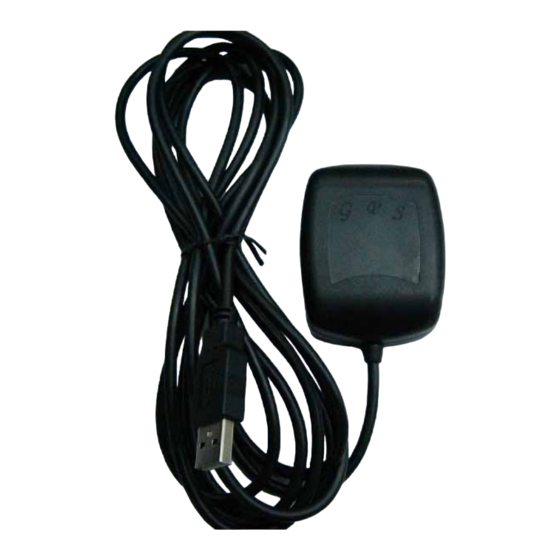
- Page 1 G-Mouse GPS Receiver ZYM-GM11-5U User Manual...
-
Page 2: Table Of Contents
2.1 Initialization setup 2.2 Navigation 3. Hardware Specification 3.1 Outline 3.2 Output connector 3.3 Magnetic plate(Concurrently fixed stand) 4. G-Mouse USB Driver 4.1 System requirement 4.2 Install USB driver 4.3 Verify the driver installation 5.Warranty 6. Trouble Shooting Guide 6.1 Satellite signal problem... - Page 3 6.2 Position fixing problem 6.3 GPS not fix problems. 7. AppendixA Software Protocol A.1 NMEA transmited message A.2 RTCM received data 8. AppendixB Coordinate System and Output Settings . B.1 Coordinate system B.2 Output settings...
-
Page 4: Usage Notice
Please do not expose this device to sun for a long time to avoid damage to internal precision circuit. Quick Start Check the package Standard pack ZYM-GM11-5U (GPS receiver, including magnet pad), disc (including quick use manual) -
Page 5: Introduction
With low power consumption, the G-Mouse tracks up to 12 satellites at a time, re-acquires satellite signals in 1 sec and updates position data every second. Features G-Mouse provides a host of features that make it easy for integration and use. -
Page 6: Technical Specification
1. Use the most advantage GPS module, the module got high performance CPU inside(ARM CPU), allow users to design different applications, store in the module, to provide the most economic solution for anybody. 2. High performance receiver tracks up to 12 satellites. 3. - Page 7 4) Humidity 1.3.3 Electrical Characteristics 1) Input voltage: +4.95~+5.5V DC 2) Backup battery: 3V Rechargeable Lithium cell battery. 1.3.4 Performance 1) Tracks up to 12 satellites. 2) Update rate: 1 second. 3) Acquisition time (average) Hot start: 8 second Warm start: 38 second Cold start: 48 second 4) Position accuracy: Position: <10m 90%...
-
Page 8: Operational Characteristics
After a position fix has been calculated, valid position and time information will be transmitted over the output channel(s). The G-Mouse utilizes initial data such as last stored position, data and time as well as satellite orbital data to achieve maximum acquisition performance. -
Page 9: Navigation
2) Failure of the internal memory battery without system standby power. Navigation After the acquisition process is complete, the G-Mouse will begin sending valid navigation information over its output channels. These data include: 1) Latitude/longitude/altitude 2) Velocity 3) Date/time 4) Error estimates... -
Page 10: Magnetic Plate(Concurrently Fixed Stand)
Magnetic plate (Concurrently fixed stand) The magnetic plate, a standard equipment, has been put in the G-Mouse base on delivery, can be put on the car roof, the boat roof or the other brace and face to the sky. 4 G-Mouse USB Adapter Driver... - Page 11 3) Please follow the screen guide and click “Finish” to complete. Maybe it is necessary to reboot PC, please reboot as it says. 4) Insert the G-Mouse USB connector into any empty USB slot, now your PC will recognize the USB device automatically. You may use the...
-
Page 12: Verify The Driver Installation
Verify the Driver Installation Please identify the COM port ID after you install the G-Mouse USB driver: 1) Click [Start], [Setup], and click the [Control Panel]. 2) While the windows of [Control Panel] shows up, double click the [System], [Hardware] and click the button [Device Manager]. Expend the tree node [Ports(COM&LPT)], you should see the item [Prolific... -
Page 13: Warranty
Warranty The G-Mouse is warranted to be free from defect in materials and functions for one year from the date of purchase. Any failure of this product within the period under normal conditions will be replaced at no charge to the customers. This warranty does not cover failures due to abuse, misuse, accident, or unauthorized alteration or repairs, inappropriate disassemble. - Page 14 Buildings near by, GPS signal interfered. Inside the forest, lots of covers above, GPS signal level down. If you use G-Mouse inside the car, some sun-control film will makes the GPS signal low or lost. GPS satellite is owned by America army, sometimes they will tune-down the accuracy by some reason.
-
Page 15: Position Fixing Problem
Position Fixing Problem The position fix problem below does not mean the G-Mouse GPS receiver s malfunction: You are driving on the freeway, but the GPS navigation software shows you are on the road beside. Or the opposite situation. You are driving on a grid like lane, it is possible to show your car on an incorrect lane, if these 2 lane very near. -
Page 16: Gps Not Fix Problems
Please wait few minutes more. GPS position fix may cost several minutes. Please make sure that you put the G-Mouse GPS receiver at a proper place. Some sun-control film for car may cutoff the satellite signal. You may replace it and try again. Please make sure that you are not inside of somewhere the GPS signal shaded. - Page 17 Table A-1 NMEA-0183 Output Messages A.1.1 Global Positioning System Fix Data (GGA) Samples:$GPGGA,161229.487,3723.2475,N,12158.3416,W,1,07,1.0,9. 0,M, , , ,0000*18 Table A-2 GGA Data Format...
- Page 18 Table A-3 Position Fix Indicator A.1.2 Geographic Position - Latitude/Longitude (GLL) Samples: $GPGLL,3723.2475,N,12158.3416,W,161229.487,A*2C Table 1-4 GLL Data Format A.1.3 GNSS DOP and Active Satellites (GSA) Samples: $GPGSA,A,3,07,02,26,27,09,04,15, , , , , ,1.8,1.0,1.5*33 Table A-5 GSA Data Format...
- Page 19 *1 Satellite used in solution. Table A-6 Mode 1 Table A-6 Mode 2 A.1.4 GNSS Satellites In View (GSV) Samples: $GPGSV,2,1,07,07,79,048,42,02,51,062,43,26,36,256,42,27,27,138, 42*71 $GPGSV,2,2,07,09,23,313,42,04,19,159,41,15,12,041,42*41...
- Page 20 Table A-8 GSV Data Format NOTE: Item <4>,<5>,<6> and <7> repeat for each satellite in view to a maximum of four (4) satellite per sentence. Additional satellites in view information must be sent in sentences. These fields will be null if unused. A.1.5 Recommended Minimum Specific GNSS Data (RMC) Samples: $GPRMC,161229.487,A,3723.2475,N,12158.3416,W,0.13,309.62,12059...
- Page 21 A.1.6 Course Over Ground and Ground Speed (VTG) Samples: $GPVTG,309.62,T, ,M,0.13,N,0.2,K*6E Table A-10 VTG Data Format Note *1:All "course over ground" data are geodetic WGS84. A.1.7 Time & Date (ZDA)
-
Page 22: Rtcm Received Data
Samples: $GPZDA,114523.62,12,04,2001,10,34*6E Table 1-11 ZDA Data Format A.2 RTCM Received Data The default communication parameters for DGPS Input are 9600 baud. 8 data bits, stop bit, and no parity, Position accuracy of less than 5 meters can be achieved with the GPS CF card receiver by using Differential GPS (DGPS) real-time pseudo-range correction data in RTCM SC-104 format, with message type 1,5 or 9. -
Page 23: Output Settings
B.2 Output Settings Coordinate System: WGS84 Baud rate: 9600 Output message: GGA, GLL, GSA, GSV, RMC, VTG , ZDA...
Need help?
Do you have a question about the ZYM-GM11-5U and is the answer not in the manual?
Questions and answers