Advertisement
Advertisement

Summary of Contents for Ampro XA1000
- Page 1 XA1000 & XA1400 INSTALLATION AND OPERATION MANUAL...
-
Page 2: Important Safety Information
Do not parallel- or series-connect an amplifi er output with any other amplifi er output. Australian Monitor Inc is not 7. Always operate the unit with the AC ground wire connected to the responsible for damage to loudspeakers for any reason. -
Page 3: Table Of Contents
INTRODUCTION AND CONTENTS INTRODUCTION Congratulations on choosing Australian Monitor for your professional amplifi cation requirements. FEATURES The design of our XA Series Audio Power Amplifi ers embraces all the aspects of a well designed amplifi er. The visual design, mechanical,... -
Page 4: Features
> Suppression of inrush current at mains turn-on > Input muting at turn-on > Input overvoltage protection > Radio-frequency interference suppression > Short-circuit protection and indication > High overload mains breaker > Thermal sensing PAGE 4 XA1000 & XA1400 INSTALLATION AND OPERATION MANUAL... -
Page 5: Controls, Connectors & Indicators
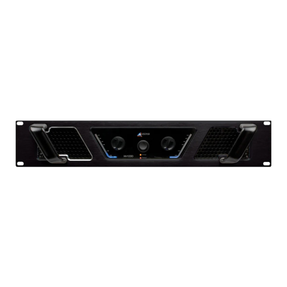
> complex or very low loads > over driving the amplifi er The Australian Monitor Installations Series logo will illuminate and indicates that the amplifi er is on and receiving mains power. It should be noted that the minimum load for the amplifi er is 2 ohms per channel (4 ohm bridged). - Page 6 See the installation section of this manual for detailed information on speaker connector wiring. PAGE 6 XA1000 & XA1400 INSTALLATION AND OPERATION MANUAL...
-
Page 7: Installation
1 (input ground), either by linking the pins in the input Pin 1+ = Bridge Output Positive connector or by the source equipment’s output wiring. Pin 2+ = Bridge Output Negative XA1000 & XA1400 INSTALLATION AND OPERATION MANUAL PAGE 7... - Page 8 (i.e. a steel shield) should help. Earth loops can arise from the interfacing of the various pieces of equipment and their connections to various safety earths. PAGE 8 XA1000 & XA1400 INSTALLATION AND OPERATION MANUAL...
-
Page 9: Operation
After two seconds this mute will release, allowing any applied signal to pass un-attenuated. When switching the amplifi er off, wait a couple of seconds before switching the amplifi er on again. This allows the ICS circuit to reset. XA1000 & XA1400 INSTALLATION AND OPERATION MANUAL PAGE 9... -
Page 10: Maintenance
You should periodically remove the dust and keep the grille clean. Removal of dust from the rear grille will also aid cooling. SPEAKER CONNECTOR (BRIDGE) PAGE 10 XA1000 & XA1400 INSTALLATION AND OPERATION MANUAL... -
Page 11: Specifications
Both channels driven, 2ohm load, 230Vac 1/8th power 3.8A Dimensions (H x W x D) 88mm x 482mm x 400mm Weight 9.5 Kg Shipping Dimensions (H x W x D) 190mm x 600mm x 560mm Shipping Weight 12kg XA1000 & XA1400 INSTALLATION AND OPERATION MANUAL PAGE 11... - Page 12 AUSTRALIA AND NEW ZEALAND www.australianmonitor.com.au SYDNEY MELBOURNE BRISBANE ADELAIDE PERTH AUCKLAND (SA & NT SALES) (NSW & ACT SALES) (VIC & TAS SALES) (QLD SALES) (WA SALES) (NZ SALES) 1 Clyde Street 22/277 42 Commercial Road 31 Walsh Street 3/11 Howe Street 9C Piermark Drive Silverwater Middleborough Road...

Need help?
Do you have a question about the XA1000 and is the answer not in the manual?
Questions and answers