Table of Contents
Advertisement
OWNER'S
MANUAL
ASSEMBLY
INSTALLATION
OPERATION
REPAIR PARTS
MODEL NUMBERS
BJ90 AND SJ125
CANADIAN MODELS
BJ90-C AND SJ125-C
Read Rules and Instructions
Carefully for Safe Operation
IMPORTANT:
Installation must be made in
accordance with State and
Local Ordinances which may
differ from this Installation
Manual.
ALPHA AMERICAN CO., 10 INDUSTRIAL BLVD., PALISADE, MN 56469
SUPER JACK & BIG JACK
CAUTION:
www.yukon-eagle.com
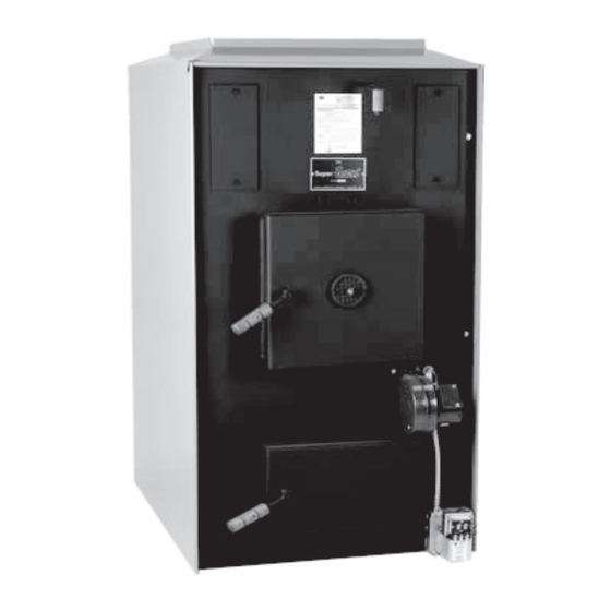
BIG JACK
MODEL BJ90
WOOD BURNING FURNACES
SUPER JACK
MODEL SJ125
Advertisement
Table of Contents

Related Manuals for Yukon SJ125

Summary of Contents for Yukon SJ125
- Page 1 WOOD BURNING FURNACES CAUTION: Read Rules and Instructions Carefully for Safe Operation IMPORTANT: Installation must be made in accordance with State and Local Ordinances which may differ from this Installation Manual. ALPHA AMERICAN CO., 10 INDUSTRIAL BLVD., PALISADE, MN 56469 www.yukon-eagle.com...
-
Page 2: Electrical Connections
FOR YOUR SAFETY: FOR YOUR SAFETY: If you smell gas: 1. Open windows Do not store or use gasoline or 2. Do not touch electrical switches other flammable vapors and 3. Extinguish any open flame liquids in the vicinity of this or 4. -
Page 3: Table Of Contents
TABLE OF CONTENTS INTRODUCTION Safety Statements........................2, 4-6 Unpacking and Inspection.........................7 Features and Benefits of SJ125.....................8, 9 Features and Benefits of BJ90 ....................10, 11 BJ90 Specifications ........................12 SJ125 Specifications ........................13 PLAN YOUR INSTALLATION Plan your Installation ........................14 Locating the Furnace ........................15 Clearances to Combustibles ......................15... -
Page 4: Safety Statements
Safety Statements SAVE THESE INSTRUCTIONS STOP FOR SAFETY! Safe assembly, operating and maintenance practices should always be followed whenever using any equipment. Wherever you see the caution sign, extra safety precautions should be taken. You must stop, read, and carefully follow the safety instructions before proceeding. READ THROUGH THE ENTIRE MANUAL It is recommended to read through the entire manual before beginning your installation and/or operating your furnace. - Page 5 Safety Statements CAUTION INSPECT FLUE PIPES, FLUE PIPE JOINTS, AND FLUE PIPE SEALS REGULARLY TO ENSURE THAT SMOKE AND FLUE GASES ARE NOT DRAWN INTO, AND CIRCULATED BY, THE AIR- CIRCULATION SYSTEM. CAUTION THE WARM-AIR SUPPLY OF THE SUPPLEMENTARY FURNACE SHALL NOT BE CONNECTED TO THE COLD-AIR RETURN DUCTING OF THE CENTRAL FURNACE.
-
Page 6: Safety Statements 2
Safety Statements TO THE INSTALLER It is necessary to ensure that there is sufficient air flow through each furnace after the add- on installation has been completed. It is suggested that the temperature rise method be used since most installers are likely to have the necessary equipment. The temperature measurements may be made using a potentiometer and thermocouples, mercury thermome- ters. -
Page 7: Unpacking And Inspection
Unpack and Check your Cartons INSPECT SHIPMENT Note any damage to the shipping cartons. Remove all items from your shipping cartons. Check all items against the packing list below. Note any items lost or damaged in shipment. Refer to the exploded view and parts list in the back of the manual for the part names and numbers of missing or damaged items. -
Page 8: Features And Benefits Of Sj125
Furnace Features - SJ125 FORCED DRAFT COMBUSTION FAN AND LIMIT CONTROL BLOWER The fan limit control turns the fan on This furnace operates on a forced draft and off. It works off of temperature principle. When the thermostat is call-... - Page 9 Furnace Features - SJ125...
-
Page 10: Features And Benefits Of Bj90
Furnace Features - BJ90 FAN AND LIMIT CONTROL EASY ACCESS ASH PAN The fan limit control turns the fan on Designed to allow for easy removal of and off in furnace applications. It ashes. Pulls out of furnace, equipped works off of temperature and also pro- with additional cross bar handle for vides a high temperature safety limit. - Page 11 Furnace Features - BJ90...
-
Page 12: Bj90 Specifications
Specifications BIG JACK 90 MODEL BJ90 BTU Capacity......................90,000 Wood Capacity....................5.25 Cu. Ft Heat Exchanger (Total Area)................19 Sq. Ft Maximum Wood Length....................24” Fire Box Dimensions............16” wide x 24” long x 23” high Smoke Collar........................6” Weight........................595 lbs Height...................... -
Page 13: Sj125 Specifications
Specifications SUPER JACK 125 MODEL SJ125 BTU Capacity......................125,000 Wood Capacity......................5.25 Cu. Ft. Heat Exchanger (Total Area)...................24.5 Sq. Ft. Maximum Wood Length.......................24” Fire Box Dimensions..............16” wide x 24” long x 23” high Smoke Collar.........................7” Weight...........................645 lbs Height..........................47” Width..........................26.25” Depth..........................34.5” Warm Air Plenum Opening...................22” x 20”... -
Page 14: Plan Your Installation
Plan Your Installation PLAN YOUR INSTALLATION It is recommended to read through the entire manual before beginning your installation. Follow all steps exactly. Reading this manual will also help you get all the benefits from your furnace. CAUTION: Read these rules and the instructions carefully. -
Page 15: Locating The Furnace
Plan Your Installation LOCATING THE FURNACE Locate the furnace as close to the chimney or flue as possible. The furnace should be located no more than 10 feet away from the chimney. You will need 1” rise per linear foot of pipe as a minimum. -
Page 16: Typical Installations
Plan Your Installation • ‚ TYPICAL INSTALLATIONS • SERIES ADD-ON ‚ PARALLEL ADD-ON ƒ INDEPENDENT INSTALLATION IMPORTANT DUCTS AND PLENUMS SHALL BE CONSTRUCTED ENTIRELY OF SHEET METAL. ƒ... -
Page 17: Proper Chimneys
Plan Your Installation PROPER CHIMNEYS The National Fire Protection Association (NFPA) requires that all factory built chimneys be Listed and installed in accordance with conditions of the Listing in the manufacturers instructions. NFPA also requires that your chimney extend at least three (3) feet above the highest point when it passes through the roof and at least two (2) feet higher than any portion of the building within ten (10) feet of the chimney. -
Page 18: Furnace Located In Confined Space
Plan Your Installation FURNACE LOCATED IN CONFINED SPACE When the furnace is in utility room, install two open grilles. Place them in a wall or door opening to the rest of the house. One grille will supply combustion air. Locate it near the floor. The other grille is for ventilation. Locate it close to the ceiling. -
Page 19: Combustion Air (Make Up Air)
Plan Your Installation COMBUSTION AIR Make-up outside air must be provided to furnace for proper fuel combustion. This is provided by openings to outside of building. These openings shall have unobstructed areas not less than the areas of the flue pipe. -
Page 20: Installation
Installation PLACE FURNACE Review all instructions in the Planning Your Installation section. Place the furnace in the pre-selected location. Refer to Page 15 in the Plan Your Installation section. Make sure the furnace is level. Furnace Casing The furnace casing is shipped unassembled in a carton attached to the furnace. - Page 21 Installation CANADIAN FURNACES ONLY Front panel installation: (SJ125-C) All Jack furnaces that are shipped to Canada will With firing door open, pull damper rod all the way include an insulated front panel casing and an out. Slide panel casing on by tilting and maneuver- insulated back panel casing.
-
Page 22: Combustion Blower
Installation Combustion Blower Remove the three (3) self tapping screws off the front of the furnace. (Set aside) Line up the gasket to the mounting flange of the combustion blower and using the 3 screws, tighten onto the front of the furnace. See Fig. -
Page 23: Fan And Limit Control
Installation INSTALLING THE HONEYWELL FAN/LIMIT CONTROL Included in the accessory carton is a white sheet metal bracket that is 8-1/4 inches high and 3-1/4 inches wide. It has a 7/8” hole in it 6 inches from the bottom. Right below the 7/8” hole are 2 screw holes. This bracket also has 2 screw mounting holes on the bottom 1-1/4 inch flange. -
Page 24: Mounting Thermostat
Installation MOUNTING THE THERMOSTAT The thermostat must be mounted on an interior centrally located wall. Place it away from direct sunlight, drafts, and approximately 5 feet above the floor. It is not required that it is level. Place it right next to your thermostat for your existing furnace. -
Page 25: Electrical Wiring
Installation ELECTRIC WIRING All electrical wiring must be done in accordance with the National Electrical Code. The code needs to be legally authorized in the area where the installation is being made. The circuit protector device must be located in a convenient place near the furnace. - Page 26 Wiring Diagram EXISTING FURNACE COMBUSTION BLOWER HONEYWELL DIGITAL ADD-ON FURNACE THERMOSTAT BLOWER (Jack Furnace) FAN AND LIMIT CONTROL Rc R Y C W G INTERLOCK EXISTING FURNACE BLOWER JUMPER TRANSFORMER TRANSFORMER RELAY BACK VIEW COIL INDICATES TRANS-RELAY TERMINALS INDICATES THERMOSTAT TERMINALS TRANSFORMER RELAY FRONT VIEW...
-
Page 27: Wiring Diagram
Wiring Diagram Wiring for 4-SPEED - 1/4 HP MOTOR (OPTIONAL) BROWN/WHITE BROWN WHITE COMMON BLACK (HIGH) YELLOW (MED HIGH) ORANGE (MED LOW) INSULATE UNUSED SPEED TAP LEADS SEPARATELY RED (LOW) GREEN GROUND ROTATION-SHAFT END BLACK WHITE WHITE BLACK BLACK BLACK WHITE WHITE OPTIONAL 3 WIRE CONNECTION... -
Page 28: Connecting Smoke Pipe
Installation CONNECTING SMOKE PIPE Set the smoke pipe end of the furnace as close to the chimney as possible. For every foot of lateral pipe, the rise of the smoke pipe toward the chimney must be at least one inch. Do not exceed 10 feet in length and no more than 2 elbows. -
Page 29: Barometric Draft Regulator
Installation INSTRUCTIONS FOR INSTALLING FIELD CONTROLS TYPE R-C BAROMETRIC DRAFT CONTROL DO NOT ATTACH DRAFT CONTROL TO TOP OR BOTTOM OF THE FLUE PIPE, NOR IN A ROOM SEPARATED FROM THE FURNACE. BEST LOCATION IS AS CLOSE TO FURNACE AS POSSIBLE. IMPORTANT A MANOMETER MUST BE USED TO ACCURATELY ADJUST FLUE DRAFT... - Page 30 Installation DRAFT CONTROL INSTALLATION Insert the draft control in the open end of the stub. Revolve it so it is right-side-up and imprinting on control reads normally. See Fig. 9 To function properly, the draft control must be mounted level and plumb in the tee joint stub. Using a carpenter’s spirit level placed vertically across the ring, position the draft control so it is plumb and does not lean forward or backward.
- Page 31 Installation SETTING THE DRAFT REGULATOR AND SOME INFORMATION ON CREOSOTE TO FUNCTION PROPERLY AND SAFELY, it is impera- CREOSOTE BUILD UP - Creosote, in a vaporized state, tive that the draft control when installed in the Tee stub, is present in the gases emitted by burning wood and is is pointing away from surrounding walls or obstructions.
-
Page 32: Best Wood To Burn
Operating Instructions BEST WOOD TO BURN All solid fuel, whether it is coal, pine, oak or any grain has about 12,000 BTU's per pound if its moisture content is zero. Wood that has been cut, split and air dried for 2 years has about 8,000 usable BTU's per pound. -
Page 33: Helpful Hints
Operating Instructions HELPFUL HINTS Set the draft to proper setting. The chimney, hook-ups, and kinds of wood will be a factor. Open the disc on the side of the Draft Inducer Motor (supplied with your Jack furnace) to allow air into the furnace for combustion. -
Page 34: Wood Firing The Furnace
Operating Instructions STARTING A WOOD FIRE MANUAL DRAFT 1. Place several pieces of crumpled paper in the center of SPINNER your firebox. In a criss-cross pattern, place a couple hand- fuls of dry kindling wood 3/4” thickness, then several small dry pieces of firewood. -
Page 35: Burning Coal
Operating Instructions OPERATING INSTRUCTIONS FOR BURNING COAL ON 1/2-INCH OPENING GRATES (Optional) The following instructions are for burning various types of coal, storage of coal, and the cleaning of the furnace. Some coal is oil-treated at the mine. Some users have indicated that it tends to make the coal difficult to start. -
Page 36: Burning Coal
Operating Instructions WHAT SIZE COAL SHOULD I BURN? The air space between the furnace grates is 1/2 inch. Therefore, coal smaller than 1/2 inch can fall through the grates into the ash pan. • Pea size coal ranges from 9/16 to 11/16 inch. •... -
Page 37: Ash Removal
Maintenance ASH REMOVAL When burning wood, every morning when there is just a bed of hot embers, run your poker over top of grates making sure grate slots are clear of burnt fuel. Once every week or two, depending on how much fuel you burn, ashes should be removed. -
Page 38: Faulty Chimney And Draft Problems
Maintenance FAULTY CHIMNEY AND/OR DRAFT PROBLEMS - CAUSES AND CURES A sound chimney system is imperative, especially when burning wood. Indoor chimney, either masonry or type “HT” metal chimneys are the best. Because warm air rises, a warm chimney allows the smoke and other by-products of combustion a natural exit up and out the chimney. - Page 39 Maintenance TOP OF CHIMNEY LOWER THAN SURROUNDING OBJECTS REMEDY: EXTEND CHIMNEY ABOVE ALL OBJECTS WITHIN 30 FEET CHIMNEY CAP PUSHED OVER FLUE OR FLUE OBSTRUCTED BY A VENTILATOR REMEDY: REMOVE OBSTRUCTION ACCUMULATION OF SOOT OR DEBRIS IN OFFSET REMEDY: REMOVE AIR LEAKS THROUGH CRACKS IN FLUE AND CHIMNEY DISCLOSED BY SMOKE TEST...
-
Page 40: Cleaning Chimney, Smoke Pipe And Heat Exchanger
Maintenance 1. At the start of the heating season... Ÿ It is advisable to have your local furnace profes- sional inspect and service your furnace for the coming heating season. Ÿ The furnace, smoke pipe and chimney should be cleaned and checked for repairs. 2. - Page 41 Notes...
-
Page 42: Super Jack (Sj125)
Exploded Views & Parts List SUPER JACK - SJ125... -
Page 43: Super Jack (Sj125)
10110001 Junction Box Transformer/Relay (Honeywell) 10111100 Conduit 10113200 Straight Conduit Connector 10113300 90 Degree Conduit Connector 10108700 Honeywell Interlock Relay 310-1 Insulated Front Panel (SJ125-C only) 311-1 Insulated Back Panel (SJ125-C only) 10108400 Honeywell Digital Thermostat * Items not shown... -
Page 44: Big Jack (Bj90)
Exploded Views & Parts List BIG JACK - BJ90... -
Page 45: Big Jack (Bj90)
Exploded Views & Parts List BIG JACK - BJ90 Key No. Part No. Description Jacket (Top) Jacket Side (Right) Firebrick (9 x 4-½ x 1-¼) 19-1/2 Smoke Flap Assembly Grate Fillers Heavy Duty Cast Iron Grate Draft Inducer Gasket Draft Inducer Fire Door Gasket Fire Door &... -
Page 46: Service Hints & Troubleshooting
SERVICE HINTS & TROUBLESHOOTING Main blower vibrating when in use... POSSIBLE CAUSE SOLUTION Loose allen screw on squirrel cage Tighten the allen screw, be sure squirrel cage did not move to one side or the other. Defective motor or blower bearings Return motor or blower for a replacement. - Page 47 POSSIBLE CAUSE SOLUTION Improper draft Measure draft with gauge. Should be set at .03 Water Column. (SJ125 Only: Pull out damper handle when load- ing. Chimney cap too close to top of chimney Remove and discard chimney cap. Too long of run of smoke pipe from Jack to chimney Relocate Jack closer to chimney.
-
Page 48: Your Notes
Notes... - Page 49 Notes...
- Page 50 Notes...
- Page 51 Notes...
- Page 52 CAUTION: Read Rules and Instructions Carefully for Safe Operation IMPORTANT: Installation must be made in MODEL SJ125-C accordance with State and Local Ordinances which may differ from this Installation Manual. ALPHA AMERICAN CO., 10 INDUSTRIAL BLVD., PALISADE, MN 56469 www.yukon-eagle.com...
Need help?
Do you have a question about the SJ125 and is the answer not in the manual?
Questions and answers