
Related Manuals for Spa Builders SC-CF-SBD


Summary of Contents for Spa Builders SC-CF-SBD
- Page 1 CLEARLY ADVANCED SPA SYSTEMS! ™ WNER'S MANUAL SC-CF-SBD SPA SYSTEMS INSTALLATION, INSTRUCTIONS & MORE! TAKING OVER THE WAVES!
-
Page 2: Table Of Contents
Contents Topics covered in this manual are as follows: Warnings Warning instructions General Information Safety instructions Specifications General specifications Electrical & temperature specifications Keypad dimensions Power box dimensions Installation Keypads • K-18 • K-19 Overlays Power box Connecting • your pack to your spa •... - Page 3 Notes: SC-CF-SBD Owner’s Manual...
-
Page 4: Warnings
• The electrical load of connections to this control must not exceed the ratings specified by Spa Builders Systems Group Inc. Failure to ensure compliance with proper electrical load specifications may cause hazardous operating conditions and/or decreased the life span of the control. - Page 5 • Do not connect any equipment to this control other than equipment and or accessories that are specified or approved by Spa Builders Systems Group Inc. for each output. • This control should always be installed with the proper ori- entation as per the specifications provided by Spa Builders Systems Group Inc.
- Page 6 Make sure that the pressure switch setting is adequate for your application. • Should you have any questions with respect to any of the foregoing or the reference materials mentioned herein, please do not hesitate to contact us. SC-CF-SBD Owner’s Manual...
- Page 7 Notes: SC-CF-SBD Owner’s Manual...
-
Page 8: General Information
National Electrical Code and any state, province or local electrical codes in effect at the time of the installation. Important RISK OF ELECTRICAL SHOCK! If used with 120V, your pack must be connected only to a grounded receptacle. SC-CF-SBD Owner’s Manual... - Page 9 Notes: SC-CF-SBD Owner’s Manual...
-
Page 10: Specifications
• Current limiting option • Freeze protection • Temperature measurement within 1 F From keypad • Temperature set point • Temperature display in C or F • Spa light control (on/off) • One or two-speed pump control SC-CF-SBD Owner’s Manual... -
Page 11: Electrical & Temperature Specifications
Specifications Electrical Specifications Input 240 V, 48 A, 60 Hz 120 V, 15 A, 60 Hz Outputs (high) 120 V, 14 FLA / 80 LRA Pump 1 (low) 120 V, 14 FLA / 80 LRA or (high) 240 V, 14 FLA / 80 LRA (low) 240 V, 14 FLA / 80 LRA Connector: J&J or AMP... -
Page 12: Keypad Dimensions
K-18 " Dual pump system 5" Single pump with blower system Single pump system K-19 " 7" Single pump system Dual pump system Single pump with blower system SC-CF-SBD Owner’s Manual... -
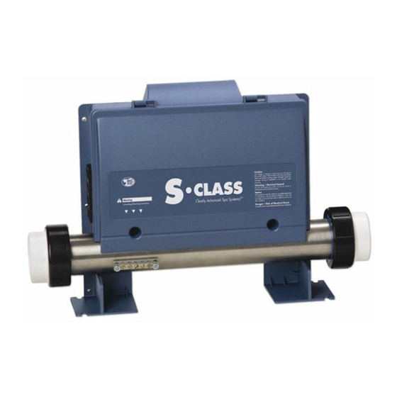
Page 13: Power Box Dimensions
Hinged Cover The cover of the power box can be easily opened to access the connection ports. Simply remove the 2 front cover screws and pull the hinged cover up to access main board, connectors and jumpers. SC-CF-SBD Owner’s Manual... -
Page 14: Installation
Insert the keypad and secure it in place by pressing firmly on the keypad. Note: If the keypad is physically damaged, the spa must not be used and the keypad should be replaced immediately. SC-CF-SBD Owner’s Manual... - Page 15 Insert the keypad and secure it in place by pressing firmly on the keypad. Note: If the keypad is physically damaged, the spa must not be used and the keypad should be replaced immediately. SC-CF-SBD Owner’s Manual...
-
Page 16: Overlays
Pump & Blower systems Installation T o properly install an overlay on a keypad, you only need a hair dryer, paper towel and rubbing alcohol. First, peel off the plastic film that protects the LED display window. SC-CF-SBD Owner’s Manual... - Page 17 Make sure the overlay is well aligned and rests perfectly in the recess of the keypad. Insure that the overlay is properly glued by pressing with your finger over the entire surface. SC-CF-SBD Owner’s Manual...
-
Page 18: Power Box
Four holes located on the pack feet can be used to fix it to the floor. Front view Bottom view Holes for floor-mounting Holes for wall-mounting Warning: Any physical damage to the enclosure arising from misuse, abuse or improper installation will automatically void any liability of the product. SC-CF-SBD Owner’s Manual... -
Page 19: Your Pack To Your Spa
Plumbing connections must be made with the tail pieces at both ends of the pack's heater and must be perfectly sealed. Refer to your spa manual for more information on how to properly seal your plumbing connections. SC-CF-SBD Owner’s Manual... -
Page 20: Keypad & Probe
Clearance between Low and High Voltage conductors must be at least 1/4". Connecting the The water temperature probe must be similarly Temperature connected to the power Probe box, with cable following the same route as the main keypad. SC-CF-SBD Owner’s Manual... -
Page 21: Optional Wet-End Fitting
3) Tighten the stopper nut to ensure proper sealing. 4) Apply foam on the back of the fitting to prevent cold or warm air from affecting the sensor reading. SC-CF-SBD Owner’s Manual... -
Page 22: Jumpers
Single pump (single pump K-18 or K-19 overlays) Position 2: Dual pump or single pump and a blower (dual pump system K-18 or K-19 overlays) Note: It is mandatory that the topside overlay matches the settings of this jumper SC-CF-SBD Owner’s Manual... - Page 23 Notes: SC-CF-SBD Owner’s Manual...
-
Page 24: Output Connectors
Your pack also comes with a light socket that is ready to Pump 1 receive a lamp. Pump 2/blower Pump 2/blower Pump 1 Ozone Pack with Pack with J&J connectors Amp connectors SC-CF-SBD Owner’s Manual... -
Page 25: Pump 1
2) Using a pair of long-nose pliers, unplug the white wire of the pump 1 connector from the board. (P7) 3) Reconnect the white wire to the P18 (connec- tor) and make sure the connector is properly inserted. SC-CF-SBD Owner’s Manual... - Page 26 1) Turn the breaker off. 2) Locate the Pump 1 connectors. (P12 and P14) 3) Using a pair of long- nose pliers, invert the connection of the black and red wires. Make sure the connectors are properly inserted. SC-CF-SBD Owner’s Manual...
-
Page 27: Blower
5) Reconnect the three wires on the board at the follow- ing locations Black= P11 Green= P6 White= P9 for a 120V blower P17 for a 240V blower Make sure they are properly inserted. SC-CF-SBD Owner’s Manual... -
Page 28: Pump 2 / Blower
Blower) 2) Using a pair of long-nose pliers, unplug the white wire of the Pump 2 (or blower) connector. 3) Reconnect the white wire to the P17 connector and make sure the connector is properly inserted. SC-CF-SBD Owner’s Manual... -
Page 29: Ozonator
(P8) from the board. 3) Reconnect the white wire to P19 (see wiring drawing). Make sure the connector is properly inserted. Note: The ozonator will be activated only during the filter cycle. SC-CF-SBD Owner’s Manual... -
Page 30: Electrical Wiring
Warning: Total current ouput • cannot exceed total current input rating! For 240 vac systems: White Black Green Electrical Box GFCI Pack Terminal Block For 120 vac systems: White x White Black Green x Jumper supplied with the pack SC-CF-SBD Owner’s Manual... -
Page 31: Powering Your Pack
If you are not using a conduit for the power cable: 1) Remove the strain relief. 2) Connect the wires to the terminal block. 3) Install the strain relief and make sure it holds the cable firmly in place. SC-CF-SBD Owner’s Manual... -
Page 32: With Conduit Adaptor
Powering the pack If you are using a conduit for the power cable: 1) Remove the strain relief. 2) Install the conduit adaptor. 3) Bring the 4 wires to the pack and connect them to the terminal block. SC-CF-SBD Owner’s Manual... - Page 33 Notes: SC-CF-SBD Owner’s Manual...
-
Page 34: Instructions
The first press of Light key will turn light on. A second press will turn light off. The light will automatically shut itself off after 2 hours. K-18 & K-19: The "Light" indicator is displayed when light is on. SC-CF-SBD Owner’s Manual... - Page 35 The "Heater" indicator will flash if there is a request for more heat but the heater has not started yet. Water Temperature The 3-digit LED display shows the water temperature reading. Display The reading will be refreshed every second. SC-CF-SBD Owner’s Manual...
- Page 36 Note that after a power failure, the filter cycle duration will return to its default value (6 hours, twice a day). In this case, the first filter cycle will start 12 hours after power has been restored. SC-CF-SBD Owner’s Manual...
-
Page 37: Dual Pump Or Pump & Blower Systems
Pump 1 is display when Pump 2 or running. blower is running. K-19: The "Pump 1" triangular icon will appear on the display when Pump 1 is running. SC-CF-SBD Owner’s Manual... - Page 38 The first press on Light key will turn light on. A second press will turn light off. The light will automatically shut itself off after 2 hours. The "Light" indicator is displayed when light is on. SC-CF-SBD Owner’s Manual...
- Page 39 The "Heater" indicator or icon will flash if there is a request for more heat but the heater has not started yet. Water Temperature The 3-digit LED display shows the water temperature reading. Display The reading will be refreshed every second. SC-CF-SBD Owner’s Manual...
- Page 40 Note that after a power failure, the filter cycle duration will return to its default value (6 hours, twice a day). In this case, the first filter cycle will start 12 hours after power has been restored. SC-CF-SBD Owner’s Manual...
-
Page 41: Alarms
The "Heater" indicator is flashing when pump is on at high speed. Not a bug but a feature! The system is turning the heater off when pump is in high speed to limit the amount of electrical current drawn. SC-CF-SBD Owner’s Manual... -
Page 42: Error Conditions
109˚F. Call your dealer or service supplier if problem persists. The display is flashing. A power failure has occurred. Press any key to stop the flashing and reprogram your filter cycle. SC-CF-SBD Owner’s Manual... - Page 43 Notes: SC-CF-SBD Owner’s Manual...
-
Page 44: Wiring Diagram
120v 240v White / 0 VAC Black / 12 VAC Green / Ground Black / Line Red / Line Heater White / Com Black 1 Black 2 Jumper Settings Pressure Switch Refer to page 10 Black Black SC-CF-SBD Owner’s Manual... -
Page 45: Factory Default Settings
Heaters - 240V= 4Kw Heater - 120V= 1Kw Heater J&J - J&J color connector for pump 2, 1 speed connector installed - Additional J&J color Blower connector plug also supplied - Water temperature at 95ºF Set Point SC-CF-SBD Owner’s Manual... - Page 46 CLEARLY ADVANCED SPA SYSTEMS! ™ For more information about our spa packs and all our other products and services, visit our web site at www.sbsg-equipment.com Smart Winter Mode 1.866.NEW.SBSG 9919-100375-B 3-85-7022-B (1.866.639.7274)
Need help?
Do you have a question about the SC-CF-SBD and is the answer not in the manual?
Questions and answers