Table of Contents
Advertisement
A.O. Smith - Voltex™
Hybrid Electric
Heat Pump Water Heater
Installation
Instructions and
Use & Care Guide
To obtain technical, warranty or service assistance during or after
the installation of this water heater, call toll free
1-800-527-1953
When calling for assistance, please have the following
information ready:
1. Model number
2. 7 Digit product number
3. Serial number
4. Date of installation
5. Place of Purchase
Table of Contents
Water Heater Safety ............................................................................... 2
Installing Your Water Heater ................................................................. 3-9
Installation Checklist .............................................................................. 10
Operating Your Water Heater ........................................................... 11-13
Maintenance of Your Water Heater .................................................. 14-15
Diagnostic Codes .................................................................................. 16
Troubleshooting Chart ........................................................................... 17
Repair Parts Illustration ......................................................................... 18
Notes... .............................................................................................. 19-20
Consumer Information ................................................................ 3
Consumer Responsibilities ......................................................... 3
Unpacking Instructions ............................................................ 3-4
Location Requirements ............................................................... 4
Water System Piping ................................................................ 5-6
Temperature & Pressure Relief Valve ....................................... 7-8
Electrical Requirements ........................................................... 8-9
Before Using ............................................................................. 11
Water Temperature Regulation ................................................. 11
Adjusting the User Interface Module/ Operational Mode .......... 12
Operational Conditions ............................................................. 13
Temperature and Pressure Relief Valve .................................... 14
Draining and Flushing ................................................................ 14
Heating Element Replacement ............................................. 14-15
Cleaning the Heat Pump ........................................................... 15
Page
320506-000
November 2010
1
Advertisement
Table of Contents

Subscribe to Our Youtube Channel
Related Manuals for A.O. Smith Voltex


Summary of Contents for A.O. Smith Voltex
-
Page 1: Table Of Contents
A.O. Smith – Voltex™ Hybrid Electric Heat Pump Water Heater Installation Instructions and Use & Care Guide To obtain technical, warranty or service assistance during or after the installation of this water heater, call toll free 1-800-527-1953 When calling for assistance, please have the following information ready: 1. -
Page 2: Water Heater Safety
WATER HEATER SAFETY Your safety and the safety of others are very important. We have provided many important safety messages in this manual and on your appliance. Always read and obey all safety messages. This is the safety alert symbol. This symbol alerts you to potential hazards that can kill or hurt you and others. -
Page 3: Installing Your Water Heater
INSTALLING YOUR WATER HEATER Consumer Information elements, the more effi cient the unit will be. The tank capacity of this heat pump water heater is sized to This water heater should be installed in accordance with maximize the use of the heat pump to deliver hot water at the local code authority having jurisdiction, the power a lower cost as compared to heat pump waters with lower company or electric utility, and this installation manual. -
Page 4: Location Requirements
• Inspect all parts for damage prior to installation and IMPORTANT: The water heater should be located in an start-up. area where leakage of the tank, connections, condensate • Completely read all instructions before attempting to lines or condensate will not result in damage to the area adjacent to the water heater or to lower floors of the assemble and install this product. -
Page 5: Water System Piping
Water System Piping 3. Some local codes may require, and the manufacturer of this water heater recommends, installing a mixing Piping, fi ttings, and valves should be installed according to valve or an anti-scald device in the domestic hot water the installation drawing (Figure 4). -
Page 6: Condensate Drain Line Installation
Closed System/Thermal Expansion Please note the following: • The system should be installed only with piping that is suitable for potable (drinkable) water such as copper, CPVC, or polybutylene. This water heater must not be installed using iron piping or PVC water piping. Explosion Hazard •... -
Page 7: Temperature & Pressure Relief Valve
Temperature and Pressure exceed the marked maximum working pressure of the water heater. Install the valve into an opening provided and Relief Valve marked for this purpose in the water heater, and orient it or provide tubing so that any discharge from the valve exits only within 6 in. -
Page 8: Electrical Requirements
When making the electrical connections, always make sure: Figure 6 • The electrical service provides 240 VAC to the water heater T&P Relief Valve Insulation for proper operation. DO NOT use 208 VAC. • Wire sizes and connections comply with all applicable T&P Relief Valve Insulation codes or in the absence of local or state codes follow Canadian Electrical Code (CAN/CSA C22. -
Page 9: Insulation Blankets
5. Connect these two wires to the two wires on the water Figure 8A heater using wire nuts or other connectors. Junction Box 6. Connect the free ends of the two wires to the shut off Green switch on the condensate pump in accordance with the Ground manufacturers recommendations. -
Page 10: Installation Checklist
INSTALLATION CHECKLIST Water Heater Location Regulation” section). Condensate Drain Line Installation □ Centrally located with the water piping system. □ The fl ooring beneath the water heater must be able to □ Must be located with access to an adequate drain or support the weight of the water heater when fi... -
Page 11: Operating Your Water Heater
OPERATING YOUR WATER HEATER Water Temperature Regulation Before Using 1. Make sure the water heater has been properly WARNING installed. See “Installing Your Water Heater” section. 2. Make sure the air filter is correctly seated, as it may shift during shipping or installation. See “Repair Parts Illustration”... -
Page 12: Adjusting The User Interface Module/ Operational Mode
Adjusting the User Interface Module/Operational Modes Water Temperature Adjustment Other Controls The water temperature can be adjusted from 95°F (35°C) Lock - Holding this button for more than 3 (95°F) to 150F° (65.5°C). Use the Up and Down Buttons seconds switches the lock mode on or off. When on the front panel to set the desired the User Interface Module is locked a symbol temperature. -
Page 13: Operational Conditions
Operational Conditions Water Heater Sounds During the normal operation of the water heater, sounds or Powered Anode Operation noises may be heard. These noises are common and may result from the following: To shelter the glass-lined water tank from corrosion through electrolysis, this water heater is equipped with a 1. -
Page 14: Maintenance Of Your Water Heater
MAINTENANCE OF YOUR WATER HEATER Temperature and Pressure 5. Connect a hose to the drain valve and terminate it to an adequate drain or external to the building. Relief Valve 6. Open the water heater drain valve and allow all of the water to drain from the tank. -
Page 15: Cleaning The Heat Pump
Routine Preventive Maintenance Figure 12: At least monthly, a visual inspection should be made of the following: Wires • Air Filter (Remove and inspect, clean if needed, and reinstall). • Condensate drain pan and condensate lines. Element • The lower metal drain pan for standing water which may indicate a clogged condensate drain pan, condensate lines, or plumbing leak. -
Page 16: Diagnostic Codes
DIAGNOSTIC CODES DISPLAY SHOWS INDICATES CORRECTIVE ACTION UPPER ELEMENT Upper element is not Turn off power at the circuit breaker/fuse box and check for functioning a loose connection at the element. For access directions CONNECT see “Heating Element Replacement” section. If error persists FAULT proceed to the next step. -
Page 17: Troubleshooting Chart
DIAGNOSTIC CODES ELECTRONIC Indicates the power anode is Contact a qualified person to service the unit. not operating properly POWER ANODE ERROR #0-9 (# CAN BE 0-9) NOTE: The diagnostic codes listed above are the most common. If a diagnostic code not listed above is displayed, contact Residential Technical Assistance referencing the number on the front of this manual. -
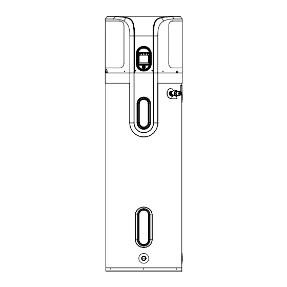
Page 18: Repair Parts Illustration
REPAIR PART ILLUSTRATION REPAIR PARTS LIST PARTS DESCRIPTION ITEM Upper Access Cover Lower Access Cover Upper Element (4500 Watts) Lower Element (2000 Watts) Energy Cut-Off (ECO) Switch Temperature & Pressure Relief Valve (T&P) Dip Tube (at hot water outlet) Powered Anode Rod User Interface Module Air Filter Air Inlet Side Panel... -
Page 19: Notes
NOTES... - Page 20 Copyright © 2010 A.O. Smith Corporation. All rights reserved.
- Page 21 réservés. droits Tous Corporation. Smith A.O. 2010 © Copyright...
- Page 22 NOTES...
- Page 23 pièce Description d’article Numéro produit. série modèle, Numéros suivants renseignements toujours donnez rechange, pièces commander moment 527-1953. composant rénovation, Centre distributeur, plombier, votre auprès commandées être peuvent rechange pièces ILLUSTRÉ RECHANGE PIÈCES module carte Fusibles marche Condensateur réservoir inférieure supérieure température Sonde décharge...
- Page 24 efficacité mode service pour qualifiée personne Contacter fonctionne chaleur à pompe routine diagnostic compléter pour minutes immédiatement environ prend chauffe-eau démarrage, premier démarre chauffe-eau AUTRE thermique fonctionne sécurité à décharge soupape Remplacer thermique sécurité à décharge Soupape » thermique échéant) réparer faire décharge.)
- Page 25 utilisateur. d’interface carte mère carte l’appareil. réparer pour qualifiée personne Contacter entre communication COMMUNICATION ERREUR ouverts. chaude d’eau robinets tous s’écoule l’air) interruption plein) (sans l’eau jusqu’à maison dans chaude (Réservoir réservoir. d’eau robinets tous Ouvrir complètement Remplir dans d’eau assez NIVEAU ALARME...
- Page 26 marche. mise avant diagnostic système à procédera chauffe-eau REMARQUE marche. chauffe-eau mettre pour interrupteur marche. mise avant minutes) (environ diagnostic bouton appuyer chauffe-eau courant Rétablir système à procédera chauffe-eau REMARQUE chauffe-eau. d’accès voulus. fonctionnement panneau fixer inspectés/nettoyés, été condensats mode d’eau température Régler...
- Page 27 sédiments. éliminer à façon l’eau à réservoir Rincer réservoir. complètement vider chauffe-eau vidange robinet Ouvrir bâtiment. l’extérieur à adéquat drain à aboutir faire vidange robinet tuyau Raccorder froide. d’eau d’entrée robinet Fermer chaude. plus soit l’eau jusqu’à proximité à chaude d’eau robinet Ouvrir...
- Page 28 brûlure. risque réduire pour chaude d’alimentation conduite recommandé anti-brûlure dispositif chaude. d’eau robinet sortie à l’eau température augmenter faire éventuelle conséquence pour occasion, chaque à brûleur l’allumage entraîne Ceci moins). gallons] litres (11,35 chaude d’eau quantité faible tire chaude d’eau robinet annulées.
- Page 29 réservoir. complètement vider temps, période longue pendant coupée être doit l’alimentation prolongées. périodes pour l’appareil à électrique l’alimentation couper fonctionner. faire pour électrique alimentation nécessite réservoir protégeant L’anode IMPORTANT vacance. bouton toucher suffit vacance, mode désactiver Pour vacance. bouton toucher suffit vacance, mode...
- Page 30 voulu. fonctionnement mode chauffe- régler oublier prolongé, séjour d’un retour REMARQUE froid. temps réservoir d’empêcher d’énergie pertes minimum réduire température, basse à l’eau maintenir permet réglage ». fonctionnement modes utilisateur d’interface module Réglage « section Voir vacance. mode chauffe-eau régler etc.), (vacances, période...
- Page 31 »). l’eau température Réglage « section (voir fabricant directives conformément installée échéant) mélangeuse Vanne □ consultation. pour chauffe-eau proximité à trouver doit » d’entretien »). thermique dilatation fermé d’utilisation guide d’installation Instructions « manuel □ circuit Système « section (voir fermé...
- Page 32 électrique service terre à Mise électrique terre Alimentation Vert Phase Vers inutile. thermique protection rendant accessoire, chaleur Noir perte thermique protection matière exigences Rouge pour nationalese normes dépasse répond chauffe- Votre stockage. réservoirs à chauffe-eau avec homologués Connecteurs lieu accessoire chaleur perte réduire...
- Page 33 l’installation. ». fonctionnement modes effectuer pour qualifié électricien d’un services retenir doit utilisateur d’interface module Réglage « section voir chauffe-eau, électrique câblage correctement installer fonctionnement modes tous détaillée description pour nécessaires compétences possède l’acheteur Pour chaude. d’eau distribution d’efficacité combinaison meilleure offre Hybrid...
- Page 34 indiquée prévue ouverture dans soupape Installer eau. chauffe- service pression dépassant maximale pression pour conçue être doit décharge soupape Cette chaude. à systèmes décharge soupapes portant courantes) (éditions Z21.22 ANSI normes avec conformité confirmer pour répertoriés matériaux d’équipements production périodiquement inspecte reconnu national...
- Page 35 ».) condensats à pompe Installation « section (voir s’active pompe dans flotteur à l’interrupteur fonctionne condensats à pompe où dans chaleur à pompe coupe dernier installée, condensats à pompe • PVC. sont condensats vidange conduites deux matériau composé chaleur à pompe vidange REMARQUE...
- Page 36 métallique. récupération dans condensats vidange conduites acheminer utilisée. être doit condensats à pompe condensats, vidange conduites pour disponible n'est adéquat drain Drain minimal int. diam. (3/4 maximal espace d’évacuation Conduite (Froid) d’arrêt Robinet ». thermique chauffe-eau. fermé/dilatation diamètre circuit d'un Système «...
- Page 37 d’évacuation Drain (967) litres véhicule (760) litres Arrêt (lb) Poids Capacité Tableau utilisée. soit rempli chauffe-eau poids supporter résidentiel garage capable plate-forme qu’une à Veiller po). 0,46 moins dans Installation d’au plancher partir à élevé inférieur l’élément manière Figure fasse chauffe-eau l’installation exiger...
- Page 38 efficace. sera l’appareil plus éléments, plutôt chaleur à pompe utilisant fonctionne l’appareil côté. d’installation souvent plus »). fonctionnement modes utilisateur pièces mettre chauffe-eau l’emballage Retirer • d’interface module Réglage « section (Voir demande. verticale. position dans stocké transporté être forte périodes pendant fonctionnent...
- Page 39 charge. niveau pour chaleur à pompe jaquette données plaque Consulter R-134a. réfrigérant utilise chauffe-eau chaleur à pompe IMPORTANT ouvert. où moment robinet proximité à nues ammes fl d’avoir fumer interdit s’écouler. à commence l’eau mesure à tuyau s’échappant l’air inhabituel probablement aura d’hydrogène,...
- Page 40 Lorsque 1-800-527-1953 frais sans composez chauffe-eau, l’installation après pendant l’entretien garantie à relatifs renseignements technique assistance obtenir Pour d’entretien d’utilisation guide d’installation Instructions chaleur à pompe à Chauffe-eau électrique Hybride Voltex – Smith A.O.
Need help?
Do you have a question about the Voltex and is the answer not in the manual?
Questions and answers