Table of Contents
Advertisement
Quick Links
Advertisement
Table of Contents

Subscribe to Our Youtube Channel
Summary of Contents for Televic Aladdin
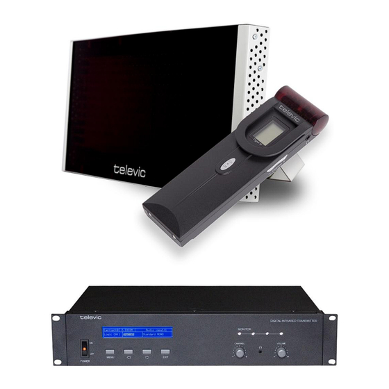
- Page 1 Aladdin Digital Infrared Language Distribution Installation and User Manual...
- Page 2 To protect your hearing avoid high pressure level on headphones. Adjust to a lower and convenient level. If any detailed information needed, please contact your local TELEVIC representative. TELEVIC is the registered trademark of TELEVIC N.V. Televic Conference Systems...
-
Page 4: Important Safety Instructions
Clean only with a dry soft 16. All TELEVIC products are guaranteed for 3 years cloth. excluding the following cases caused by 6. To prevent from any hazard use only... - Page 5 Aladdin Digital Infrared Language Distribution Installation and User Manual The lightning flash with an arrowhead symbol, with an Caution: equilateral triangle, is intended to To reduce the risk of electric shock, alert the user to the presence of DO NOT open covers, no useable uninsulated ‘dangerous voltage’...
-
Page 6: Table Of Contents
Aladdin Digital Infrared Language Distribution Installation and User Manual Content Introduction ........................9 1.1. Summary ........................10 1.2. System Technology ....................... 11 1.2.1. Basic System Concept ........................... 11 1.2.2. IR Radiation............................11 1.2.3. Signal Processing ..........................12 1.2.4. Audio Quality Modes ..........................13 1.2.5. - Page 7 Overview ........................59 6.2. View ..........................59 6.3. Charging Procedure ...................... 60 Fault Diagnosis ......................61 Technical Data ......................63 8.1. System Specification ..................... 63 8.2. Infrared Transmitters (Aladdin T8) ................65 8.3. Radiators and Accessories ..................... 66 Televic Conference Systems 2011-09-01...
- Page 8 Receivers, Headphones, Battery Packs, Charging Case ........... 67 8.4.1. Receivers (Aladdin R8) .......................... 67 8.4.2. Headphones ............................68 8.4.3. Ni-MH Rechargeable Battery Pack (Aladdin BP) ................... 68 8.4.4. Charging Case (Aladdin CHC) ........................ 68 8.5. Connection Details ......................69 8.5.1.
-
Page 9: Introduction
Installation and User Manual Introduction This manual describes the Televic Aladdin system: language distribution through digital Infrared. It gives a summary about the Aladdin series. It describes the system technology and gives the aspects of infrared distribution. Televic Conference Systems... -
Page 10: Summary
It uses both digital infrared audio transmitting and control technique dirATC and a Aladdin RAD25 25W digital infrared radiator special digital infrared chip. Aladdin can be used in Aladdin R8 8 channel digital infrared receiver simultaneous interpretation systems for multi- ... -
Page 11: System Technology
Figure 1.2: The basic system concept 1.2.2. IR Radiation Aladdin series audio signal is based on transmission by modulated infrared radiation. Infrared radiation is part of the electro-magnetic spectrum, which is composed of visible light, radio waves and other types of radiation. -
Page 12: Signal Processing
Aladdin Digital Infrared Language Distribution Installation and User Manual 1.2.3. Signal Processing Aladdin uses high frequency carrier signals (typically 2-6 MHz) to prevent interference by contemporary light sources. Fully digital audio processing (a) Digital infrared transmitter schematic guarantees a constant high audio quality. -
Page 13: Audio Quality Modes
The table below lists all possible channel combinations per carrier: Figure 1.4: Standard band of Aladdin infrared language distribution system Figure 1.5: Band allocation of BAND Televic Conference Systems 2011-09-01... - Page 14 2 x 10 kHz (left) and 2 x 10 kHz (right) 2 x 20 kHz 1 x 20 kHz (left) and 1 x 20 kHz (right) Remark : when Aladdin receivers are used in The available carrier frequencies are in combination with a transmitter of another...
-
Page 15: Aspects Of Infrared Distribution
Installation and User Manual 1.3. Aspects of Infrared 1.3.1. Ambient Lighting Distribution Aladdin can be operated without any problem even if fluorescent lamps (with or without electronic A good digital infrared language distribution system ballast or dimming facility) such as TL lamps or ensures that all delegates in a conference venue energy saving lamps are switched on. -
Page 16: Objects, Surfaces And Reflections
(glassy aimed directly towards a radiator. To minimize the or transparent appearance) objects. Both objects in disadvantage of this aspect, Aladdin R8 receiver the conference venue and structure of the walls and adopts an ingenious structural design with peculiar ceilings will influence the distribution of infrared 270°... -
Page 17: The Footprint Of The Radiator
Aladdin Digital Infrared Language Distribution Installation and User Manual 1.3.4. The Footprint of the Radiator The number of transmitted carriers and the output power of the radiator determine the coverage area of a radiator. The total radiation energy of a radiator is distributed over transmitted carriers. -
Page 18: Positioning The Radiators
Aladdin Digital Infrared Language Distribution Installation and User Manual If the path of the infrared signals is blocked, e.g. 1.3.5. Positioning the Radiators under balconies, at least one additional radiator is needed to cover the ‘shaded’ area (see Figure 1.13). -
Page 19: Overlapped Footprints And Multipath Effects
Aladdin Digital Infrared Language Distribution Installation and User Manual 1.3.6. Overlapped Footprints and Multipath Effects If footprints of two radiators overlap, the total coverage area may be larger than the sum of the two separate footprints. In an area with overlap... -
Page 21: Digital Infrared Transmitter
The Aladdin T8 is suitable for either tabletop or 19-inch menu and submenus are given in a tree structure rack mounting using. Four feet (for tabletop) and and there is an explanation on how to use the two brackets (for rack mounting) are supplied. -
Page 22: Installation
Aladdin Digital Infrared Language Distribution Installation and User Manual configuration. 2.2. Installation The following describes the rear view of the Aladdin T8 infrared transmitter. Transmitter can be fixed in a standard 19-inch cabinet. The transmitter is equipped with a pair of fixing brackets (1). -
Page 23: Connection
CPU5500 directly or via an AOP5500/9 or AOP2500 respectively. 2.3.2. To External Audio Sources Aladdin T8 transmitter has 8 channels audio inputs for connecting to external unbalanced audio sources (such as other brand conference systems) or for music distribution. -
Page 24: To Emergency Signal Switch
Aladdin Digital Infrared Language Distribution Installation and User Manual 2.3.3. To Emergency Signal Switch 2.3.4. To Another Transmitter To use the emergency function, fire alarm linked Bypass (master + bypass) mode trigger interface (normally open) must The transmitter can be operated in bypass mode to connected to the emergency switch connector. - Page 25 Aladdin Digital Infrared Language Distribution Installation and User Manual Combination (master + slave) mode Aladdin T8’s unique merging function can combine two N channels transmitters as one 2N channels system (maximum 16 channels). It can be achieved Note: by setting the transmitter which is connected to When a slave transmitter is radiator(s) to “Master”...
-
Page 26: Menu Structure
Aladdin Digital Infrared Language Distribution Installation and User Manual 2.4. Menu Structure Televic Conference Systems 2011-09-01... -
Page 27: Configuration And Operation
”EXIT” button “Monitor channel” and switch on the transmitter. B) Starting Initialization: Switch on Aladdin T8 transmitter. The current status of the transmitter will be displayed on the LCD screen: If status is “Master” mode (N) or (C) display shows: “Total Channels”... - Page 28 Aladdin Digital Infrared Language Distribution Installation and User Manual C) Accessing “Main” Menu: Press “Menu” button. Depending on transmitter status, display shows the terms: In “Master” mode : → “Network” → “Carrier” → “Channel name” → “Input sensitivity” → “Aux. input”...
-
Page 29: Network
Aladdin Digital Infrared Language Distribution Installation and User Manual 2.5.1. Network “Network” includes 3 submenus: → “IP Address” → “Subnet Mask” → “Gateway” 1) Setting Up Unique “IP Address” for the Transmitter: Use “/” button to switch between the four numbers ... -
Page 30: Carrier
Aladdin Digital Infrared Language Distribution Installation and User Manual 2) Channel Number Configuration 2.5.2. Carrier Press “MENU” button at this interface to go to channel number configuration, as shown in “Carrier” includes 4 submenus: figure below. → “Set up status”... -
Page 31: Channel Name
Aladdin Digital Infrared Language Distribution Installation and User Manual 4) Save Settings 2.5.3. Channel Name Use “MENU” button to save setting Go to next carrier configuration Assign a language name for every channel. Repeat above until all carriers have been set ... -
Page 32: Input Sensitivity
Aladdin Digital Infrared Language Distribution Installation and User Manual 2.5.4. Input Sensitivity 2.5.5. Aux Input “Aux Input” (Auxiliary audio input) includes 3 “Input sensitivity” includes 2 submenus: submenus: → “All” → “Aux Input Type” → “Per Input” → “Sensitivity” → “Play Music”... -
Page 33: Other
Aladdin Digital Infrared Language Distribution Installation and User Manual “Play Music” 2.5.6. Other If “Aux input type” is “Stereo music”, stereo or mono music from auxiliary audio input will be “Other” includes 5 submenus: distributed to all output channels. “MUSIC” will be displayed at this moment. - Page 34 Aladdin Digital Infrared Language Distribution Installation and User Manual “Test” Transmitter goes to test mode and testing tone will be distributed to all output channels. Use “MENU” button or “EXIT” button to stop test mode. “Int. Unit”...
-
Page 35: Monitor
Aladdin Digital Infrared Language Distribution Installation and User Manual 2.6. Monitor For testing the transmitter, the front panel has a monitoring facility including a monitor channel selector, a monitor headphone jack and a monitor volume control (refer to fig. 2.1). -
Page 37: Digital Infrared Radiator
8 audio distribution channels. Radiators This chapter describes the Aladdin RAD25 digital connected to the HF (BNC) connectors of the IR infrared radiator. transmitter. A maximum of 30 radiators, daisy chained connected, can be connected to each of these outputs. - Page 38 Aladdin Digital Infrared Language Distribution Installation and User Manual Aladdin RAD25 Rear View Aladdin RAD25 Side View Figure 3.2: Radiator (rear) 1. Output power switch 2. Signal input 3. Synchronous output interface Figure 3.3: Radiator (side view) 4. Power supply 5.
-
Page 39: Position Planning
Aladdin Digital Infrared Language Distribution Installation and User Manual 3.2. Position Planning 3.2.1. Rectangular Footprints For position planning, please read section 1.3 to To determine the optimal number of infrared understand and consider every aspect of infrared radiators needed to have complete coverage of a distribution. -
Page 40: Planning Radiators
Aladdin Digital Infrared Language Distribution Installation and User Manual 3.2.2. Planning Radiators Note The mounting height is the distance Plan the radiators by following procedure: from the reception level and not from 1. Define the positioning of the radiators by the the floor to the radiator. -
Page 41: Cabling
Aladdin Digital Infrared Language Distribution Installation and User Manual 3.2.3. Cabling Signal delay differences can occur because of the differences in the cable length from the transmitter to each radiator. In order to avoid the risk of black spots (see section 1.3.6), use equal cable length from transmitter to radiator if possible (see Figure 3.7). -
Page 42: Mounting
Aladdin Digital Infrared Language Distribution Installation and User Manual 3.3. Mounting 3.3.1. Mounting on a Floor Stand The radiator can be permanently installed on the Fix the bracket of the radiator into the top of the wall, under a ceiling or balcony by bracket. The floor stand with screw. -
Page 43: Wall Mounting
Aladdin Digital Infrared Language Distribution Installation and User Manual 3.3.2. Wall Mounting 3.3.3. Ceiling Mounting A separate bracket is optional for wall mounting The radiator can be fixed to the ceiling by using the (refer to Figure 3.10). The bracket can be fixed on to built-in bracket. -
Page 44: Connecting To Transmitter
Each one can connect This is usually done when full power output is not up to 30 Aladdin RAD25 radiators in daisy chain. The needed, e.g. when a portable system is used in a radiators are connected with RG-58 cables. The small venue. -
Page 45: Setting The Radiator Delay Switches
Take signal delay rate as 5.6 ns/m (value as delays can be set with the delay switch situated at example for calculation only, real value the side of the radiator. Aladdin T8 transmitter has depends on the cable type used) a digital display showing the current compensation ... - Page 46 Aladdin Digital Infrared Language Distribution Installation and User Manual 5. Divide the calculated signal delay difference by 25. The rounded off figure is the signal delay switch position for the radiator; 6. If applicable, add delay switch positions for radiators under a balcony, (see section 3.6.3);...
- Page 47 Aladdin Digital Infrared Language Distribution Installation and User Manual Table 3.1: Calculation of the cable signal delays Radiator Total cable Cable length Cable signal delay Signal delay Delay switch number length L(m) difference -L(m) per meter (ns/m) difference (ns) position...
-
Page 48: System With Two Or More Transmitters In One Room
Aladdin Digital Infrared Language Distribution Installation and User Manual 5. For each radiator calculate the signal delay 3.6.2. System with Two or More difference by subtracting the cable signal delay from the maximum signal delay Transmitters in One Room 6. Divide the signal delay difference by 25. The... - Page 49 Aladdin Digital Infrared Language Distribution Installation and User Manual Table 3.2: Calculation of the master-bypass signal delay Master-bypass transmitter Cable signal delay Master-bypass cable length per meter signal delay (ns/m) (ns) 50*5.6=280 Table 3.3: Calculation of the delay switch positions of a system with two transmitters...
-
Page 51: Digital Infrared Receiver
Installation and User Manual Digital Infrared 4.1. Overview Receiver Aladdin R8 IR receiver can receive up to 8 language channels. Both rechargeable Ni-HM battery and disposable battery can be used. The receiver is This chapter describes the Aladdin R8 digital equipped with channel selector, volume control, infrared receiver. - Page 52 Aladdin Digital Infrared Language Distribution Installation and User Manual 7. Volume control - An up/down switch to adjust the volume, the volume will be displayed on LCD. 8. Screw to fix the battery cover 9. Battery pack or disposable batteries...
-
Page 53: Operation
Aladdin Digital Infrared Language Distribution Installation and User Manual 4.2. Operation Note At the end of their technical lives both The receiver only works if an headphone is disposable batteries and battery packs connected and the receiver switches to stand-by should be discarded according to state. -
Page 54: Testing The Coverage Area
Aladdin Digital Infrared Language Distribution Installation and User Manual 4.3. Testing the Coverage 4.3.1. Reception Test Mode Area The receivers can be switched to test-mode to indicate the reception quality for each carrier. This chapter describes the testing of the coverage To activate the test-mode: push the channel are and the reception test mode. -
Page 55: Testing The Coverage Area
Aladdin Digital Infrared Language Distribution Installation and User Manual Check whether you used the correct 4.3.2. Testing the Coverage Area footprints for the system design or not. Check if the radiators used have a) To make sure that the whole area is covered with... -
Page 56: Headphone
4.5. Ni-MH Rechargeable Battery Pack The headphones are connected to the receivers via an Ø 3.5 mm stereo jack. Suitable headphone types Ni-MH battery pack is used with the Aladdin pocket include: receiver. The battery pack is equipped with a ... -
Page 57: Assembly Instructions For The Battery Pack Of The Receiver
Aladdin Digital Infrared Language Distribution Installation and User Manual Step 4: Plug the connector from the battery pack to Assembly the 3-pole socket in the battery holder in a correct direction. Instructions for the Battery Pack of the Receiver screw driver Step 1: Tool needed a small "+"... - Page 58 Aladdin Digital Infrared Language Distribution Installation and User Manual Step 7: Put the three cables on the space of the left side of the battery holder. Note: Make sure these three cables are not clamped by the alkaline battery plates and the upper part of the battery pack.
-
Page 59: Charging Case
Installation and User Manual Charging Case 6.1. Overview The Aladdin CHC60 charging case can charge up to This chapter describes the Aladdin CHC60 charging 60 receivers at once. It uses universal power supply case. It gives an overview of the charging case and with automatic voltage matching. -
Page 60: Charging Procedure
3 years whether the battery pack is leaking or not. If any leakage or corrosion is founded, please replace the battery pack. Please use Aladdin BP only. The battery pack should be replaced at least every 5 years. Televic Conference Systems... -
Page 61: Fault Diagnosis
Aladdin Digital Infrared Language Distribution Installation and User Manual Fault Diagnosis Some simple trouble-shooting instructions are provided in this chapter. If more serious faults arise, please contact qualified technician. Fault Solution Transmitter display does not light Confirm that transmitter power cord is connected correctly and the power is switched on. -
Page 63: Technical Data
Protocol and DQPSK, according to modulation IEC 61603-7 System Audio Performance (Measured from the audio input of an Aladdin T8 transmitter to the headphone output of an Aladdin R8 receiver.) 20 Hz to 10 kHz (-3 dB) Audio frequency at Standard Quality... - Page 64 Aladdin Digital Infrared Language Distribution Installation and User Manual System Environmental Conditions Working conditions fixed/stationary/transportable Transport: -40 °C to +70 °C Temperature range Operating: 0 °C to +45 °C Max. Relative humidity < 95% Safety: Compliant to EN 60065 Compliant to EN 61000-...
-
Page 65: Infrared Transmitters (Aladdin T8)
Aladdin Digital Infrared Language Distribution Installation and User Manual 8.2. Infrared Transmitters (Aladdin T8) Physical Characteristics Mounting: Brackets for 19” rack mounting or fixing to a table top Detachable feet for free-standing use on a table top Dimensions (H×W×D) 430 × 325× 99 mm Weight 7.5 kg... -
Page 66: Radiators And Accessories
Aladdin Digital Infrared Language Distribution Installation and User Manual 8.3. Radiators and 8.3.1. Radiators (Aladdin RAD25) Accessories Physical Characteristics Mounting This chapter describes the physical, electrical and Suspension bracket for direct ceiling mounting optical characteristics of the radiator. Mounting plates for floor stands... -
Page 67: Receivers, Headphones, Battery Packs, Charging Case
Aladdin Digital Infrared Language Distribution Installation and User Manual 8.4. Receivers, 8.4.1. Receivers (Aladdin R8) Headphones, Battery Physical Characteristics Dimensions (H×W×D) 155×46×24 mm Packs, Charging Case Weight excl. 80 g batteries/battery pack This chapter describes the physical, electrical and Weight incl. -
Page 68: Headphones
Aladdin Digital Infrared Language Distribution Installation and User Manual 8.4.2. Headphones 8.4.4. Charging Case (Aladdin CHC) TEL-151 headphone Physical Characteristics Used with the receiver/conference unit Dimensions (H×W×D) 516×386×240 mm Hi-Fi sound quality Weight 12.3 kg 150 Ohm, Ø 3.5 mm mono jack ... -
Page 69: Connection Details
Aladdin Digital Infrared Language Distribution Installation and User Manual 8.5. Connection Details 8.5.1. Mains Cables This chapter describes the cables, headphones Blue Neutral connectors and the emergency switch. Brown Live Green/Yellow Earth/Ground 8.5.2. Audio Cables 3-pole XLR Connector (female) Pin1 Earth... -
Page 70: Guaranteed Rectangular Footprint
Aladdin Digital Infrared Language Distribution Installation and User Manual 8.6. Guaranteed Rectangular Footprint Aladdin RAD25 N0. of carriers Mounting height H(m) Mounting angle Area A(m Length L(m) Width W(m) Offset X(m) -5.5 -7.5 -8.5 -5.5 (The mounting height is the distance from the reception level and not from the floor). -
Page 71: Display Language List
Aladdin Digital Infrared Language Distribution Installation and User Manual 8.7. Display Language List № № Chinese English Abbreviation Chinese English Abbreviation 原声 亚美利亚语 Floor Armenian 阿尔巴尼亚 阿塞拜疆语 Albanian Azerbaijani 阿拉伯语 巴厘语 Arabic Balinese 保加利亚语 孟加拉语 Bulgarian Bengali 加泰罗利亚 缅甸语 Catalan Burmese 汉语... - Page 72 Aladdin Digital Infrared Language Distribution Installation and User Manual Televic Conference Systems 2011-09-01...
Need help?
Do you have a question about the Aladdin and is the answer not in the manual?
Questions and answers