Table of Contents
Advertisement
Tracing Control Display
Thermon Europe B.V.
Boezemweg 25
2641 KG Pijnacker
The Netherlands
TC 816
Operation Manual
TCD 01
Tracing Control Display
Tel.:
Fax:
AF TC4/5 firmware:
TCD 01 firmware: AZ871 rev.2.43 / AZ884 rev.2.50
+31 (0)15 36 15 370
+31 (0)15 36 15 379
AZ848/849 rev.2.00
Operation Manual 200508 E TC 816
TCD 01
Advertisement
Table of Contents

Subscribe to Our Youtube Channel
Summary of Contents for Thermon TC 816
- Page 1 Thermon Europe B.V. Tel.: +31 (0)15 36 15 370 Boezemweg 25 Fax: +31 (0)15 36 15 379 2641 KG Pijnacker AF TC4/5 firmware: AZ848/849 rev.2.00 The Netherlands TCD 01 firmware: AZ871 rev.2.43 / AZ884 rev.2.50 Operation Manual 200508 E TC 816...
-
Page 2: Table Of Contents
Selftest Cycle Time ............................11 3.3.5 Baudrate..............................11 .............................12 ASSWORD NPUT ......................13 OMMUNICATION EARCH ........................15 RACING IRCUIT ISPLAY 3.6.1 Heat Tracing Circuit Numbers and TC 816 Zone Numbers ...............16 [C01Z01] 3.6.2 Controller and Zone Assignment ..................17 MEASURED 3.6.3 Column: ..........................17 SETPOINT 3.6.4 Column: ..........................17 ALARM 3.6.5... - Page 3 Parameter P25: ......................39 SENSOR # 4.3.11 Parameter P26: ......................40 OUTP # 4.3.12 Parameter P27: ........................41 MS MODE 4.3.13 Parameter P28: .........................42 4.3.14 Parameter P29: Spare ..........................42 ® THERMON…The Heat Tracing Specialists Operation Manual 0503 E TC 816 Page 3 of 42...
-
Page 4: Introduction
This concept allows total electrical heat tracing control configured to the needs of the customer. The TC 816 hardware is based on electronic modules. With this approach the TC 816 can be set up for a huge variety of control tasks required for all electric heat tracing concepts Thermon has to offer. -
Page 5: The Tc 816 For Process Temperature Maintenance
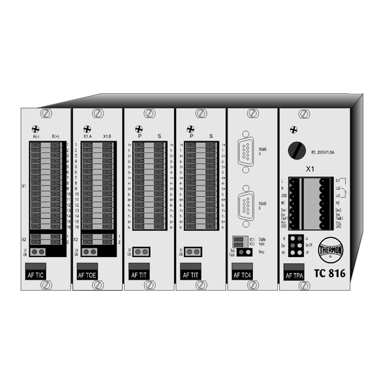
TC 816 Operation Manual The TC 816 for Process Temperature Maintenance The enclosure of the TC 816 is constructed to be mounted on the back plane of a panel. The enclosure facili- tates 6 slots for electronic modules, each having its particular task. -
Page 6: Slot 3: For Af Tit Tracing Input Module For Temperature
The advantage is, that off the shelf Solid State relays can be connected to the TC 816 so switching capacity of a TC 816 system is only limited by the panel construction parameters like feeding power, cooling capacity in the panel. -
Page 7: The Tcd 01 Tracing Control Display
The TCD 01 tracing control display allows the operator to have full control over the heat tracing circuits which are controlled by the connected TC 816 temperature controllers. The TCD 01 is the host on the RS 485 data communication bus. It searches on the communication bus for TC 816 heat tracing temperature controllers which need to have their own unique communication address (to be set by DIP switches on the AF TC4 tracing central processing module). -
Page 8: Description Of The Tcd 01
TCD 01 System Alarm Light Illuminates when the hardware controlled self check detects a program stop in the TCD 01 tracing control display ® THERMON…The Heat Tracing Specialists Page 8 of 42 Operation Manual 0503 E TC 816... -
Page 9: Start - Up Of The Tcd 01
• having setup the hardware wiring of the RS 485 data communication bus • setting the communication address of the connected TC 816 controllers • and applying the 24 Vdc power supply The TCD 01 tracing control display illuminates yellow and looks as below: Figure 4.2... -
Page 10: Configuration Of The Tcd 01 In General Settings (Setup) Menu
SELECTION you can select the appropriate parameter to be changed. By pressing the buttons below SETPOINT you can change the values of the parameters. ® THERMON…The Heat Tracing Specialists Page 10 of 42 Operation Manual 0503 E TC 816... -
Page 11: Number Of First Circuit
: means no password protection of parameters NOTE: The password must always be set in case a TC 816 configured as Heat Tracing Cable Temperature Limiter is connected to the TCD 01. It ensures that all trips of that safety device can only be acknowl-... -
Page 12: Password Input
The password value is entered with the ENTER button . If the password is correct the TCD 01 continues to the desired Parameter display or to the General Settings Menu. ® THERMON…The Heat Tracing Specialists Page 12 of 42 Operation Manual 0503 E TC 816... -
Page 13: Data Communication Bus Search
Data Communication Bus Search After the Start-Up screen is left automatically or the General Settings Menu has been left by pushing the ac- knowledge button, the TCD 01 starts searching the RS 485 communication bus for connected TC 816 heat tracing temperature controllers. - Page 14 TCD 01 with the original circuit numbers. After choosing CONFIRM SKIP the TCD 01 automatically switches to heat tracing circuit display. ® THERMON…The Heat Tracing Specialists Page 14 of 42 Operation Manual 0503 E TC 816...
-
Page 15: Heat Tracing Circuit Display
TCD 01 Tracing Control Display: Heat Tracing Circuit Display for three phase current display By pressing the buttons below CIRCUIT you can scroll through the heat tracing circuits. ® THERMON…The Heat Tracing Specialists Operation Manual 0503 E TC 816 Page 15 of 42... -
Page 16: Heat Tracing Circuit Numbers And Tc 816 Zone Numbers
-line) , using: Zone 17 of TC 816 controller with communication address 1. The TC 816 automatically assigns Zone 17 to Zone 1 of the same controller if at start-up an AF TIC Tracing Input module for load Current is detected. -
Page 17: Controller And Zone Assignment [C01Z01]
• the assigned TC 816 communication address • the assigned controller Zone number of the applicable TC 816 controller. With CURRENT LIMITER values and values some analogue inputs are linked together as one circuit,... -
Page 18: Column: Alarm
RS 485 data communication bus. -OFF- Alarm condition monitoring disabled This situation occurs if the heat tracing circuit is set to manual or OFF (parameter P06) ® THERMON…The Heat Tracing Specialists Page 18 of 42 Operation Manual 0503 E TC 816... - Page 19 RS 485 data communication bus. -OFF- Alarm condition monitoring disabled This situation occurs if the heat tracing circuit is set to manual or OFF (parameter P06) ® THERMON…The Heat Tracing Specialists Operation Manual 0503 E TC 816 Page 19 of 42...
-
Page 20: Acknowledge Controller And Current Alarms
TCD 01 for three phase current display per tracing circuit, with firmware AZ 884, will not sound an audi- ble alarm. Also the applicable hardware alarm contacts of the AF TPA Thermon Power supply module AC trip (see TC 816 Hardware Configuration Guide). -
Page 21: Acknowledge Heat Tracing Cable Temperature Limiter Trips
TCD 01 for three phase current display per tracing circuit, with firmware AZ 884, will not sound an audi- ble alarm. Also the hardware high alarm contacts of the AF TPA Thermon Power supply module AC will trip (see TC 816 Hardware Configuration Guide). - Page 22 NOTE: Heat Tracing Cable Temperature Limiter will NOT switch the heat tracing back on unless the trip has been acknowledged the alarm status has disappeared. ® THERMON…The Heat Tracing Specialists Page 22 of 42 Operation Manual 0503 E TC 816...
-
Page 23: Changing Set Points
7. The brackets around the set point will disappear automatically after about half a minute, if no buttons have been pressed. NOTE: Zones are not supervised when their set point is set to 0. ® THERMON…The Heat Tracing Specialists Operation Manual 0503 E TC 816 Page 23 of 42... -
Page 24: Changing Parameter Values
7. By pressing the buttons below you can select the appropriate parameter to be changed. Notice the change of parameter description in the top line. ® THERMON…The Heat Tracing Specialists Page 24 of 42 Operation Manual 0503 E TC 816... - Page 25 Those parameters can only be changed with the Paracon or Visual Fecon software through a PC connected to one of the data communication busses. ® THERMON…The Heat Tracing Specialists Operation Manual 0503 E TC 816 Page 25 of 42...
-
Page 26: Parameters
(heat tracing design) engineer. Changing Parameters P16 through P29 is possible by: 1. Set DIP 2 of 5 pole DIP switch of AF TC1/4/5 to ON-position (see TC 816 Hardware Configuration Guide). 2. Use one of the following tools to alter Parameters P16 through P29: - TCD 01 (single phase current display) with firmware AZ871 rev.2.41 or higher... -
Page 27: Parameter P02: Hi-Alarm
Measurement above the value set for parameter P02 triggers the respective zone HI-ALARM , this results • tripping the appropriate Hi-alarm contact on the AF TPA Thermon Power supply module AC • the green Hi-LED on the AF TPA module extinguishes Adjustment thresholds: 0...630... -
Page 28: Parameter P04: Al Delay
This function is useful in order to avoid alarm trips in case for instance the equipment, traced with a suitable high temperature heating cable is steamed out. Adjustment thresholds: 0...999 Default value: ® THERMON…The Heat Tracing Specialists Page 28 of 42 Operation Manual 0503 E TC 816... -
Page 29: Parameter P05: Digi In
The right panel door can be addressed immediately by checking the circuit number in the panel drawings. In case the TC 816 controller is not configured for load current monitoring with an AF TIC Tracing Input mod- ule for load Current, the MCB/RCD status monitoring allows you to distinguish between: •... -
Page 30: Parameter P06: Op Mode
- Zones 1 through 16 - unit in: not applicable • Valid for Limiter Zones - Zones 1 through 16, possibly of different TC 816 unit on same data communication bus - unit in: not applicable • Valid for Current Zones... -
Page 31: Parameter P07: Man Outp
P07 determines the power output in % in case Parameter P06: MODE is set to “1” (manual operation). See chapter 4.2.6. The TC 816 regulates power output by switching ON and OFF (cycling) the supply voltage within a certain cycle time (parameter P25 CYCL TIME... -
Page 32: Parameter P08: Max Outp
- unit in: 0,1 x A => value of 10 means 1 A OFFSET Parameter P10 allows field tuning of temperature and current by adjusting the Range: -50...+50 Default value: ® THERMON…The Heat Tracing Specialists Page 32 of 42 Operation Manual 0503 E TC 816... -
Page 33: Parameter P11: Coil Fact
- unit in: s (seconds) • Not valid for Limiter Zones • Not valid for Current Zones In case the TC 816 is configured for: • Frost Protection with Staged Start-Up control concept (default parameter P12 setting) • Parameter P18 (... -
Page 34: Parameter P13: Spare
4.2.13 Parameter P13: Spare This Parameter has no function, it is a spare parameter to give the possibility of future functional expansion of the TC 816 heat tracing temperature controller. 4.2.14 Parameter P14: Spare This Parameter has no function, it is a spare parameter to give the possibility of future functional expansion of the TC 816 heat tracing temperature controller. -
Page 35: Zone Parameters Configured By Heat Tracing Supplier
EN 50 014 standard for electrical equipment in hazardous area the limiter Zone needs to be utilised by a separate electronic controller. Within the TC 816 multi circuit temperature controller concept that can be any other TC 816 controller set up as a heat tracing cable temperature limiter (see chapter 1.1.3). -
Page 36: Parameter P18: Ctr Mode
Not valid for Limiter Zones • Not valid for Current Zones CTR MODE Parameter P18 determines the TC 816 control mode ( ). Possible control modes are: • PID control: The temperature controller Zone controls according to PID (Proportional Integral &... -
Page 37: Parameter P19: P Heat
P HEAT With parameter P19 the proportional band ( ) of the controlled heat tracing circuit is set in % (per- centage). The resulting proportional band derives from the TC 816 globally set maximum temperature value (default 700 °C). P HEAT If, for example, is set to 10 % and the maximum temperature value is 700 °C, the effective pro-... -
Page 38: Parameter P21: D Heat
Default value: 4.3.8 Parameter P23: Spare This Parameter has no function, it is a spare parameter to give the possibility of future functional expansion of the TC 816 heat tracing temperature controller. ® THERMON…The Heat Tracing Specialists Page 38 of 42... -
Page 39: Parameter P24: Hyster
Not valid for Current Zones Control mode set to ON/OFF control, see chapter 4.3.3. HYSTER Parameter P24 determines the hysteresis ( ) of the ON/OFF control actions of the TC 816 heat tracing temperature controller. Adjustment thresholds: 1...30 Default value: 4.3.10 Parameter P25: CYCL TIME... -
Page 40: Parameter P26: Sensor
Adjustment thresholds: 1...16 (only if P28 is set to default) Default value: own Zone number MS MODE Note: This Parameter has no effect if P28 is not in default position. ® THERMON…The Heat Tracing Specialists Page 40 of 42 Operation Manual 0503 E TC 816... -
Page 41: Parameter P27: Outp
Note: Never adjust this parameter for Zones 1 through 16 other than default (own Zone number) if Parame- SENSOR # ter P26 ( ) is not in default position. ® THERMON…The Heat Tracing Specialists Operation Manual 0503 E TC 816 Page 41 of 42... -
Page 42: Parameter P28: Ms Mode
In the most extreme case the actual circuit can be controlled by 16 temperature sensors. Parameter P28 determines the TC 816 Multi Sensor mode ( MS MODE ). Possible multi sensor modes are: •...
Need help?
Do you have a question about the TC 816 and is the answer not in the manual?
Questions and answers