Table of Contents
Advertisement
Quick Links
6 TECHNICAL
6.2 EASERA GATEWAY SPECIFICATIONS
Preamp Bandwidth
Preamp Input Impedance
Instrument Input Impedance
Preamp THD
Preamp EIN
Preamp Gain
Line Input Impedance
TRS Output Impedance
TRS Main Outputs Impedance
Headphone Output
Phantom Power
Power Supply
Bus Power
Analog to Digital Converters
ADC Dynamic Range
DAC
DAC Dynamic Range
IEEE1394 Speed
As a commitment to constant improvement, PreSonus Audio Electronics, Inc. reserves the
right to change any specification stated herein at any time in the future without notification.
DISTRIBUTED BY
Renkus-Heinz, Inc., 19201 Cook Street, Foothill Ranch, CA 92610-3501, USA
Tel: 949-588-9997
Fax: 949-588-9514
Web: www.renkus-heinz.com
10Hz to 50kHz
1.3k Ohms
1M Ohms
<0.005%
-125dB
45dB
10k Ohms
51 Ohms
51 Ohms
150mW/Ch 20Hz-20kHz
48V +/- 2V
Ext line Transformer, Internal
Switching
Six-pin FireWire Port
24-bit / up to 96khz
107db
24-bit / up to 96kHz
110db
400mbps
:
Email: Sales@renkus-heinz.com
RH583 9/06
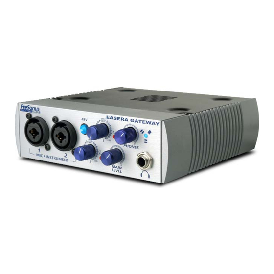
EASERA Gateway
Data Acquisition System
Users Manual
Version 1.0
PreSonus Audio Electronics, Inc.,
©
2005
Advertisement
Table of Contents

Summary of Contents for PRESONUS EASERA
-
Page 1: Users Manual
6 TECHNICAL EASERA Gateway 6.2 EASERA GATEWAY SPECIFICATIONS Data Acquisition System Preamp Bandwidth 10Hz to 50kHz Preamp Input Impedance 1.3k Ohms Instrument Input Impedance 1M Ohms Preamp THD <0.005% Preamp EIN -125dB Preamp Gain 45dB Line Input Impedance 10k Ohms... - Page 2 All authorized returns Q: I just bought a EASERA GATEWAY from (dealer name goes here) in (city and state go must be sent to the PreSonus repair facility postage prepaid, insured and properly pack- here) and I live in Morocco.
-
Page 3: Table Of Contents
2 Installation and Set up EASERA GATEWAY’s hardware control panel. 2.1 Computer Requirements 2.2 Installation of EASERA GATEWAY Drivers No Sync (Red) – Macintosh Users – Open Audio MIDI Setup and change the 2.3 EASERA GATEWAY Control Panel Format sample rate speed to anything different. This will re-establish synchronization 2.4 EASERA GATEWAY Mixer... -
Page 4: Overview
Central Time. Pops and Clicks The light on the front right panel of the EASERA GATEWAY is a clock (sync) indicator. It lets you know if your unit is receiving word clock correctly. Word clock is the manner by which digital devices sync frame rates. Proper word clock sync prevents digital devices from having pops, clicks, or distortion in the audio signal (due to mismatched digital audio transmission). -
Page 5: Installation And Setup
MIXER 2 INSTALLATION AND SETUP 2.1 COMPUTER REQUIREMENTS Below are the minimum computer system requirements for your EASERA GATEWAY. OUTPUT SECTION Windows Output Level (fader) – Adjusts the output level of the mixer. - OS: Microsoft Windows XP - Computer: Windows compatible computer with FireWire port. -
Page 6: Installation Of Easera Gateway Drivers
(balance between left and right chan- nels), LEVEL, SOLO and MUTE. This is (NOTE: If you are connecting the EASERA GATEWAY via a standard 6-pin Firewire cable, a stereo channel. This channel picks up power for the unit will be supplied via the Firewire cable. If you are using a 4 to 6-pin... -
Page 7: Easera Gateway Control Panel
4 MIXER 2 INSTALLATION AND SETUP 6. In the MIXER OUTPUT section of the EASERA GATEWAY Mixer, select the pair of out- puts to send out of the EASERA GATEWAY (for example studio monitors connected to out- puts 1/2). 4.2 OPERATION OF MIXER The silver tracks represent the six possible inputs from the EASERA GATEWAY as well as the software playback. - Page 8 3.Connect your microphone to input 1 and turn on phantom power if needed. Note that when the Gateway is used with EASERA, the sample rate can also be set direct- ly in EASERA. 4.You can now adjust the levels of your microphone and your software playback to your desired levels for recording (monitoring only).
- Page 9 – called latency. Therefore, you can mix the input signal going into the EASERA GATEWAY with the playback from your soft- Latency: – Sets the amount of delay time of your EASERA GATEWAY (1.5ms – 24ms).
- Page 10 Input Level Boost: clicking this button will boost the input level of each corresponding DB9 Connector Breakout Cable analog input on the EASERA GATEWAY by +12dB. Use this feature for recording quiet instruments or devices with low output. Line Outputs (3, 4, 5, 6). Balanced line level outputs. These connectors will accept either balanced (TRS –...
-
Page 11: Easera Gateway Mixer
EASERA GATEWAY from the FireWire connector. If your computer has a 4 pin connector, then you will need to get a 4 to 6 pin connector to connect your EASERA GATEWAY to your computer, and use the external power supply. Either port can be used to connect the EASERA GATEWAY to a FireWire port on your computer. -
Page 12: Front Panel Layout And Descriptions 12
4. Main Level. This knob allows control over the output level for the MAIN CR OUTPUT 1 and 2 on the back of the EASERA GATEWAY. It has a range of -80db to +10dB. 5. Headphone Symbol and ¼” Jack. This is where you connect your headphones.
Need help?
Do you have a question about the EASERA and is the answer not in the manual?
Questions and answers