Table of Contents
Advertisement
Quick Links
Advertisement
Table of Contents

Related Manuals for Inter-m ECS-9216


Summary of Contents for Inter-m ECS-9216
- Page 1 Operation Manual Emergency Combination System ECS-9216...
-
Page 2: Table Of Contents
EMERGENCY COMBINATION SYSTEM Contents Contents Welcome Warning............................1 Unpacking ............................2 Installation Environment............................2 Important Safety Instructions......................2 Features ............................3 Operation ............................3 Front Panel ............................4 Rear Panel ............................5 Installation ............................7 Applications ............................9 Block Diagram ..........................11 Specifications ..........................12 Service Procedures............................13 Schematic .............................13 Parts List ............................13 Variations and Options .......................13 Warranty... -
Page 3: Warning
A personal welcome to you from the management and employees of Inter-M All of the co-workers here at Inter-M are dedicated to providing excellent products with inherently good value, and we are delighted you have purchased one of our products. -
Page 4: Unpacking
S3125A S3125A ECS-9216... -
Page 5: Features
- 2 AND 3 WIRE SPEAKER LINE SYSTEM You can control the speaker line on the 2 wire system or 3 wire system. - EXTENSION FUNCTION You can easily expand by connecting additional ECS-9216. Operation Operation 1. Supply the power. -
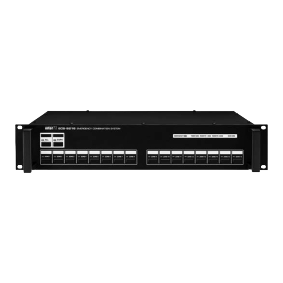
Page 6: Front Panel
These leds display the priority status. The priority is Emergency > Timer > Remote1 > Remote2 > Main(BGM). 4. SPEAKER CHANNEL SELECT SWITCHS AND SPEAKER CHANNEL LEDS These switch select individual channel 1 through 16. On the Emergency mode, the speaker channel leds are red. On the Normal mode, the speaker channel leds are green. ECS-9216... -
Page 7: Rear Panel
This terminal is for input of the Inter-M Timer(ex: PW-9242N). This is connected to the timer switch of Inter-M Timer. All speaker channels will be selected when the timer switch is on. 8. LINK IN CONNECTOR This connector is for extension of additional ECS-9216. This is connected to the link out of an additional ECS-9216. ECS-9216... - Page 8 EMERGENCY COMBINATION SYSTEM 9. LINK OUT CONNECTOR This connector is for extension of additional ECS-9216. This is connected to the link in of an additional ECS-9216. 10. DC INPUT/OUTPUT CONNECTOR This connector is the DC power input and output connector. The DC input is for the connection of 24VDC power supply.
-
Page 9: Installation
* CAUTION A PD-9359 is able to supply DC 120W so, please set the total DC power of devices (Ref: ECS-9216 is 14W, EP-916 is 4W, RM-916 is 6W) under maximum power supply by PD-9359. 1. Turn off the power before installation of the system. Installing on the power-on may make a trouble. - Page 10 (Figure 4) Connect the fire sensor signal of fire panel to the fire sensor input of ECS-9216 like Figure 4. The fire alarm will be given to the speaker channel 1~4 by fire sensor signal 1, and the speaker channel 2~6 by fire sensor signal 2.
-
Page 11: Applications
EMERGENCY COMBINATION SYSTEM Applications Applications ECS-9216... - Page 12 EMERGENCY COMBINATION SYSTEM AC IN ECS-9216...
-
Page 13: Block Diagram
EMERGENCY COMBINATION SYSTEM Block Diagram Block Diagram ECS-9216... -
Page 14: Specifications
EMERGENCY COMBINATION SYSTEM Specifications Specifications ECS-9216 Priority Control Emergency > Timer > Remote1 > Remote2 > Main Link in/out Interface RS-422(19200bps, Data 8bits, Stop 1bit, Non Parity bit, Start 1bit) Link in/out Interface Distance 1.2km Operating Temperature 0°C ~ +40°C... -
Page 15: Service
To obtain specific warranty information and available service locations contact Inter-M directly or the authorized Inter-M Distributor for your specific country or region. - Page 16 Inter-M, Ltd. (Korea) began operations in 1983. Since then, Inter-M has grown to become one of the largest manufacturers of professional audio and commercial sound electronics equipment in the world. Inter-M has gained worldwide recognition for its own branded products, as well as private label manufacturing of electronics sold under other names (OEM).
Need help?
Do you have a question about the ECS-9216 and is the answer not in the manual?
Questions and answers