Table of Contents
Advertisement
Advertisement
Table of Contents
Troubleshooting

Subscribe to Our Youtube Channel
Related Manuals for Echelon SLTA-10


Summary of Contents for Echelon SLTA-10
- Page 1 SLTA-10 Adapter User’s Guide Revision 1 ® C o r p o r a t i o n 078-0160-01B...
- Page 2 Parts manufactured by vendors other than Echelon and referenced in this document have been described for illustrative purposes only and may not have been tested by Echelon. It is the responsibility of the customer to determine the suitability of these parts for each application.
- Page 3 Preface ® This document describes how to use the SLTA-10 Serial LonTalk Adapter to connect a host processor, with an EIA-232 (formerly RS-232) serial interface, ® to a L network. ORKS SLTA-10 Adapter User’s Guide...
-
Page 4: Content
Chapter 10 describes initilization and installing as a node. • Chapter 11 discusses using an SLTA-10 Adapter with a modem. • Chapter 12 describes the DOS Host Connect Utility (HCU) for use with the SLTA-10 MIP mode. • Chapter 13 is a troubleshooting section. -
Page 5: Related Manuals
• The LC Object and Data Server Programmer’s Guide describes how to write a 32-bit Windows host application and installation tool that can be used with the SLTA-10 NSI mode. • The L Host Application Programmer’s Guide describes how to write a host ORKS application that can be used with the SLTA-10 MIP mode. - Page 6 SLTA-10 Adapter User’s Guide...
-
Page 7: Table Of Contents
Content Related Manuals Web Access SLTA-10 Adapter Overview Introduction Two Modes of Operation: SLTA-10 NSI and MIP Modes SLTA-10 NSI Mode Features SLTA-10 MIP Mode Versus the SLTA/2 The SLTA-10 Adapter Configurations Software Availability LNS 1.0, 1.01, and 1.5 Compatibility... - Page 8 Installing the SLTA-10 MIP Mode Adapter Software Installing the Windows 3.1x DLL Software Other Drivers Using the Windows NT Driver and SLTALink Manager with SLTA-10 NSI Mode Software Overview Establishing a Communications Line for Dialing in to a Network Establishing a Communication Line for Calls Dialed out to the PC...
- Page 9 Installing an SLTA-10 Adapter on a Network Installing with LNS Installing with the LonBuilder or NodeBuilder Tools Installing an SLTA-10 Adapter with LonManager API, the DOS-based LonMamager LonMaker Installation Tool, or DDE Server 11 Using the SLTA-10 Adapter with a Modem...
- Page 10 Install NVConnect (NSI mode only) Install NSIConnect (NSI mode only) Install CallbackEnable (NSI mode only) Report SLTAEE (NSI mode only) Modem Compatibility 12 Using the DOS Host Connect Utility with the SLTA-10 MIP Mode HCU Usage Theory of Operation Usage Examples Suggested Modem Configurations...
-
Page 11: Slta-10 Adapter Overview
PCs, workstations, embedded microprocessors, and microcontrollers. The SLTA-10 Adapter has two modes of operation: NSI and MIP modes. The SLTA-10 NSI mode is compatible with LNS-based applications. The SLTA-10 MIP mode is compatible with legacy applications based on ®... -
Page 12: Introduction
The SLTA-10 Adapter can be set up to answer incoming calls from a remote host. In addition, any node on the local network can initiate a telephone call to a remote host computer. A new feature, available only in the SLTA-10 NSI mode (see below), allows the SLTA-10 Adapter itself to initiate a phone call to a remote host computer. -
Page 13: Two Modes Of Operation: Slta-10 Nsi And Mip Modes
LNS-compliant applications, and network interface functionality (MIP mode) for use with LonManager API-based applications. There are two separate firmware images in the SLTA-10 Adapter. The two separate images have different link layer protocols, different network drivers, different buffer capacity, and different functionality. -
Page 14: Slta-10 Nsi Mode Features
SLTA-10 NSI Mode Features The most important new feature of the SLTA-10 NSI mode is the NSI functionality for use with LNS-compliant applications. Other important features available only in the SLTA-10 NSI mode include: SLTA-10 initiated dial-out, a Windows NT driver, a high performance link layer protocol, and the SLTALink Manager software. -
Page 15: Lns 1.0, 1.01, And 1.5 Compatibility
Adapter may be used without issue with applications based on LNS 1.0, 1.01, or 1.50. The SLTA-10 Adapter is also designed so that a PC host can be connected to the network through a pair of modems and the telephone network. In this scenario, the PC is a remote host. When the PC initiates the phone call to the SLTA-10 Adapter, the remote host is said to “dial-in to the... -
Page 16: Tapi Compatibility
The SLTALink Manager software uses TAPI release 1.3 or higher. This is supported in Windows NT 4.0, but not in Windows NT 3.51. Thus, Windows NT 3.51 does not support the use of the SLTA-10 Adapter with modems, however, Windows NT 3.51 does support a direct connect interface. -
Page 17: Slta-10 Adapter Hardware
Chapter 2 SLTA-10 Adapter Hardware This chapter provides a physical description of the SLTA-10 Adapter. SLTA-10 Adapter User’s Guide... -
Page 18: Mechanical Description
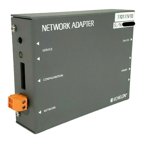
Mechanical Description Figures 2 and 3 show the SLTA-10 Adapter in its enclosure. Figure 4 shows the SLTA-10 Adapter board without an enclosure. Figure 2 SLTA-10 Adapter Enclosure SLTA-10 Adapter User’s Guide... - Page 19 Figure 3 shows a 1:1 view of the enclosure and may be used as a mounting template. Figure 3 SLTA-10 Adapter Enclosure Keyhole View Mounting Slots SLTA-10 Adapter User’s Guide...
-
Page 20: Switches, Indicators, And Connectors
Power Input Connector SLTA-1Ø © ECHELON 1996 Figure 4 SLTA-10 Adapter Without Enclosure (Component-Side View from Top). Switches, Indicators, and Connectors ESD Warning This product contains components which are sensitive to static electricity. Before installing or removing the network or serial cables, touch earth ground with your hand to discharge any static electricity which may have accumulated. - Page 21 Table 2 describes the external connections and switches/LEDs on the SLTA-10 Adapter. Table 2 SLTA-10 Adapter Interfaces Interface Function Service Button S2 Pressing this switch grounds the service request pin on the Neuron Chip within the SLTA-10 Adapter. While this switch is pressed, the service LED should light to maximum intensity.
-
Page 22: Connecting Power
Once the SLTA-10 Adapter is physically attached to the desired channel, power must be supplied via one of the power input connectors. The SLTA-10 Adapter may be ordered with a plug-in power supply, or may be used with any 9 - 30VAC/DC supply. Four plug-in power supply options are available for the SLTA-10 Adapter, depending on the country in which the SLTA-10 Adapter is used: USA/Canada, United Kingdom, Continental Europe, or Japan. - Page 23 When power is connected, the yellow service LED will briefly flash and the green power indicator LED will turn on. Once an SLTA-10 Adapter is powered and configured, the service LED will remain off unless the service request switch is pressed.
- Page 24 SLTA-10 Adapter User’s Guide...
-
Page 25: Cabling And Connections
Chapter 3 Cabling and Connections This chapter demonstrates how to attach the SLTA-10 Adapter to a L ORKS network, a PC, and a modem. SLTA-10 Adapter User’s Guide... -
Page 26: Attaching The Slta-10 Adapter
SLTA-10 Adapter to a PC, simply connect one end of the serial cable to the SLTA-10 Adapter, and the other end of the cable to the PC’s serial port. To connect an SLTA-10 Adapter to a modem, a special null modem cable must be used. Note that a standard off-the-shelf null modem cable will not work in this configuration. -
Page 27: Attaching The Slta-10 Adapter To A Modem
Figure 6 PC 25-Pin to DB-9 Connection Attaching the SLTA-10 Adapter to a Modem You must use the specific null modem cable described below to attach the SLTA-10 Adapter to a modem. Table 7 DCE Modem to SLTA-10 Adapter Connection (DB-9 to DB-9) -
Page 28: Attaching The Slta-10 Adapter To A Network
Figure 8 SLTA-10 Adapter Null Modem Cable (DB-25 to DB-9) Attaching the SLTA-10 Adapter to a Network The network connector for the SLTA-10 Adapter is an orange two-conductor block type. Use the 2- pin conductor that comes with the SLTA-10 Adapter to connect to the twisted-pair network. -
Page 29: Hardware Configuration
Chapter 4 Hardware Configuration This chapter describes how to install and configure an SLTA-10 Adapter. SLTA-10 Adapter User’s Guide... -
Page 30: Configuring The Slta-10 Adapter Hardware
There are eight configuration switches on the SLTA-10 Adapter's switch block (S1). These inputs are read by the SLTA-10 firmware to configure or enable features. Figure 10 shows the factory default settings for the SLTA-10 Adapter. Changes to the switch configurations will not occur until the power is cycled on the SLTA-10 Adapter. -
Page 31: Modem Support (Switch2 / Cfg2)
. ALERT/ACK link protocol (down position) is the default setting for the SLTA-10 Adapter. When the SLTA-10 Adapter uses the ALERT/ACK protocol and it wishes to send data to the host, it first sends a single ALERT character (hex 01). The host then responds with an ALERT ACK character (hex FE) to indicate its readiness to accept the rest of the data. -
Page 32: Network Disable (Switch3 / Cfg1)
Switch 3 / CFG1 enables (down position) or disables (up position) network communications after reset. If disabled, the SLTA-10 Adapter will not be able to communicate on the network after a reset until it receives an niFLUSH_CANCEL command from the host. -
Page 33: Serial Network Services Interface (Switch4 / Nsi)
Figure 14 SLTA-10 Adapter Firmware Switch 4 / NSI The SLTA-10 Adapter has an SLTA-10 NSI-mode firmware switch which is Switch4 / NSI. It is factory set in the up position for use of the SLTA-10 NSI mode firmware. The down position is for the MIP mode firmware. -
Page 34: Autobaud (Ab)
Autobaud must not be used when the SLTA-10 Adapter is used with a modem. When autobaud is enabled, the SLTA-10 Adapter matches the serial bit rate of a local host. When powered, the SLTA-10 Adapter looks for a ‘0’ byte from the host. The SLTA-10 Adapter cycles through all the serial bit rates until a ‘0’... - Page 35 38,4 00 bps 1 200 bps 19,2 00 bps 300 bps Figure 16 SLTA-10 Adapter Serial Baud Rate Switches 6, 7, and 8 / BAUD[2..0] Table 10 SLTA-10 Adapter Autobaud Switch Configuration Autobaud BAUD Switches ‘ /A ’ Option on ‘...
-
Page 36: Configuring The Slta-10 Adapter Software
SLTA-10 Adapter. The tables also list the maximum size of the buffer memory pool. If the SLTA-10 Adapter is configured to use more bytes than are available in the pool, it will behave erratically since the RAM is used by the SLTA-10 firmware. - Page 37 The NODEUTIL node utility application, available on Echelon’s web site, can be used to modify the MIP mode buffer configuration from a PC host. See the README.TXT file included with NODEUTIL for details. By default, the SLTA-10 NSI-mode program ID consists of 8 bytes of program identification information (80-00-01-01-03-00-xx-3C, where ‘xx’...
- Page 38 SLTA-10 Adapter User’s Guide...
-
Page 39: The Slta-10 Nsi Mode Software
Starter Kit (Model 58030-01) as part of the LNS Developer’s Kit for Windows (Model 34303), versions 1.5 and higher, and on the Echelon web site at www.echelon.com. Skip this Chapter if you are using the SLTA-10 MIP mode. SLTA-10 Adapter User’s Guide... -
Page 40: Slta-10 Nsi Mode Software Overview
SLTA-10 Adapter is loaded in ROM and cannot be reprogrammed. Using the SLTA-10 NSI mode, the host application may be one of two types. The first type of host application is an LNS-based application, developed with the LNS Developer’s Kit for Windows. -
Page 41: Windows Nt Software Installation Results
Windows NT Software Installation Results The Windows NT installation software loads a selection of new files and updated Echelon files to different locations on the PC's hard drive. The function and location of these files can be found in readme.txt . - Page 42 SLTA-10 Adapter User’s Guide...
-
Page 43: The Slta-10 Mip Mode Software
This software is basically an updated version of the SLTA/2 adapter software. There is no 32-bit Windows driver available for the SLTA-10 MIP mode. Skip this Chapter if you are using the SLTA-10 NSI mode. SLTA-10 Adapter User’s Guide... -
Page 44: Slta-10 Mip Mode Software Overview
SLTA-10 Adapter connection when the SLTA-10 Adapter is used with a remote host. An example written in Neuron C is also provided as a basis for user-developed nodes on a L... - Page 45 PCs running DOS (see also the UNIX network driver sources). See Chapter 8 for a description of the SLTA-10 Adapter DOS network driver and Chapter 9 for a description of how to write an SLTA-10 Adapter network driver for other hosts. See Chapter 4...
- Page 46 A description of the sample host application. README.TXT An executable version of the sample host application for HA.EXE DOS. The SLTA-10 Adapter DOS network driver must be installed to run this application. The main program for the example. HA.C A general purpose network interface library that can be NI_MSG.C...
-
Page 47: Installing The Windows 3.1X Dll Software
Neuron C Connection Example. A sample Neuron C program is contained in the NC_APPS directory. This program shows how a node on a network connected to the SLTA-10 Adapter can dial out and connect to a remote host computer. The files supplied are: Neuron C source program to dial out with the SLTA-10 DIALOUT.NC... -
Page 48: Other Drivers
See Appendix A for information on using the Windows DLL. Other Drivers A UNIX network driver and source code for the SLTA-10 MIP mode is available on the Echelon web site (http://www.echelon.com). Chapter 9 discusses creating a SLTA-10 MIP mode driver for any host. -
Page 49: Using The Windows Nt Driver And Sltalink Manager With Slta-10 Nsi Mode
This chapter describes the SLTALink Manager software, which establishes and configures local and remote links from the host PC to the SLTA-10 Adapter in NSI mode. A remote link requires a pair of modems: one attached to the SLTA-10 Adapter and the other attached to the host PC. -
Page 50: Software Overview
Finally, the SLTALink Manager includes many diagnostic functions. The SLTA-10 Adapter Link Manager software is used to control a remote SLTA-10 via a set (2) of modems by using the Telephony Application Programming Interface (TAPI) services which are built into the Windows NT 4.0+ operating system. -
Page 51: Establishing A Communications Line For Dialing In To A Network
Dialing Preferences is chosen from the Line menu. This message will only appear when telephony information has not been provided. This case usually occurs if the computer has never been configured to use a modem. e Message SLTA-10 Adapter User’s Guide... - Page 52 — as shown in figure 20 as “Dialing from: The Office” — the Windows Dialing Properties window (figure 22) will be displayed instead. The Dialing Properties window is a tabbed subset of the Windows Telephony Control Panel. Figure 21 Windows Location Information Window SLTA-10 Adapter User’s Guide...
-
Page 53: Establishing A Communication Line For Calls Dialed Out To The Pc
Line window that is displayed when “Monitor for SLTA dial-in” is chosen from the Line menu. Only one line or modem can be monitored at a given time by the SLTALink Manager software. However, multiple modems may be used for dialing into a network concurrent with monitoring the one modem. SLTA-10 Adapter User’s Guide... -
Page 54: Establishing Remote And Local Network Sites
Choosing Select/Action from the Link menu will display a screen similar to the screen shown in figure 24. Figure 25 shows the default local setup. Figure 24 Completed SLTALink Selection Window Figure 25 Default SLTALink Selection SLTA-10 Adapter User’s Guide... -
Page 55: Name Of Link
Link Type The type of link specifies whether the SLTA-10 is directly connected to the PC (Local), or if the SLTA-10 is at a different location and must be accessed via a set of modems (Remote). Configuring the Modem Line Clicking on “Configure Line”... -
Page 56: Slta Password
SLTA Password The Password box allows the user to enter the password for a remote SLTA-10 Adapter. Up to eight characters may be entered. If entered, the password will be sent to the remote SLTA-10 adapter when a connection is made. -
Page 57: Diagnostics
SLTA-10 Adapter. The Service button will cause the SLTA-10 Adapter to broadcast a service pin message on the network. The reset button causes a reset of the Neuron Chip in the SLTA-10 Adapter, but does not clear the Neuron Chip’s system image. -
Page 58: Using The Dos "Stub" Driver
The DOS stub driver, which is added as part of the install, allows DOS and Windows 3.1x applications to run on top of the SLTA-10 driver for Windows NT. The following line is required in the CONFIG.NT file that is loaded on startup: DEVICE=%SystemRoot%\system32\PCLTDOS.SYS /D n... -
Page 59: Dial-Out To The Remote Pc Only
– with the correct database and device driver name. One system solution is to create a separate link for each SLTA-10 Adapter. Each link then stores the Remote Identifier of its SLTA-10 Adapter after the first connection. Upon connection, the appropriate application and command line arguments stored in the link get launched. -
Page 60: Callback
The SLTA-10 Adapter callback functionality works as follows: A call is initiated from some remote PC to an SLTA-10 Adapter on a network, which must have its NSI mode EEPROM configured to require callback. See Chapter 11 for more information on configuring the SLTA-10’s EEPROM. -
Page 61: Monitoring: Application Termination Strategy
Monitoring: Missing Messages after a Dial-Out In general, the message that triggers a dial-out from the SLTA-10 on the network to a remote PC host is lost. When a network variable update is sent to the SLTA-10 Adapter and no phone connection is currently up and running, the SLTA-10 Adapter is typically configured to dial-out to the host. -
Page 62: Monitoring: Lns Application Design Issues
Use these guidelines to avoid the system-level failures detailed above: When expecting the SLTA-10 Adapter to dial-out from the network to a remote PC, dedicate one SLTA-10 Adapter to dial-out and always have that SLTA-10 Adapter connect to the same remote PC. - Page 63 Several PCs can share one SLTA-10 Adapter as long as the calls are all initiated on the remote PC hosts (i.e., dial-in only) and each remote LNS application removes the bound connections to its host before terminating. See figure 29.
- Page 64 Network Driver M o d e m Dial-in and Dial-out to the LNS Server M o d e m Null Modem Cable SLTA-10 Adapter Transceiver Interface LonWorks Devices Figure 28 Dedicated SLTA-10 Adapter hosting the NSS SLTA-10 Adapter User’s Guide...
- Page 65 Network Driver M o d e m M o d e m Dial-in M o d e m Null Modem Cable SLTA-10 Adapter Transceiver Interface LNS Server LonWorks Devices Figure 29 Shared SLTA-10 Adapter using Dial-in SLTA-10 Adapter User’s Guide...
- Page 66 SLTA-10 Adapter User’s Guide...
-
Page 67: Using The Dos Driver With Slta-10 Mip Mode
Connectivity Starter Kit. The DOS network driver provides a device- independent interface between a DOS or Windows 3.1x host application and the SLTA-10 Adapter in MIP mode. The driver is configurable to use one of four PC/AT serial ports, COM1 through COM4, at one of eight serial bit rates. -
Page 68: Installing The Slta-10 Mip Mode Driver For Dos
Echelon web site. The SLTA-10 MIP mode network driver for DOS is installed by adding a DEVICE command to the DOS CONFIG.SYS file. Edit the CONFIG.SYS file to include the line: DEVICE=C:\LONWORKS\BIN\LDVSLTA.SYS [options]... -
Page 69: Serial Bit Rate Options
In that case, the SLTA-10 Adapter will not be able to pass any new data to the host, and the input application buffers in the SLTA-10 Adapter will start to fill up. -
Page 70: Timing Options
UART, and only after the first 15 bytes have been sent. Since the SLTA-10 Adapter employs a 16-byte deep FIFO buffer in its UART, the first group of bytes sent do not need to be paced. -
Page 71: Network Interface Protocol Options
9,600 bps or slower. Enables modem support and the reliable transport protocol. This option must be specified if the host is to communicate with the SLTA-10 Adapter via a modem connection. The SLTA-10 Adapter must be configured with... - Page 72 Disables the buffer request protocol. When this option is enabled, the driver requests the buffer count from the SLTA-10 Adapter using the niSBUFC ( 0xE7 ) command whenever the interface is opened, or when the interface is reset, and reports an niRESET to the host.
-
Page 73: Calling The Network Driver From A Host Application
However, the SLTA-10 Adapter driver returns a length of 2, and sets the first byte of the caller's buffer (the cmd/queue byte) to 0 to indicate that there is no uplink message available. - Page 74 2, as well as function code 3, which is used to manage the modem control state of the driver. These options are not used when the SLTA-10 Adapter is connected directly to a host. They are provided primarily for use while establishing communications with a remote host. For example, the host connect utility (HCU) described in Chapter 11 of this manual uses these functions.
-
Page 75: Using The Slta-10 Adapter Driver Under Microsoft Windows 3.1X
Using the SLTA-10 MIP Mode under Microsoft Windows 3.1x In order to use the SLTA-10 MIP mode network driver for DOS under Microsoft Windows 3.1x, an interface based on the DOS Protected Mode Interface (DPMI) must be provided. This type of interface, in the form of Windows DLL software, is supplied with the Connectivity Starter Kit, as well as with the LonManager API for Windows and LonManager DDE Server. - Page 76 SLTA-10 Adapter User’s Guide...
-
Page 77: Creating An Slta-10 Mip Mode Driver
Creating an SLTA-10 MIP Mode Driver This chapter describes the process of building a network driver for a host that is to be connected to an SLTA-10 Adapter in MIP mode. This chapter also includes a description of the network interface protocol for the SLTA-10 MIP mode. -
Page 78: Purpose Of The Network Driver
DOS and Windows 3.1x applications, such as those based on the LonManager API, to be debugged using the network driver for the LonBuilder Development Station. These applications can later be used with the network driver for the SLTA-10 Adapter, without modifying the host application. - Page 79 Network Figure 30 Host Application Architecture To implement an SLTA-10 MIP mode network driver for a host other than DOS, Windows, or UNIX, follow these steps: Implement and test low-level serial I/O. Serial I/O may be performed directly to the host’s UART as is done in the DOS network driver, or may be performed by a serial I/O driver on the host as is done by the UNIX network driver.
- Page 80 The UNIX network driver includes a ldv_post_events() function that should be called periodically from the client application in order to assure that the SLTA-10 Adapter traffic is being processed. The DOS network driver serial I/O functions are implemented by MSD_SIO.C, MSD_UART.H, and MSD_IRQC.ASM.
-
Page 81: Network Interface Protocol
31. Whenever one device, either the SLTA-10 Adapter or the host, needs to send a command or message, the sender starts the sequence by transmitting the ALERT byte (value 01 hex). When this byte is received by the receiver, that device responds by transmitting the ALERT ACK byte (value FE hex). - Page 82 100ms after the previous byte, otherwise the SLTA-10 Adapter receive process will abort. Likewise, the SLTA-10 Adapter uses a wait period of 100ms (or 1 second when attached to a modem) before aborting for the reception of the ALERT ACK when transmitting a message.
-
Page 83: Buffered Link Protocol
Chapter 8 for a description of this option. The UNIX network driver uses the buffered link protocol if the alert_ack_prtcl variable is set to FALSE in the source code (this is the default). The Switch1/CFG3 input of the SLTA-10 Adapter, as described in Chapter 4, must be in the buffered protocol state (UP position). -
Page 84: Transport Layer Protocol
The buffered link protocol should not be used when the SLTA-10 Adapter is attached to a modem. The buffered link protocol can only be used on multitasking operating systems such as UNIX if the host application executes often enough to empty any incoming buffers. For example, if the SLTA-10 Adapter is receiving 70 packets per second, and each packet is 25 bytes, the host will receive 1750 bytes per second. -
Page 85: Slta-10 Adapter Timing Data
The downlink byte-to-byte receive timeout is the maximum allowable period between the end of a single byte data frame sent downlink to the SLTA-10 Adapter, to the end of the next single byte data frame sent downlink to the SLTA-10 Adapter. This period is 100ms in local host mode and 1 second in remote host mode. -
Page 86: Uplink Message Life
ALERT/ACK link protocol and is not used for the buffered link protocol. ACK/NACK Receive Timeout When using the reliable transport protocol, the SLTA-10 Adapter will wait for the ACK or NACK byte to be sent downlink following the end of the uplink transmission of a message. This period is 1 second, after which the SLTA-10 Adapter will re-send the uplink message. - Page 87 For these two commands, a buffer request protocol is used to ensure that the SLTA-10 Adapter has a free application buffer for the data. The network driver must first request an output buffer before sending the interface buffer. The network driver must hold the buffers in an output queue until the SLTA-10 Adapter is ready to receive them.
-
Page 88: Uplink Flow Control Protocol
The exception to this case is when using the transport layer protocol, in which case the SLTA-10 Adapter will send the NACK to the host, which should force the host to re-send the message. Otherwise, in order to use this feature successfully, the host driver must manage the number of available output buffers within the SLTA-10 Adapter. -
Page 89: Presentation Layer Protocol
Figure 36 Application Buffer Format The SLTA-10 firmware is configured with explicit addressing enabled, and therefore the 11-byte network address field is always present in an uplink or downlink buffer. The firmware is also configured with host selection enabled, so the data field of the buffer is either an unprocessed network variable or an explicit message. - Page 90 SLTA-10 Adapter User’s Guide...
-
Page 91: Initialization And Installation
Chapter 10 Initialization and Installation This chapter describes initializing, communicating with, and installing the SLTA-10 Adapter as a network node. SLTA-10 Adapter User’s Guide... -
Page 92: Initializing An Slta-10 Adapter
Adapter across the network to change its state and to assign it an address. Once the SLTA-10 Adapter is in the configured state, it will retain that state and its address assignment across power-cycles, because that information is stored in the internal EEPROM. -
Page 93: Installing An Slta-10 Adapter On A Network
An SLTA-10 Adapter attached to a network appears as a standard L node to other ORKS nodes on the network. The SLTA-10 Adapter node is logically installed on a network with a network management tool. Installation scenarios are described in the L Installation ORKS Overview engineering bulletin (number 005-0006-01). -
Page 94: Installing An Slta-10 Adapter With Lonmanager Api, The Dos-Based Lonmamager Lonmaker Installation Tool, Or Dde Server
When installing the SLTA-10 Adapter node, the channel definition must match the transceiver on the SLTA-10 Adapter. If it does not, the SLTA-10 Adapter will not accept the new values. A ‘No’ response is required to the prompt, Do you want to install communications... -
Page 95: Using The Slta-10 Adapter With A Modem
Using the SLTA-10 Adapter with a Modem This chapter describes the operation of the SLTA-10 Adapter when a remote host computer is connected via a pair of modems to the SLTA-10 Adapter. In this set-up, any node on the network may request the SLTA-10 Adapter to initiate a dial-out operation to connect to the host. -
Page 96: Overview
Overview The SLTA-10 Adapter network interface may be attached to the host processor using modems and the switched telephone network. Figure 37 illustrates this option. Host Host Application LNS Software (optional) Driver Interface Network Driver EIA-232 Interface Modem Telephone Network... -
Page 97: Slta-10 Adapter Connection States
In NSI mode, the SLTA-10 Adapter can be configured to initiate the connection with the host PC when LNS network management messages and/or network variable updates are addressed to the SLTA-10 Adapter. Alternatively, another node on the local network can command the SLTA-10 Adapter to initiate the connection. -
Page 98: Command Set Assumptions
(DCD) and Data Terminal Ready (DTR). The modem must also be configured to use these signals. DCD is used by the SLTA-10 Adapter to determine that a connection has been made and DTR is used to terminate a connection by hanging up. Note that many modems default to ignore these two signals and must be configured to enable them. -
Page 99: Network Management Messages
7D hex. The first data byte is used as a sub-code, and is 01 hex to indicate an SLTA-10 Adapter function. The second data byte is a specific application command code. Table 16 summarizes the network management messages specific to the SLTA-10 Adapter. - Page 100 Note that some of these messages cause one or more bytes of EEPROM in the SLTA-10 Adapter to be written. Each byte of EEPROM takes 20ms to write, and the response is not sent by the SLTA-10 Adapter until after the command is executed.
-
Page 101: Eeprom String Pool Management
Many of these network management messages, for example the "Install..." messages, may be sent to the SLTA-10 Adapter from the host computer via the telephone link if the SLTA-10 Adapter is in the CONNECTED state. In this case, they should be sent using the niNETMGMT network interface command so that they are addressed to the SLTA-10 Adapter itself. -
Page 102: Product Query
EEPROM storage and allocation for these strings is managed by the NSI mode EEPROM pool. This allows flexible utilization of the SLTA-10 Adapter’s NSI mode EEPROM space. The NSI mode pool consists of 8 blocks, each with 12 bytes of data storage space. A string occupies one or more blocks. -
Page 103: Send Modem String
The string must be null terminated. If a large string needs to be sent to the SLTA-10 Adapter, use a series of these requests with a single carriage return in the last string. Note that many modems have a limited input buffer size, typically 32 to 80 bytes. -
Page 104: Modem Response Query
Install Directory Entry This message stores a dial-out directory entry in the SLTA-10 Adapter’s EEPROM string pool. Up to 5 dial-out entries can be stored in the SLTA-10 NSI mode EEPROM pool; up to 8 can be stored SLTA-10 Adapter User’s Guide... -
Page 105: Install Directory Entry
SLTA-10 MIP mode EEPROM pool. The entries are numbered 0 to 4 (or 0 to 7) as specified by the dir_num field. typedef struct { byte sub_code; // always #1 byte app_command; // value = 6 byte dir_num;... -
Page 106: Install Password
} ANM_hangup_request; If the SLTA-10 Adapter is forced to send the hangup string, and this string does not exist in the EEPROM configuration, the response to this message will indicate a failure. If the if_config byte of this message is non-zero, the SLTA-10 Adapter sends the configuration string to the modem following the hangup process. -
Page 107: Install Modem Configuration String
S0=1 is the AT command to set register S0 to 1, meaning that the modem should auto-answer incoming calls on the first ring. This option should be used if remote hosts will be dialing in to the SLTA-10 Adapter. Use "S0=0" if the SLTA-10 Adapter will only be used for dialing out to remote hosts. -
Page 108: Install Dial Prefix
If the hangup timer is a non-zero value, the SLTA-10 Adapter will hang-up and break a connection (if in the CONNECTED state) when the number of minutes specified by timer_value have elapsed and no uplink or downlink activity has occurred. -
Page 109: Request/Release Slta
Request/Release SLTA This message may be used to grant ownership access of the SLTA-10 Adapter to any node on the local network. In a design where there may be more than one network node that wishes to control the SLTA-10 Adapter's connection states, Request/Release provides a method of managing this control. -
Page 110: Install Nsiconnect (Nsi Mode Only)
(the default) will disable the callback configuration. When this feature is enabled and a remote host dials-in to the SLTA-10 Adapter, the SLTA-10 Adapter terminates the call and initiates a dial-out using the address entry requested by the initial dial-in. -
Page 111: Modem Compatibility
For example, two V.42 or V.32bis modems connected at 2400 bps will have very low throughput due to the slow serial bit rate. XON/XOFF flow control should always be disabled in the modem with the SLTA-10 Adapter. When using the Hayes Accura external Fax Modem with Simultaneous Voice and Data 33.6 modem with the US Robotics 28.8 Faxmodem with Personal Voice Mail, an incompatibility in... - Page 112 SLTA-10 Adapter User’s Guide...
- Page 113 SLTA-10 MIP Mode The Host Connect Utility, or HCU, is a standalone DOS utility designed to dial out and make a connection to a remote SLTA-10 Adapter in MIP mode. This utility may be used prior to executing an application based on a LonManager product, or may be called directly from such a product.
-
Page 114: Hcu Usage
To indicate a password, where password is a string of up to 8 characters, which -P password will be sent downlink to the remote SLTA-10 Adapter once the connection is made. Each character in the password string may be any eight bit value. Non printable characters may be represented by hex or octal values in the same format as for C strings, such as "\x10", or "\020". -
Page 115: Theory Of Operation
Finally, if the user has indicated that a password is to be used, HCU will send the password command plus the password to the remote SLTA-10 Adapter, and wait for a response. If the response does not appear within five seconds, or if the response is not an acknowledgment, the process is repeated up to two additional times. -
Page 116: Usage Examples
Following is a list of configuration settings that are suggested for optimal operation of both HCU and for SLTA-10 Adapter to host phone links. These should be included in the string arguments to HCU if they are not the modem defaults. When possible, the corresponding AT command is included. -
Page 117: Status And Error Reporting
• Auto-answer: enabled ("S0=1"). If you need your Host modem to answer to an incoming call from a remote SLTA-10 Adapter and modem, you will need to enable this feature. Status and Error Reporting HCU will print its progress to the standard output device, which defaults to the CRT screen. The... - Page 118 DCD signal from the modem. Downlink Password Failure Indicates a problem sending the password command downlink to the SLTA-10 Adapter. The connection may have been broken unexpectedly. Password Validation Fail Indicates that the remote SLTA-10 Adapter has responded to the password command with a negative acknowledgment.
-
Page 119: Modem Troubleshooting
Chapter 13 Modem Troubleshooting This chapter provides solutions to problems that may arise with a modem attached to an SLTA-10 Adapter. SLTA-10 Adapter User’s Guide... -
Page 120: Troubleshooting A Modem Link
A Host/Modem - Modem/SLTA-10 Adapter configuration has many user-selected options including the choice of modems, configuration of the modems, the operating system of the host, the network interface link protocol, and the serial bit rates of both the host/modem link layer and the SLTA-10 Adapter modem link layer. -
Page 121: Slta-10 Adapter Sends Modem Configuration String, But It Has No Effect
• Modem serial bit rate overrun. For example, if the SLTA-10 Adapter serial bit rate is set to 38,400 bps and the modem telephone line speed is set to 2,400 bps, the modem will likely be overrun by sending it data faster than it can transmit it. This can occur since no flow control schemes can be used to restrict the rate that data is sent to the modem. - Page 122 SLTA-10 Adapter User’s Guide...
-
Page 123: Appendix A - Windows Dll
DOS, Windows 3.1x, and Windows 95 without modification. The DPMI layer that allows access to the LDVSLTA.SYS and other DOS drivers provided by Echelon is contained in the Windows 3.1x DLL, ® WLDV.DLL. This DLL is part of the LonManager API for Windows, and the LonManager DDE Server. -
Page 124: Ldv_Close
Terminates access to the network interface hardware. Syntax #include <ldv.h> short ldv_close(short handle); See Also ldv_open() Returns Device closed successfully. LDV_OK (0) Invalid handle or device not open. LDV_NOT_OPEN (3) Parameters Device identifier returned by ldv_open() . handle short SLTA-10 Adapter User’s Guide... -
Page 125: Ldv_Get_Version
WLDV.DLL is loaded. Syntax #include <ldv.h> const char far *ldv_get_version(void); See Also None. Returns Character pointer to text string containing the WLDV.DLL version char far * number. Parameters None. SLTA-10 Adapter User’s Guide... -
Page 126: Ldv_Open
Windows application can open multiple network interfaces. In the case of DOS drivers, this is done by loading multiple drivers in CONFIG.SYS . Initialization required to prepare the SLTA-10 Adapter is performed by this function. Different drivers and hardware interfaces could require different initialization and configuration requirements. -
Page 127: Ldv_Read
LDV_NO_MSG_AVAIL (6) Invalid buffer length. LDV_INVALID_BUF_LEN (9) Parameters Device identifier returned by ldv_open() . handle short Pointer to the buffer into which the message msg_p void far * will be placed. Length of buffer, in bytes. short SLTA-10 Adapter User’s Guide... -
Page 128: Ldv_Write
No message buffers available. LDV_NO_BUFF_AVAIL (7) Parameters Device identifier returned by ldv_open() . handle short Pointer to buffer containing the message to be msg_p void far * delivered to the network. Length of outgoing message, in bytes. short SLTA-10 Adapter User’s Guide...
Need help?
Do you have a question about the SLTA-10 and is the answer not in the manual?
Questions and answers