Advertisement
Table of Contents
- 1 Table of Contents
- 2 Safety Precaution for Service Manual (MD-Mt821W Only)
- 3 Specifications
- 4 Names of Parts
- 5 Operation Manual
- 6 Quick Guide (MD-Mt821 Only)
- 7 Disassembly
- 8 Removing and Reinstalling the Main Parts
- 9 Adjustment
- 10 Notes on Schematic Diagram
- 11 Block Diagram
- 12 Schematic Diagram/Wiring Side of P.w.board
- 13 Waveforms of MD Circuit
- 14 Trouble Shooting
- 15 Function Table of IC
- 16 Packing of the Set (MD-Mt821 Only)
- Download this manual
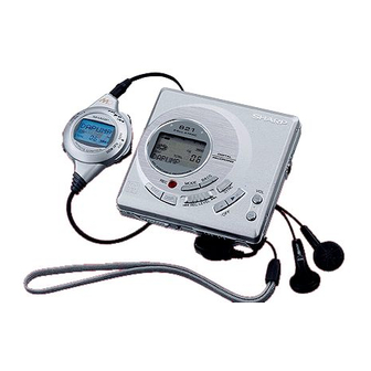
Illustration: MD-MT821
Illustration: MD-MT821W
SAFETY PRECAUTION FOR SERVICE MANUAL (MD-MT821W ONLY) ............................................................................ 2
SPECIFICATIONS ................................................................................................................................................................. 3
NAMES OF PARTS ............................................................................................................................................................... 4
OPERATION MANUAL .......................................................................................................................................................... 5
QUICK GUIDE (MD-MT821 ONLY) ....................................................................................................................................... 8
DISASSEMBLY .................................................................................................................................................................... 10
REMOVING AND REINSTALLING THE MAIN PARTS ....................................................................................................... 11
ADJUSTMENT ...................................................................................................................................................................... 12
NOTES ON SCHEMATIC DIAGRAM .................................................................................................................................. 28
BLOCK DIAGRAM ............................................................................................................................................................... 29
SCHEMATIC DIAGRAM/WIRING SIDE OF P.W.BOARD ................................................................................................... 30
WAVEFORMS OF MD CIRCUIT ......................................................................................................................................... 37
TROUBLE SHOOTING ........................................................................................................................................................ 38
FUNCTION TABLE OF IC .................................................................................................................................................... 41
PARTS GUIDE/EXPLODED VIEW
SERVICE MANUAL
CONTENTS
SHARP CORPORATION
- 1 -
MD-MT821(GL)
MD-MT821W(BL)
MD-MT821W(GL)
• In the interests of user-safety the set should be restored to its
original condition and only parts identical to those specified be
used.
This document has been published to be used
for after sales service only.
The contents are subject to change without notice.
MD-MT821/W
No. S4913MDMT821/
Page
Advertisement
Table of Contents

Related Manuals for Sharp MD-MT821(GL)


Summary of Contents for Sharp MD-MT821(GL)
-
Page 1: Table Of Contents
FUNCTION TABLE OF IC ..............................41 PARTS GUIDE/EXPLODED VIEW PACKING OF THE SET (MD-MT821 ONLY) This document has been published to be used SHARP CORPORATION for after sales service only. The contents are subject to change without notice. – 1 –... -
Page 2: Safety Precaution For Service Manual (Md-Mt821W Only)
MD-MT821/W SAFETY PRECAUTION FOR SERVICE MANUAL (MD-MT821W ONLY) Precaution to be taken when replacing and servicing the CAUTION Laser Pickup. The AEL (Accessible Emission Level) of Laser Power Output for this model is specified to be lower than Class I Require- ments. -
Page 3: Specifications
MD-MT821/W FOR A COMPLETE DESCRIPTION OF THE OPERATION OF THIS UNIT, PLEASE REFER TO THE OPERATION MANUAL. SPECIFICATIONS General Output level: Specified Maximum Load Power source: DC 3.6 V : Rechargeable lithium-ion (MT821) output output level impedance (MT821) battery x 1 Headphones —... -
Page 4: Names Of Parts
MD-MT821/W NAMES OF PARTS Remote control unit 1. Synchro Recording Indicator 2. Character/Time Information Indicator SYNC RANDOM 3. Record Indicator TOTAL 4. Repeat Indicator: 5. Random Indicator 6. Disc Mode Indicator 7. Total Track Number Indicator 8. Track Number Indicator 9. -
Page 5: Operation Manual
MD-MT821/W OPERATION MANUAL – 5 –... - Page 6 MD-MT821/W – 6 –...
- Page 7 MD-MT821/W – 7 –...
-
Page 8: Quick Guide (Md-Mt821 Only)
MD-MT821/W QUICK GUIDE (MD-MT821 ONLY) – 8 –... - Page 9 MD-MT821/W – 9 –...
-
Page 10: Disassembly
MD-MT821/W DISASSEMBLY Cares before disassembling (B1)x2 (A1)x1 When assembling the machine after disassembling or ø1.4x2mm ø1.4x2mm repair, observe the following requirements so as to ensure safety and performance. 1. Remove the batteries from the machine, and take out the (A1)x2 mini-disc. -
Page 11: Removing And Reinstalling The Main Parts
MD-MT821/W REMOVING AND REINSTALLING THE MAIN PARTS (A2)x3 Remove the mechanism according to the disassembling meth- ø1.4x2.8mm ods 1 to 6. (See Page 10.) How to remove the spindle motor (See Fig. 11-1.) 1. Remove the solder joint (A1) x 1 of flexible PWB. Spindle Motor Mechanism Flexible 2. -
Page 12: Adjustment
MD-MT821/W ADJUSTMENT Test disc MD adjustment needs two types of disc, namely recording disc (low reflection disc) and playback-only disc (high reflection disc). Type Test disc Parts No. High reflection disc MMD-110 (TEAC Test MD) 88GMMD-110 Low reflection disc MMD-212 (TEAC Test MD) 88GMMD-212 Low reflection disc Recording minidisc... - Page 13 MD-MT821/W Operation in each TEST mode 1. AUTO1 Mode • When the STOP button is pressed while the AUTO1 menu appears or during automatic adjustment, the mode changes to the TEST mode stop state. At this time the adjustment value is not output. •...
- Page 14 MD-MT821/W • When the SKIP UP button is pressed in the continuous playback mode, the specified number of lines is jumped in the FWD direction. • When the SKIP DOWN button is pressed in the continuous playback mode, the specified number of lines is jumped in the REV direction. * When the SKIP UP/DOWN button is held down, jump is repeated every approx.
- Page 15 MD-MT821/W 44h : U-TOC write data write disabled/read check error 52h : SD write data write disabled 71h : Pickup position initialization time-over 72h : EEPROM data read check sum error 73h : Record head drive disabled (by EJECT lever) 82h : Power overvoltage detection 91h : Ambient temperature is higher that the allowable temperature.
- Page 16 MD-MT821/W EEPROM DATA LIST (EEPROM version d) Sled setting TEMP setting Item display Set values Item display Set values S L G _ T M _ _ Calculate values S L 2 _ Fucus setting S L M _ Item display Set values S L V _ F G _ _...
- Page 17 MD-MT821/W – 17 –...
- Page 18 MD-MT821/W – 18 –...
- Page 19 MD-MT821/W – 19 –...
- Page 20 MD-MT821/W – 20 –...
- Page 21 MD-MT821/W – 21 –...
- Page 22 MD-MT821/W – 22 –...
- Page 23 MD-MT821/W – 23 –...
- Page 24 MD-MT821/W – 24 –...
- Page 25 MD-MT821/W – 25 –...
- Page 26 MD-MT821/W – 26 –...
- Page 27 MD-MT821/W – 27 –...
-
Page 28: Notes On Schematic Diagram
MD-MT821/W NOTES ON SCHEMATIC DIAGRAM • Resistor: • The indicated voltage in each section is the one measured To differentiate the units of resistors, such symbol as K and by Digital Multimeter between such a section and the chas- M are used: the symbol K means 1000 ohm and the symbol sis with no signal given. -
Page 29: Block Diagram
MD-MT821/W +2.5V AVCC Figure 29 BLOCK DIAGRAM – 29 –... -
Page 30: Schematic Diagram/Wiring Side Of P.w.board
MD-MT821/W P31 P32 MAIN PWB-A C112 0.033 C111 C110 TP139 0.0033 C107 0.22 0.012 C109 CK112 C106 PLAYBACK SIGNAL 0.22 RECORD SIGNAL 48 47 46 45 44 43 42 41 40 39 38 37 C211 R222 ROUT ADAGC R106 5P(CH) ADIPI EFMAGI ADIPO... - Page 31 MD-MT821/W DADATA TP451 ADDATA TP139 TP452 DFCK TP453 BCLK TP454 LRCK HREC TP455 C211 TP456 ADPON R222 5P(CH) HSTOP TP457 DAPON TP458 OPTCNT HPLAY TP459 HKEY2 TP461 HKEY1 R455 R456 R457 R458 TP462 IC202 IX2723AF Serrial 903xxxxx XL201 TP211 5.6K 8.2K R451 R452...
- Page 32 MD-MT821/W LCD ASS'Y KEY SWITCH FLEXIBLE PWB ASS'Y DADATA TP451 ADDATA EDIT TP452 DFCK DISPLAY TP453 BCLK SKIP DOWN TP454 LRCK SKIP UP HREC TP455 TP456 ADPON MODE HSTOP TP457 DAPON STOP TP458 OPTCNT VOLUME DOWN HPLAY TP459 PLAY HKEY2 TP461 BASS HKEY1...
- Page 33 MD-MT821/W IC101 IC201 IC401 IC501 IC701 IC830 VOLTAGE PIN VOLTAGE PIN VOLTAGE VOLTAGE VOLTAGE VOLTAGE VOLTAGE VOLTAGE 0.4V 0.88V 2.51V 1.25V 0.4V 2.5V 2.5V 2.51V 1.23V 2.37V 2.37V 0.4V 1.27V 0.4V 2.35V 1.22V 1.25V 1.25V 2.34V 1.25V 1.26V 1.25V 1.06V 0.4V 2.37V 1.26V...
- Page 34 MD-MT821/W MAIN PWB-A (BOTTOM VIEW) J702 MIC IN J801 DC Jack C872 L871 C805 C871 IC701 C806 C841 R812 R872 R800 C800 C703 R703 D802 R842 C701 C842 C702 R843 D804 R702 D800 R815 R711 R811 R804 R816 C856 R810 R801 IC801 Q841...
- Page 35 MD-MT821/W MAIN PWB-A(TOP VIEW) To Key Switch Flexible Ass'y To LCD Ass'y P36 2-E P36 5-E J702 J801 MIC IN DC Jack TP459 TP457 TP455 TP453 TP451 TP485 TP711 TP462 TP712 TP481 TP484 TP483 TP482 TP463 TP461 TP458 TP452 Terminal ,Battery – L711 (213) L802...
- Page 36 MD-MT821/W Magnetic Head Flexible PWB (23) M901 Spindle Motor Optical Pickup Unit (15) Magnetic Head (30) SW902 Disc Mechanism Flexible Protect PWB Ass'y (8) PH901 CN601 Phote To Main PWB Interrupter P35 10-H M902 Sled Motor CN101 M903 To MAIN PWB Lift Motor P35 7-H To MAIN PWB...
-
Page 37: Waveforms Of Md Circuit
MD-MT821/W WAVEFORMS OF MD CIRCUIT Stopped 1994 / 12 / 15 22:54:19 Stopped 1994 / 12 / 16 00:24:17 Stopped 1994 / 12 / 16 01:03:40 CH1=1mV CH2=500mV CH3=5V CH4=2V 50ms/div CH1=2V CH2=2V CH3=2V CH4=2V 50us/div CH1=1V CH2=2V CH3=500mV 2ms/div DC 10:1 DC 10:1 DC 10:1... -
Page 38: Trouble Shooting
MD-MT821/W TROUBLE SHOOTING It is advisable to use the TEST mode (refer to Error Data Display Mode, P13) indicating the causes of troubles before starting repair. Causes of operation errors (up to 10 errors) are recorded as error codes. This information is useful for repair. - Page 39 MD-MT821/W • Abnormal display Is waveform output from CN482 pins 1 to 3? Is waveform output from IC401 pins 9,10,13? Are the pin7 (VCC) and pin 6 (GND) normal? Check the periphery of IC401. Check between IC401 and CN482. Check for pattern breakage of flexible PWB, check for defects of display microcomputer (replace the display unit).
- Page 40 MD-MT821/W • The spindle motor fails to run.Does the head move Check the IC201 periphery. Does the waveform appear on the IC201 pins 24 and 25 after TEST mode AUTO2 completion and in this state? Replace. IC601 Does waveform appear on the IC601 pin 13? Does waveform appear on IC901 pins 1, 19 and 20? L608, IC201, IC901, CN601 and flex, etc.
-
Page 41: Function Table Of Ic
MD-MT821/W FUNCTION TABLE OF IC IC401 RH-iX2792AF02(IX2792AF):System Microcomputer (1/2) Port Name Terminal Name Input/Output Function Pin No. P12/TCLKA Input Track cross signal/focus drive detection TCLKB SPIN Input Spindle motor FG pulse detection input Output (not used) DISCPR Input Disc record inhibition switch input TIOCA2 SPWDS Input... - Page 42 MD-MT821/W IC401 RH-iX2792AF02(IX2792AF):System Microcomputer (2/2) Port Name Terminal Name Input/Output Function Pin No. Input Operation mode selection input 1 INNSW Input Mechanism inner SW position detection input WDTOVF WDTOVF Output Watch dog timer (not used) Input Operation mode selection input 2 _RESET Input Microcomputer hard reset input...
- Page 43 “HOW TO ORDER REPLACEMENT PARTS” To have your order filled promptly and correctly, please furnish the For U.S.A. only following information. Contact your nearest SHARP Parts Distributor to order. 1. MODEL NUMBER 2. REF. No. 3. PART NO. 4. DESCRIPTION For location of SHARP Parts Distributor, Please call Toll-Free;...
- Page 44 MD-MT821/W PRICE PRICE PARTS CODE DESCRIPTION PARTS CODE DESCRIPTION RANK RANK INTEGRATED CIRCUITS L751,752 VPBNN100M0000 AC 10 H L771 RCILC0359AFZZ AC 100 H,Choke L821 RCILC0282AFZZ AC 22 H,Choke IC101 VHIIR3R55//-1 AQ RF Signal,Processor,IR3R55 L851 RCILC0332AFZZ AC 4.7 H,Choke IC200 VHI62FP2502-1 AE Power Drive,62FP2002 L852 RCILC0333AFZZ...
- Page 45 MD-MT821/W PRICE PRICE PARTS CODE DESCRIPTION PARTS CODE DESCRIPTION RANK RANK C765,766 RC-KZ1205AFZZ AB 0.33 F,10V R481,482 VRN-CY1JD333D AA 33 kohms,1/16W,1%,Metal Film C771 VCSATE0JJ476M AD 47 F,6.3V,Electrolytic,Tantalum R492 VRS-CY1JB102J AA 1 kohm,1/16W C773 RC-KZ1204AFZZ AB 0.22 F,10V R500 VRS-CY1JB4R7J AA 4.7 ohms,1/16W C774 VCKYTV1CF105Z AB 1 F,16V...
- Page 46 MD-MT821/W PRICE PRICE DESCRIPTION PARTS CODE PARTS CODE DESCRIPTION RANK RANK J703 QJAKM0205AFZZ AH Jack,Remote Control/Head- PSHEZ1022AFZZ AB Sheet,Extension Battery phones Terminal J801 QJAKC0142AFZZ AE Jack,DC QTANB9401AFFQ AC Terminal,Battery + M901 RMOTV0524AFZZ AS Motor Ass'y [Spindle] QTANB9402AFFQ AB Terminal,Battery - M902 RMOTV0511AFZZ AT Motor Ass'y [Sled]...
- Page 47 MD-MT821/W PRICE PRICE PARTS CODE DESCRIPTION PARTS CODE DESCRIPTION RANK RANK TINSZ1393AFZZ AH Operation Manual [MT821] TINSZ1394AFZZ AE Quick Guide [MT821 Only] TINSZ1395AFZZ AR Operation Manual [MT821W] TLABG0527AFZZ AC Label,Hong Kong [MT821W for Hong Kong] TLABG0527AFZ1 AC Label,Hong Kong [MT821W for Hong Kong] TLABH0699AFZZ Label,Translation [MT821W for Taiwan]...
- Page 48 MD-MT821/W 501x2 509x2 8-3(PH901) (SW902) 502x3 M901 M903 503x2 M902 Figure 5 MD MECHANISM EXPLODED VIEW – 5 –...
- Page 49 MD-MT821/W MD MECHANISM 603x2 238x2 603x2 210x2 For MT821W Only PWB-A 204-4 204-2 603x2 For MT821W Only 204-1 204-3 603x2 Figure 6 CABINET EXPLODED VIEW – 6 –...
-
Page 50: Packing Of The Set (Md-Mt821 Only)
MD-MT821/W PACKING OF THE SET (MD-MT821 ONLY) SETTING POSITION OF SWITCHES AND KNOBS UNIT HOLD Remote Control HOLD CANSEL Connecting Cord, Optical Type Caution, Headphones Lid Battery Attention Card Operation Manual Remote Control Rechargeable, Battery Battery Case Quick Guide Carrying Case AC Adaptor Strap Headphones... - Page 51 MD-MT821/W — M E M O — – 8 –...
- Page 52 MD-MT821/W © COPYRIGHT 1999 BY SHARP COPORATION ALL RIGHTS RESERVED. No part of this publication may be reproduced, stored in a retrieval system, or transmitted in any from or by any means, electronic, mechanical, photocopying, recording, or otherwise, without prior written permission of the publisher.
Need help?
Do you have a question about the MD-MT821(GL) and is the answer not in the manual?
Questions and answers