
Related Manuals for CyberGuard SnapGear

Summary of Contents for CyberGuard SnapGear
- Page 1 SnapGear Firewall VPN Appliance User Manual Revision 1.9.1 March 12, 2004 SnapGear – A CyberGuard Company 7984 South Welby Park Drive #101 Salt Lake City, Utah 84084 Email: support@snapgear.com Web: www.snapgear.com...
-
Page 2: Table Of Contents
SnapGear PCI Appliance Features ..............10 Getting Started ..................11 SnapGear Gateway Appliances .................11 Set up a PC to Connect to the SnapGear Management Console .......11 Set up the SnapGear Appliance’s Password and LAN Connection Settings..14 Set up the SnapGear Appliance’s Internet Connection Settings ......17 Set up the PCs on your LAN to Access the Internet ...........18... - Page 3 Virtual Private Networking..............101 PPTP Client Setup ................... 102 PPTP Server Setup..................104 IPSec Setup..................... 115 Configuring the Branch Office SnapGear Appliance......... 115 Configuring the Headquarters SnapGear Appliance......... 129 Tunnel List ....................... 133 NAT Traversal Support ..................137 Dynamic DNS Support..................137 Certificate Management ...................
- Page 4 10. System ....................156 Date and Time ....................156 Users ....................... 158 Diagnostics ...................... 161 Advanced......................163 Technical Support .................... 166 Appendix A – IP Address Ranges ............... 167 Appendix B – Terminology ................168 Appendix C – System Log ................175 Access Logging....................
-
Page 5: Introduction
VPN enables remote workers or branch offices to securely access your company network to send and receive data at a very low cost. With the SnapGear appliance, you can remotely access your office network securely using the Internet. The SnapGear appliance can also connect to external VPNs as a client. -
Page 6: Snapgear Pci Appliances
For environments where the integrity of the host server operating environment cannot be controlled or trusted. Unlike SnapGear gateway appliances, a single SnapGear PCI appliance it is not intended as a means for your entire office LAN to be connected to, and shielded from, the Internet. - Page 7 (DHCP) or statically configured to use the same gateway, DNS, etc. settings as a regular PC on the LAN. It is possible to configure the SnapGear appliance to run in NAT mode. This is discussed in the chapter entitled Network Connections.
-
Page 8: Document Conventions
Document Conventions This document uses different fonts and typefaces to show specific actions. Warning/Note Text like this highlights important issues. Bold text in procedures indicates text that you type, or the name of a screen object (e.g. a menu or button). Introduction... -
Page 9: Your Snapgear Gateway Appliance
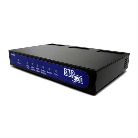
Your SnapGear Gateway Appliance SnapGear gateway appliances include: SME530 SME550 SME570 SME575 The following items are included with your SnapGear gateway appliance: Power adaptor Installation CD Printed Quick Install guide Cabling including o 1 normal straight through UTP cable (blue color) - Page 10 Note Not all the LEDs described below are present on all SnapGear appliance models. Also, labels vary from model to model. Label Activity Description Power Power is supplied to the SnapGear appliance Heart Beat Flashing The SnapGear appliance is operating correctly...
- Page 11 Rear panel The rear panel contains the connector ports for the LAN, Internet, modem (COM1) and possibly DMZ (SME570, SME575 only) as well as LAN status LEDs, Internet status LEDs, the reset button and power inlet. The lower LAN/Internet status LED indicates the link condition, where a cable is connected correctly to another device.
-
Page 12: Snapgear Gateway Appliance Features
SnapGear Gateway Appliance Features Internet link features 10/100baseT Ethernet port (Internet/WAN) that connects to the Internet using a cable or ADSL modem Serial port to attach an external modem or ISDN TA Front panel serial status LEDs (for TX/RX) Online status LEDs (for Internet/VPN) -
Page 13: Your Snapgear Pci Appliance
Your SnapGear PCI Appliance SnapGear PCI appliances include: PCI630 PCI635 The following items are included with your SnapGear PCI appliance: Installation CD Printed Quick Install guide LEDs The rear panel contains LEDs indicating status. The two LEDs closest to the network port are network activity (upper) and network link (lower). -
Page 14: Snapgear Pci Appliance Features
SnapGear PCI Appliance Features Network link features 10/100baseT Ethernet port that connects to the LAN (or Internet using a cable or ADSL modem) Ethernet LEDs (link, activity) Environmental features Status LEDs: Power, Heart Beat Operating temperature between 0° C and 40° C Storage temperature between -20°... -
Page 15: Getting Started
These instructions assume you have a PC running Microsoft Windows (95/98/Me/ 2000/XP for SnapGear gateway appliances, 2000/XP only for SnapGear PCI appliances). If you are installing a SnapGear gateway appliance, you must have an Ethernet network interface card installed. You may need to be logged in with administrator privileges. - Page 16 The SnapGear appliance’s LAN interface will always be initially reachable at 192.168.0.1. If you attach your SnapGear unit directly to a LAN with an existing DHCP server before performing the initial setup steps described below, the LAN interface will automatically obtain an additional address.
- Page 17 Note If there is more than one existing network connection, select the one corresponding to the network interface card to which the SnapGear appliance is attached. Select Internet Protocol (TCP/IP) and click Properties (or in 95/98/Me, TCP/IP -> your network card name if there are multiple entries) and click Properties.
-
Page 18: Set Up The Snapgear Appliance's Password And Lan Connection Settings
2 seconds returns the SnapGear appliance to its factory default settings. Enter and confirm a password for your SnapGear appliance. This is the password for the user root, the main administrative user account on the SnapGear appliance. It is therefore important that you choose a password that is hard to guess, and keep it safe. - Page 19 The Quick Setup Wizard will display. Figure 2-3 Hostname: You may change the name the SnapGear appliance knows itself by. This is not generally necessary. Manual configuration: Select this to manually specify your SnapGear appliance’s LAN connection settings. Skip: LAN already configured: Select this if you wish to use the SnapGear appliance’s initial network settings (IP address 192.168.0.1 and subnet mask 255.255.255.0) as a...
- Page 20 Enter an IP address and Subnet mask for your SnapGear appliance’s LAN connection. You may choose to use the SnapGear appliance’s initial network settings if you are sure no other PC or network device already has the address of 192.168.0.1.
-
Page 21: Set Up The Snapgear Appliance's Internet Connection Settings
Set up the SnapGear Appliance’s Internet Connection Settings Select your Internet connection type and click Next. Figure 2-5 Cable modem If connecting using a cable modem, select the appropriate ISP. Choose Generic cable modem provider if unsure. Analog modem If connecting using a regular analog modem, enter the details provided by your ISP. -
Page 22: Set Up The Pcs On Your Lan To Access The Internet
LAN hub using the straight through Ethernet cable (blue). To access the Internet, the PCs on your network must all be set up to use the SnapGear appliance as their default gateway. This can be done a number of different ways depending on how your LAN is set up. - Page 23 A DHCP server allows PCs to automatically obtain network settings when they start up. If your network does not have a DHCP server, you may either manually set up each PC on your network, or set up the SnapGear appliance's DHCP server. Note If you only have several PCs, we suggest manually setting up your network.
- Page 24 Default Lease Time and Maximum Lease Time should generally be left at their default values. Initial Dynamic IP Address Range is a range of free IP addresses on your LAN’s subnet for the SnapGear appliance to hand out to PCs on your LAN. Getting Started...
- Page 25 Note For a detailed description of configuring DHCP Server Settings, please refer to the User Manual. Each PC on your LAN must now be set up to use DHCP. For each PC on your LAN: Click Start -> Settings -> Control Panel and double click Network Connections (or in 95/98/Me, double click Network).
-
Page 26: Snapgear Pci Appliances
PC and the LAN transparently filtering network traffic. If you want to set up the SnapGear appliance for NAT mode or to connect directly to your ISP, refer to the chapter entitled Network Connections. - Page 27 Next, you must modify your PC’s network settings to enable it to communicate with the SnapGear appliance. Click Start -> Settings -> Control Panel and double click Network Connections. Right click on Local Area Connection (or appropriate network connection for the newly installed PCI appliance) and select Properties.
-
Page 28: Set Up The Snapgear Appliance's Password And Network Connection Settings
SnapGear appliance to its factory default settings. Enter and confirm a password for your SnapGear appliance. This is the password for the user root, the main administrative user account on the SnapGear appliance. It is therefore important that you choose a password that is hard to guess, and keep it safe. - Page 29 Locate the Bridge / br0 port and select Edit current settings under Configuration. If your LAN has an active DHCP server, you may set up your SnapGear appliance and PC for auto-configuration. Otherwise you must manually set up your SnapGear appliance’s and PC’s network settings.
- Page 30 Click Apply and Reboot. Next, configure your PC with the second IP address in the same manner you would as if it were connected directly to the LAN. Click Start -> Settings -> Control Panel and double click Network Connections. Right click on Local Area Connection (or appropriate network connection for the newly installed PCI appliance) and select Properties.
- Page 31 SnapGear Management Console, the other for your PC. Note It is highly recommended that you reserve the IP address to be used by the SnapGear Management Console using the SnapGear appliance’s MAC address. In bridged mode, this will be the top MAC address of the three displayed on the SnapGear appliance itself.
- Page 32 Check Obtain an IP address automatically, check Obtain DNS server address automatically and click OK. Attach your SnapGear appliance’s Ethernet port to your LAN’s hub. If you cannot connect to PCs on your LAN, reboot your PC. You are now finished.
-
Page 33: Disabling The Reset Button On Your Snapgear Pci Appliance
Disabling the Reset Button on your SnapGear PCI Appliance For convenience, the SnapGear appliance ships with the rear panel Reset button enabled. This allows the SnapGear appliance’s configuration to be reset to factory defaults. From a network security standpoint, it may be desirable to disable the Reset switch after initial setup has been performed. -
Page 34: Network Connections
DMZ connection, remote dialin access or Internet failover. If you are using a SnapGear gateway appliance, the section Set up the PCs on your LAN to access the Internet in the chapter entitled Getting Started describes how to configure the PCs on your LAN to share the connection once your Internet connection has been established. -
Page 35: Lan
IP range, such as 192.168.0.1 / 255.255.255.0. Ensure DHCP assigned is unchecked. If you wish to have your SnapGear appliance obtain its LAN network settings from an active DHCP server on your local network, check DHCP assigned then Apply. Note that anything in the IP Address and Netmask fields will be ignored. -
Page 36: Internet
The unit will take up to 30 seconds longer than normal to reboot after bridging has been enabled. Internet The SnapGear appliance can connect to the Internet using an external dialup analog modem, an ISDN modem, a permanent analog modem, a cable modem or DSL link. Figure 3-3... -
Page 37: Internet Connection Methods
Connect your SnapGear appliance‘s Internet port to the modem device using a straight through Ethernet cable. Apply power to the modem device and give it some time to power up. If fitted, ensure the Ethernet link LEDs are illuminated on both the SnapGear appliance and modem device. - Page 38 PCs on the LAN are trying to reach the Internet by checking the Connect on Demand box. If you are connecting on demand, enter an Idle Disconnect Time. This is the time (in minutes) that the SnapGear appliance will wait before disconnecting when the connection is idle.
- Page 39 You may configure this interface with an IP address. This IP address will be used primarily for accessing the SnapGear appliance management console, and does not necessarily have to be part of the networks that the SnapGear appliance is being used to bridge between.
-
Page 40: Com/Modem
To connect to an ISDN line, the SnapGear appliance requires an intermediate device called a Terminal Adapter (TA). A TA connects into your ISDN line and has either a serial or Ethernet port that is connected to your SnapGear appliance. Do not plug an ISDN connection directly in to your SnapGear appliance. - Page 41 ISP gateway in Remote IP Address. If a connect of demand connection has been set up, Connect Now/Disconnect Now buttons will be displayed. These make the SnapGear appliance dial or hang up the modem connection immediately. Network Connections...
-
Page 42: Dmz
Services on the DMZ Network Once you have configured the DMZ connection, you will also want to configure the SnapGear appliance to allow access to services on the DMZ. There are two methods of allowing access. If the servers on the DMZ have public IP addresses, you need to add packet filtering rules to allow access to the services. -
Page 43: Load Balancing
However, you can also create custom packet filtering rules if you wish to restrict access to the services. You may also want to configure your SnapGear appliance to allow access from servers on your DMZ to servers on your LAN. By default, all network traffic from the DMZ to the LAN is dropped. -
Page 44: Internet Failover
Internet Failover Internet failover is available on SnapGear gateway appliances only. SnapGear appliances are designed with the real Internet in mind, which may mean downtime due to ISP equipment or telecommunications network failure. Failures can be caused by removing the wrong plug from the wall, typing in the wrong ISP password or many other reasons. - Page 45 Figure 3-6 Enter the IP address of this host in IP Address to ping. Ping Interval is the number of seconds to wait between sending pings. Number of times to attempt this connection is the number of failed attempts before this connection is considered failed.
-
Page 46: Routes
Routes Additional routes The Additional routes feature allows expert users to add additional static routes for the SnapGear appliance. These routes are additional to those created automatically by the SnapGear appliance configuration scripts. Route management Your SnapGear appliance can be configured to automatically exchange routing information with other routers. -
Page 47: Advanced
The Hostname is a descriptive name for the SnapGear appliance on the network. DNS Proxy The SnapGear appliance can also be configured to run as a Domain Name Server. The SnapGear appliance acts as a DNS Proxy and passes incoming DNS requests to the appropriate external DNS server. - Page 48 Figure 3-9 Network Address Translation (NAT/masquerading) The SnapGear appliance can utilize IP Masquerading (a simple form of Network Address Translation, or NAT) where PCs on the local network effectively share a single external IP address. Masquerading allows insiders to get out, without allowing outsiders in. By default, the Internet port is setup to masquerade.
- Page 49 TZO.com and dyndns.org can register an Internet domain name that will point to your Internet IP address no matter how often it changes. Whenever its Internet IP address changes, the SnapGear appliance will alert the dynamic DNS service provider so the domain name records can be updated appropriately.
- Page 50 Figure 3-10 Interface aliases Interface aliases allow the SnapGear appliance to respond to multiple IP addresses on its LAN, Internet and DMZ ports. For Internet and DMZ aliased ports, you must also setup appropriate Packet Filtering and/or Port forwarding rules to allow traffic on these ports to be passed onto the local network.
-
Page 51: Qos Traffic Shaping
Address of your SnapGear appliance. The MAC address is a globally unique address and is specific to a single SnapGear appliance. It is set by the manufacturer and should not normally be changed. However, you may need to change it if your ISP has configured your ADSL or cable modem to only communicate with a device with a known MAC address. -
Page 52: Dialin Setup
SnapGear appliance. The SnapGear appliance’s dialin facility establishes a PPP connection to the remote user or site. Dialin requests are authenticated by usernames and passwords verified by the SnapGear appliance. -
Page 53: Dialin Setup
Dialin Setup Once an analog modem or phone line has been attached, enable the SnapGear appliance’s COM port or internal modem for dialin. Under Networking, select Network Setup. From the Connections menu, locate the COM port or Modem on which you want to enable dialin, and select Change to Dialin Access from the Configuration pull down menu. - Page 54 15 minutes. Idle time can be set between 0 – 99 minutes. After enabling and configuring the selected SnapGear appliance COM ports/Modem to support dialin, click Continue to create and configure the dialin user accounts.
-
Page 55: Dialin User Accounts
Dialin User Accounts User accounts must be set up before remote users can dialinto the SnapGear appliance. The following figure shows the Dialin user account creation: Figure 4-2 The field options in Add New Account are shown in the following table:... - Page 56 The following figure shows the user maintenance screen: Figure 4-3 Dialin Setup...
- Page 57 When you have finished adding and modifying user account details, you can configure other SnapGear appliance functions by selecting the appropriate item from the Network or System menus. You can also apply packet filtering to the dialin service as detailed in the chapter entitled Firewall.
-
Page 58: Remote User Configuration
Warning If you have enabled a SnapGear appliance COM port/Modem for dialin, this port cannot be used simultaneously for dial-out activities (e.g. dial-on-demand Internet connection). If a port is set-up for Internet access, and is later enabled for dial-in, the Internet access function is automatically disabled. - Page 59 Figure 4-5 Check the Log on to network and Enable software compression checkboxes. If your SnapGear appliance dialin server requires MSCHAP-2 authentication, you also need to check the Require encrypted password checkbox. Leave all other Advanced Options unchecked.
- Page 60 Dialin and log on to the remote SnapGear appliance by double-clicking the Connection Name icon. You need to enter the Username and the Password that was set up for the SnapGear appliance dial-in account. Windows 2000/XP To configure a remote access connection on a PC running Windows 2000/XP, click Start, Settings, Network and Dial-up Connections and select Make New Connection.
- Page 61 Click Next to continue. Figure 4-7 Select Dial-up to private network as the connection type and click Next to continue. Figure 4-8 Tick Use dialing rules to enable you to select a country code and area code. This feature is useful when using remote access in another area code or overseas. Dialin Setup...
- Page 62 Click Next to continue. Figure 4-9 Select the option Only for myself to make the connection only available for you. This is a security feature that will not allow any other users who log onto your machine to use this remote access connection: Figure 4-10 Enter a name for the connection and click Finish to complete the configuration.
- Page 63 If you did not create a desktop icon, click Start, Settings, Network and Dial-up Connections and select the appropriate connection and enter the username and password set up for the SnapGear appliance dialin account.
-
Page 64: Dhcp Server
5. DHCP Server Your SnapGear appliance can act as a DHCP server for machines on your local network. To configure your SnapGear appliance as a DHCP server, you must set a static IP address and netmask on the LAN or DMZ port (see the chapter entitled Network Connections). - Page 65 Enter the DNS Address that the DHCP clients will be issues with. If this field is left blank, the SnapGear's IP address will be used. Leave this field blank for automatic DNS server assignment. If your SnapGear appliance is configured for DNS masquerading, you should either leave this field blank, or enter the IP address of the LAN port of the SnapGear appliance.
- Page 66 Subnet List The Subnet List will display the status of the DHCP server. Interface Once a subnet has been configured, the port which the IP addresses will be issued from will be shown in the Interface field. Subnet The value shown in this field is the subnet for which the IP addresses distributed will use. Free Addresses This field will contain the number of remaining available IP addresses that can be distributed.
- Page 67 Figure 5-3 For each IP address that the DHCP server services, the Status, Hostname, MAC Address will be shown. There is also be an option to Remove the address and for reserved IP addresses, the added option to Unreserve the address. Unreserving the address will allow it to be handed out to any host.
-
Page 68: Dhcp Proxy
DHCP Proxy The DHCP proxy allows the SnapGear unit forward DHCP requests from the LAN to an external server for resolution. This allows both static and dynamic addresses to be given out on the LAN just as running a DHCP server would. -
Page 69: Firewall
6. Firewall The SnapGear appliance has a fully featured, stateful firewall. The firewall allows you to control both incoming and outgoing access, so that PCs on the office network can have tailored Internet access facilities and are shielded from malicious attacks. - Page 70 The following figure shows the Administration Services page: Figure 6-1 By default the SnapGear appliance runs a web administration server and a telnet service. Access to these services can be restricted to specific interfaces. For example, you may want to restrict access to the SnapGear Management Console web administration pages (Web Admin) to machines on your local network.
-
Page 71: Snapgear Web Server
SnapGear Web Server Clicking the SnapGear Web Server tab takes you to the page to configure the administrative web server. This web server is responsible for running the SnapGear Management Console. Here you can change the port on which the server runs. Additionally, the SME550,... - Page 72 The SnapGear Management Console is usually accessed on the default HTTP port (i.e. port 80). After changing the web server port number, you must include the new port number in the URL to access the pages. For example, if you change the web administration to port number 88, the URL to access the web administration will be similar to: http://192.168.0.1:88...
- Page 73 Generating certificates is not immediate, and usually takes a few minutes. Exact time will depend on the model of SnapGear appliance you have and the key size being generated. You can tell when the certificates are created, the line Valid SSL certificates have been uploaded will read Yes when the previous page is refreshed.
-
Page 74: Packet Filtering
The most common use of this is for port forwarding (aka PAT/Port Address Translation) from ports on the SnapGear WAN interface to ports on machines on the LAN side. This is the most common way for internal, masqueraded servers to offer services to the outside world. - Page 75 To define an address using the DNS hostname, enter the DNS hostname in the Name field, and leave the IP Address field empty. The SnapGear appliance will perform a DNS lookup, and fill in the IP Address field. If the DNS hostname is invalid, you may need to wait while the DNS lookup times out.
- Page 76 Service groups Click the Service Groups tab. Any addresses that have already been defined will be displayed. Click New to add a new service groups, or select an existing address and click Modify. Adding or modifying a service group is shown in the following figure: Figure 6-5 A service group can be used to group together similar services.
- Page 77 Rules Once addresses and services have been defined, you can create filter rules. Click Rules. Any rules that have already been defined will be displayed. Click New to add a new filter rule, or select an existing filter and click Modify. Note The first matching rule will determine the action for the network traffic, so the order of the rules is important.
-
Page 78: Nat
Port forwarding allows controlled access to services provided by machines on your private network to users on the Internet by forwarding requests for a specific service coming into one of the SnapGear appliance’s interfaces (typically the WAN interface) to a machine on your LAN, which services the request. - Page 79 Source NAT alters the source address and optionally the source port of packets received by the SnapGear appliance. This is typically used for masquerading. You can use the Source NAT functionality of Packet Filtering to tweak your SnapGear appliance’s masquerading behaviour.
- Page 80 To Source Address The address to replace the Source Address (for masquerading this will typically be a public address of the SnapGear appliance, i.e. WAN/Internet) To Source Service The service to replace Source Services, this need not be the same as the Source Service used to...
-
Page 81: Rules
To access this page, click Rules in the Firewall menu. Only experts on firewalls and iptables rules will be able to add effective custom firewall rules. Configuring the SnapGear firewall via the Incoming Access and Outgoing Access configuration pages is adequate for most applications. -
Page 82: Access Control And Content Filtering
Inappropriate Internet use during work hours can have a serious effect on productivity. With the SnapGear Access Control web proxy, you can control access to the Internet based on the type of web content being accessed (Content), and which user or workstation is accessing the Internet content (Require user authentication, IP Lists). - Page 83 Users without web proxy access will see a screen similar to the figure below when attempting to access external web content. Figure 6-8 Note Each browser on the LAN will now have to be set up to use the SnapGear appliance’s web proxy. Firewall...
- Page 84 Browser setup The example given is for Microsoft Internet Explorer 6. Instructions for other browsers should be similar, refer to their user documentation for details on using a web proxy. From the Internet Options menu, select Tools. From the LAN Settings tab, select LAN Settings.
- Page 85 Figure 6-10 In the row labeled HTTP, enter your SnapGear appliance’s LAN IP address in the Proxy address to use column, and 81 in the Port column. Leave the other rows blank. In the Exceptions text box, enter your SnapGear appliance’s LAN IP address.
- Page 86 Web lists Access will be denied to any web address (URL) that contains text entered in the Block List, e.g. entering xxx will block any URL containing xxx, including http://xxx.example.com or www.test.com/xxx/index.html. The Allow List also enables access to URLs containing the specified text. Figure 6-11 Firewall...
- Page 87 Content Note Content filtering is only available after your have registered your SnapGear appliance and activated your content filtering license (sold separately) through my.snapgear.com. Content filtering allows you to limit the types of web based content accessed. Check Enable Content Filtering enter your activated License key then continue on to set reporting options and which categories to block.
- Page 88 Customer ID, Username and Password that were issued with your content filtering license. Note This username and password is not the same as the one used to access your SnapGear appliance. Categories Select which categories you wish to block. Selecting Unratable will block pages that the central content filtering database has not yet categorized.
- Page 89 ZoneAlarm This facility denies Internet access to machines your LAN that are not running the ZoneAlarm Pro personal firewall software. Running personal firewall software on each PC offers an extra layer of protection from application level, operating system specific exploits and malware that abound on the Internet. Firewall...
-
Page 90: Intrusion Detection
Advanced Intrusion Detection is only available of SME575 models. Other models offer Basic Instrusion Detection and Blocking only. The SnapGear appliance provides two intrusion detection systems (IDS). The lightweight and simple to configure Basic Intrusion Detection and Blocking, and the industrial strength Advanced Intrusion Detection. - Page 91 The benefits of using an IDS External attackers attempting to access desktops and servers on the private network from the Internet are the largest source of intrusions. Attackers exploiting known flaws in operating systems, networking software and applications, compromise many systems through the Internet.
-
Page 92: Basic Intrusion Detection And Blocking
Basic Intrusion Detection and Blocking The following figure shows the Intrusion Detection and Blocking (IDB) configuration: Figure 7-1 IDB operates by offering a number of services to the outside world that are monitored for connection attempts. Remote machines attempting to connect to these services generate a system log entry providing details of the access attempt, and the access attempt is denied. - Page 93 The list of monitored network ports can be freely edited. Several shortcut buttons also provide pre-selected lists of services to monitor. The basic button installs a bare bones selection of ports to monitor while still providing sufficient coverage to detect many intruder scans.
-
Page 94: Advanced Intrusion Detection
Advanced Intrusion Detection Advanced Intrusion Detection is based on the tried and tested Snort v2 IDS. It is able to detect attacks by matching incoming network data against defined patterns or rules. Advanced Intrusion Detection utilizes a combination of methods to perform extensive IDS analysis on the fly. - Page 95 Internet, or possibly DMZ. Checking Use less memory will result in slower signature detection throughput, but may be necessary if your SnapGear appliance is configured to run many services or many VPN tunnels. Next the Rule sets, of which there are more than forty, need to be selected. They are grouped by type such as DDOS, exploit, backdoor, NETBIOS, etc.
- Page 96 Note The more rule sets that are selected, the greater load is imposed on the SnapGear appliance. Therefore a conservative rather than aggressive approach to adding rule sets should be followed initially. Figure 7-3 Check Log results to database to use a remote analysis server.
- Page 97 Ethernet port. With these tools installed, web pages can be created that display, analyze and graph data stored in the MySQL database from the SnapGear appliance running Advanced Instrusion Detection. They should be installed in the...
- Page 98 ACID analysis console http://www.andrew.cmu.edu/~rdanyliw/snort/acid-0.9.6b23.tar.gz Snort will be running as an IDS sensor on the SnapGear appliance and logging to the MySQL database on the analysis server. The following are detailed documents that aid in installing the above tools on the analysis server.
-
Page 99: Web Cache
Note The web cache is only available on SME575 models. Web browsers running on PCs on your LAN can use the SnapGear appliance’s proxy- cache server to reduce Internet access time and bandwidth consumption. A proxy-cache server implements Internet object caching. This is a way to store requested Internet objects (i.e., data available via HTTP, FTP, and other protocols) on a... -
Page 100: Web Cache Setup
Select the amount of memory (RAM) on the SnapGear appliance to be reserved for caching Internet objects. The maximum amount of memory you can safely reserve will depend on what other services the SnapGear appliance has running, such as VPN or a DHCP server. -
Page 101: Network Shares
Create a new user account Note We recommend that you create a special user account to be used by the SnapGear appliance for reading and writing to the network share. If you have an existing account or wish to may the network share readable and writeable by everyone, you may skip the next step. - Page 102 Select Permissions. If you wish to secure the network share, click Add and type the user name the account to be used by the SnapGear appliance and click Check Names then OK. Select this account, or Everyone if you are not securing the network share, and check Allow next to Full Control.
- Page 103 Set the SnapGear appliance to use the network share Check Use share. Enter the location of the network share in the format: \\HOSTNAME\sharename Figure 8-3 Enter the maximum size for the cache in Cache size. Warning Cache size should not be more than 90% of the space available to the network share, e.g.
-
Page 104: Peers
Peers The SnapGear appliance’s web cache can be configured to share cached objects with, and access objects cached by, other web caches. Web caches communicate using the Internet Cache Protocol (ICP). ICP is used to exchange hints about the existence of URLs in neighbour caches. Caches exchange ICP queries and replies to gather information to use in selecting the most appropriate location from which to retrieve an object. -
Page 105: Virtual Private Networking
LAN to the branch office(s). IPSec is generally the most suitable choice in this scenario. With the SnapGear appliance you can establish a VPN tunnel over the Internet using either PPTP, IPSec, GRE or L2TP. IPSec provides the best security; however PPTP is the preferred protocol for integrating with existing Microsoft infrastructure. -
Page 106: Pptp Client Setup
The SnapGear PPTP client enables the SnapGear appliance to establish a VPN to a remote network running a PPTP server (usually a Microsoft Windows server). To set up a SnapGear PPTP VPN Client, select PPTP VPN Client from the VPN menu and create a new VPN connection by entering: A descriptive name for the VPN connection. - Page 107 To set a VPN connection as the default route for all network traffic, check the Make VPN the Default Route checkbox and click Apply. This option is only available when the SnapGear appliance is configured with a single VPN connection only.
-
Page 108: Pptp Server Setup
PPTP Server Setup The SnapGear appliance includes a PPTP Server, a virtual private network server that supports up to forty simultaneous VPN tunnels (depending on your SnapGear appliance model). The SnapGear PPTP Server allows remote Windows clients to securely connect to the local network. - Page 109 Enable and configure the PPTP VPN server The following figure shows the PPTP server setup: Figure 9-3 To enable and configure your SnapGear appliance’s VPN server, select PPTP VPN Server from the VPN menu on the SnapGear Management Console web administration pages.
- Page 110 IP address on your local network that each VPN Points client will use when connecting to the SnapGear appliance. Please ensure that the IP addresses listed here are not in the range the DHCP server can assign. Ranges are accepted; for example 192.168.160.250-254.
- Page 111 If you selected None as the Authentication Scheme, setup is now complete. Skip ahead to Configuring the remote VPN client. Otherwise, before remote users can establish VPN tunnels to the SnapGear appliance PPTP server, user accounts must be added. Note PPTP Accounts are distinct from those added through Users in the System menu and those added through L2TP Server and Dialin Access.
- Page 112 The field options in the Add New Account are detailed in the following table. Field Description Username Username for VPN authentication only. The name selected is case- sensitive (e.g. Jimsmith is different to jimsmith). Username can be the same as, or different to, the name set for dialin access. Windows Domain Most Windows clients expect you to specify a domain name in upper case.
- Page 113 Note the current IP address of the SnapGear appliance PPTP server. This address may change if your ISP has not allocated you a static IP address. One solution to this is to set up a Dynamic DNS service for use by your SnapGear appliance (see Dynamic DNS in the Network Connections section).
- Page 114 From the Select a device drop-down menu, select the Microsoft VPN Adapter and click Next. Enter the PPTP IP address of the SnapGear appliance VPN server in the VPN Server field. This may change if your ISP uses dynamic IP assignment. Click OK and then click Finish.
- Page 115 Click TCP/IP Settings. Confirm that the Server Assigned IP Address, Server Assigned Name Server Address, Use IP Header Compression and Use Default Gateway on Remote Network are all selected and click OK. Figure 9-7 Your VPN client is now set up and ready to connect. Windows 2000 Log in as Administrator or with Administrator privileges.
- Page 116 This displays the Destination Address window: Figure 9-10 Enter the SnapGear PPTP server’s IP address or fully qualified domain name and click Next. Select the Connection Availability you require on the next window and click Next to display the final window:...
- Page 117 If not, or you wish to manually establish your ISP connection before the VPN connection, select Do not dial the initial connection. Click Next. Enter the SnapGear PPTP server’s IP address or fully qualified domain name and click Next. Select whether you wish make this connect available to all users and whether you wish to add a shortcut to your desktop and click Finish.
- Page 118 Verify that you are connected to the Internet, or have set up your VPN connection to automatically establish an initial Internet connection. Select the connection for the SnapGear appliance VPN. Enter a username and password added in the Configuring user accounts for VPN server section and click Connect.
-
Page 119: Ipsec Setup
SnapGear appliances. Configuring the Branch Office SnapGear Appliance Enabling IPSec Click the IPSec link on the left side of the SnapGear Management Console web administration pages. A window similar to the following will be displayed. Virtual Private Networking... - Page 120 Figure 9-13 Check the Enable IPSec checkbox. Select the type of IPSec endpoint the SnapGear appliance has on its Internet port. The SnapGear can either have a static IP, dynamic IP or DNS hostname address. If a dynamic DNS service is to be used or there is a DNS hostname that resolves to the IP address on the Internet port, then the DNS hostname address option should be selected.
- Page 121 Configure a tunnel to connect to the headquarters office To create an IPSec tunnel, click the IPSec link on the left side of the SnapGear Management Console web administration pages and then click the Add New Tunnel tab at the top of the window.
- Page 122 Select the Internet port the IPSec tunnel is to go out on. The options will depend on what is currently configured on the SnapGear appliance. For the vast majority of setups, this will be the default gateway interface to the Internet. In this example, select the default gateway interface option.
- Page 123 In this example, select the single network behind a gateway option. Select in which way the tunnel should be utilized to route traffic. The SnapGear can support following types of routing: Virtual Private Networking...
- Page 124 Be a route to the remote party is selected when the tunnel sets up a route to the remote party's subnet(s). Be this SnapGear's default gateway for all traffic is selected when the tunnel will be the default gateway for all traffic to the remote party.
- Page 125 Endpoint ID defaults to the static IP address. If the remote party is a SnapGear appliance, the ID must have the form abcd@efgh. If the remote party is not a SnapGear appliance, refer the interoperability documents on the SnapGear knowledge base web site (http://www.snapgear.com/knowledgebase.html) to determine what form it must take.
- Page 126 Other options The following options will become available on this page depending on what has been configured previously: The next IP address on the interface the tunnel is to go on field is the next gateway IP address or nexthop along the previously selected IPSec interface. This field will become available if an interface other than the default gateway was selected for the tunnel to go out on.
- Page 127 IP address. If the remote party is a SnapGear appliance, it must have the form abcd@efgh. If the remote party is not a SnapGear appliance, refer the interoperability documents on the SnapGear knowledge base web site (http://www.snapgear.com/knowledgebase.html) to determine...
- Page 128 Other options The following options will become available on this page depending on what has been configured previously: The remote party's DNS hostname address field is the DNS hostname address of the Internet interface of the remote party. This option will become available if the remote party has been configured to have a DNS hostname address.
- Page 129 This field appears when x.509 Certificates has been selected. Generate an RSA key of pull down menu allows the length of the SnapGear appliance generated RSA public/private key pair to be specified. The options include 512, 1024, 1536 and 2048 bits.
- Page 130 Phase 1 settings Figure 9-17 Set the length of time before Phase 1 is renegotiated in the Key lifetime (m) field. The length may vary between 1 and 1440 minutes. Shorter values offer higher security at the expense of the computational overhead required to calculate new keys. For most applications 60 minutes is recommended.
- Page 131 MD5 and SHA and the supported Diffie Hellman groups are 1 (768 bit), 2 (1024 bit) and 5 (1536 bits). The SnapGear appliance also supports extensions to the Diffie Hellman groups to include 2048, 3072 and 4096 bit Oakley groups. In this example, select the 3DES-SHA-Diffie Hellman Group 2 (1024 bit) option.
- Page 132 Secrecy of keys provides greater security and is the recommended setting. In this example, select the 3DES-SHA-Diffie Hellman Group 2 (1024 bit) option. Define the Local Network behind the SnapGear appliance that is to have access through the tunnel. In this example, enter 192.168.2.0 / 255.255.255.0 in the field.
-
Page 133: Configuring The Headquarters Snapgear Appliance
Apply. Once the required networks have been added, configure the Phase 2 Settings section. Configuring the Headquarters SnapGear Appliance Enabling IPSec Click the IPSec link on the left side of the SnapGear Management Console web administration pages. Virtual Private Networking... - Page 134 Click the Apply button to save the changes. Configuring a tunnel to accept connections from the branch office To create an IPSec tunnel, click the IPSec link on the left side of the SnapGear Management Console web administration pages, then click the Add New Tunnel tab at the top of the window.
- Page 135 Leave the Optional Endpoint ID field blank in this example. It is optional because the SnapGear appliance has a static IP address. If the remote party is a SnapGear appliance and an Endpoint ID is used, it must have the form abcd@efgh. If the remote party is not a SnapGear appliance refer the interoperability documents on the SnapGear knowledge base (http://www.snapgear.com/knowledgebase.html) to determine what form...
- Page 136 Select a Phase 2 Proposal. In this example, select the 3DES-SHA-Diffie Hellman Group 2 (1024 bit) option (same as the Branch Ofiice Phase 2 Proposal). Define the Local Network behind the SnapGear that is to have access through the tunnel. In this example, enter 192.168.1.0 / 255.255.255.0 in the field.
-
Page 137: Tunnel List
Tunnel List Figure 9-20 Connection Once a tunnel has been configured, an entry with the tunnel name in the Connection field will be shown. Note You may modify a tunnel’s settings by clicking on its connection name. Click Connection to sort the tunnel list alphabetically by connection name. Remote party The Remote Party which the tunnel is configured to connect to will be defined either by its Endpoint ID, IP Address or Distinguished Name. - Page 138 Click Remote Party to sort the tunnel list by the remote party ID/name/address. Status Tunnels that use Automatic Keying (IKE) will have one of four states in the Status field. The states include the following: Down indicates that the tunnel is not being negotiated. This may be due to the following reasons: o IPSec is disabled.
- Page 139 Figure 9-21 Interfaces Loaded lists the SnapGear appliance's interfaces which IPSec will use. Phase 2 Ciphers Loaded lists the encryption ciphers that tunnels can be configured with for Phase 2 negotiations. This will include DES, 3DES and AES. Phase 2 Hashes Loaded lists the authentication hashes that tunnels can be configured with for Phase 2 negotiations.
- Page 140 Diffie Hellman Groups Loaded lists the Diffie Hellman groups and Oakley group extensions that can be configured for both Phase 1 and Phase 2 negotiations. Connection Details lists an overview of the tunnel's configuration. It contains the following information: An outline of the tunnel's network setup. In this example, it is 192.168.2.0/24===209.0.0.2(branch@office)...209.0.0.1===192.168.1.0/24 Phase 1 and Phase 2 key lifetimes (ike_life and ipsec_life respectively).
-
Page 141: Nat Traversal Support
IPSec endpoints having dynamic IP addresses. The two endpoints must, however, be SnapGear appliances and at least one end must have dynamic DNS enabled. The SnapGear appliance supports a number of dynamic DNS providers. When configuring the tunnel, select the DNS hostname address type for the IPSec endpoint that has dynamic DNS supported and enable Dead Peer Detection. -
Page 142: Certificate Management
Automatic Keying. The other methods are Preshared Secrets and RSA Digital Signatures. Certificates need to be uploaded to the SnapGear appliance before they can be used in a tunnel. Certificates have time durations in which they are valid. Ensure that the certificates uploaded are valid and that the Date and Time settings have been set correctly on the SnapGear appliance. - Page 143 CA before they expired. This may be necessary if the private key certificate has been compromised or if the holder of the certificate is to be denied the ability to establish a tunnel to the SnapGear appliance. Creating certificates The first thing necessary is to create a Certificate Authority (CA).
- Page 144 Enter a PEM pass phrase (this is the same pass phrase required when you upload the key to the SnapGear appliance) and then the certificate details. All but the Common Name are optional and may be omitted. 2. Sign the certificate request with the CA : openssl ca -config openssl.cnf -out cert1.pem -notext -...
- Page 145 Adding certificates To add certificates to the SnapGear appliance, click the IPSec link on the left side of the SnapGear Management Console web administration pages and then click the Certificate Lists tab at the top of the window. A window similar to the following will be displayed.
- Page 146 Ensure that the certificates uploaded are valid and that the Date and Time has been set correctly on the SnapGear appliance. Also ensure that the certificate is in PEM or DER format.
- Page 147 Certificates have time durations in which they are valid. Ensure that the certificates uploaded are valid and that the Date and Time settings have been set correctly on the SnapGear appliance. Also ensure that the certificate is in PEM or DER format.
-
Page 148: Troubleshooting
Troubleshooting Symptom: IPSec is not running and is enabled. Possible Cause: The SnapGear appliance has not been assigned a default gateway. Solution: Ensure the SnapGear appliance has a default gateway by configuring the Internet connection on the Connect to Internet page or assigning a default gateway on the IP Configuration page. - Page 149 The remote party has disabled IPSec. The remote party has disabled the tunnel. The tunnel on the SnapGear appliance has been configured not to rekey the tunnel. The remote party is not rekeying correctly with the SnapGear Virtual Private Networking...
- Page 150 Internet IP address. Ensure that the SnapGear appliance has rekeying enabled. If the tunnel still goes down after a period of time, it may be due to the SnapGear appliance and remote party not recognising the need to renegotiate the tunnel. This situation arises when the remote party is configured to accept incoming tunnel connections (as opposed to initiate tunnel connections) and reboots.
- Page 151 If you cannot ping the Internet IP address of the remote party, either the remote party is not online or your computer does not have its default gateway as the SnapGear appliance. If you can ping the Internet IP address of the remote party but not the LAN IP address, then the remote party's LAN IP address or its default gateway has not been configured properly.
-
Page 152: Gre
The GRE configuration of the SnapGear appliance allows you to build GRE tunnels to other devices that support the Generic Routing Encapsulating protocol. You can build GRE tunnels to other SnapGear appliances that support GRE, or to other devices such as Cisco equipment. - Page 153 On the Brisbane end, click GRE Tunnels from the VPN menu. Enter the following details: GRE Tunnel Name: to_slough Remote External Address: 195.45.67.8 Local External Address: 203.23.45.6 Local Internal Address: 192.168.1.1 Click Add. Click Add/Remove under Remote Networks and enter: Remote subnet/netmask: 10.1.0.0 255.255.0.0...
- Page 154 Scroll down to Interface Aliases. Select Bridge 0 Port from Interface and enter an IP address that is not part of the network to bridge across the tunnel, and not on the same network as any of the SnapGear appliance’s other interfaces. Figure 9-27...
- Page 155 IPSec tunnel, please refer to the IPSec section earlier in this chapter. Take note of the following important settings: Set the local party as a single network behind this SnapGear. Set the remote party as single network behind a gateway.
- Page 156 Create the GRE tunnel. Select GRE Tunnels from the left hand menu. For the Slough end enter the IP addresses below. Leave Local Internal Address blank, and check Place on Ethernet Bridge. Figure 9-29 GRE Tunnel Name: to_bris Remote External Address: 10.254.0.2 Local External Address: 10.254.0.1 Local Internal Address:...
- Page 157 Troubleshooting Symptom: Cannot ping a host on the other side of the GRE tunnel. Ensure that there is a route set up on the GRE tunnel to the remote network. Ensure that there is a route on the remote GRE endpoint to the network at this end of the GRE tunnel.
-
Page 158: L2Tp
ATM adapter. L2TP packets are encapsulated in UDP packets on port 1701 and sent over Ethernet to the L2TP server. L2TP VPN client The SnapGear L2TP VPN client is configured and operates in a similar way to the PPTP VPN Client. Figure 9-30... - Page 159 CA and local certificate before connections can be established. The Windows machine needs to have a copy of the CA certificate used to sign the SnapGear appliance's local certificate, and similarly, the SnapGear appliance needs a copy of the CA of the Windows certificate.
-
Page 160: System
If you have a Javascript enabled web browser, you will be able to click the top Set Date and Time button to synchronize the time on the SnapGear appliance with that of your Alternately, you can manually set the Year, Month, Date, Hour and Minute using the selection boxes to set the date and time on the SnapGear appliance. - Page 161 Figure 10-1 NTP time server The SnapGear appliance can synchronize its system time with a remote time server using the Network Time Protocol (NTP). Configuring the NTP time server ensures that the SnapGear appliance's clock (in UTC) will be accurate soon after the Internet connection is established.
-
Page 162: Users
Each user on the SnapGear appliance has a password that they use to authenticate themselves to the unit's web pages. They also have a number of access controls that modify what they can and cannot do via the web interface, and whether they can access the Internet via the SnapGear appliance’s web proxy. - Page 163 No capability is granted to allow such a user to edit any of the configuration on the SnapGear appliance. This access control can be granted to technical support users so they can attempt to diagnose but not fix any problems which occur.
- Page 164 A potential security issue may be introduced by having a network-connected SnapGear appliance accessible, using the factory default password. To prevent this, the password for the SnapGear appliance should be changed when Setup Wizard is run or the SnapGear Management Console web administration pages are accessed for the first time.
-
Page 165: Diagnostics
Note The username is root. The factory default SnapGear appliance administrative password is default. Diagnostics Diagnostic information and tests are provided through the SnapGear Management Console web administration pages. Diagnostics To access this information, click Diagnostics under System. This page displays information including the current firmware version, network settings and the status of Internet and VPN connections. - Page 166 Figure 10-3 Network tests Basic network diagnostic tests (ping, traceroute) can be accessed by clicking the Network Tests tab at the top of the Diagnostics page. System...
-
Page 167: Advanced
To backup to a plain text file, click store/restore and copy and paste the configuration into a text editor on the remote machine. Restoring is simply a matter of copying and pasting the configuration from the text file back into the same field on the SnapGear appliance and clicking Submit. - Page 168 The second is to download the binary image file (.bin). This can then be transferred from a PC on the local network into the SnapGear appliance’s flash memory by way of a TFTP server. This method involves the following steps: 1.
- Page 169 During the upgrade, the front panel LEDs on the SnapGear appliance will flash in an in- and-out pattern. The SnapGear appliance retains its configuration information with the new firmware. Warning If the flash upgrade is interrupted (e.g. power down), the SnapGear appliance will stop functioning and will be unusable until its flash is reprogrammed at the factory or a recovery boot is performed.
-
Page 170: Technical Support
Note If you experience a fault with your SnapGear appliance and have to contact the SnapGear technical support team, ensure you include the Technical Support Report with your support request. The Technical Support Report should be generated when the... -
Page 171: Appendix A - Ip Address Ranges
Appendix A – IP Address Ranges IP ranges are fields that allow multiple IP addresses to be specified using a shorthand notation. Four distinct forms of range are acceptable: 1. a.b.c.d 2. a.b.c.d-e 3. a.b.c.d-e.f.g.h 4. a.b.c.d/e The first is simply a single IP address. Thus where ever a range is permitted, a single IP address is too. -
Page 172: Appendix B - Terminology
Main mode. Aggressive mode is typically used to allow parties that are configured with a dynamic IP address and a preshared secret to connect or if the SnapGear appliance or the remote party is behind a NAT device. - Page 173 Dead Peer The method of detecting if the remote party has a stale set of keys and Detection if the tunnel requires rekeying. To interoperate with the SnapGear appliance, it must conform to the draft draft-ietf-ipsec-dpd-00.txt DHCP Dynamic Host Configuration Protocol. A communications protocol that assigns IP addresses to computers when they are connected to the network.
- Page 174 A method for detecting that the main Internet connection (usually a broadband connection) has failed and the SnapGear apliance cannot communicate with the Internet. If this occurs, the SnapGear appliance automatically moves to a lower speed, secondary Internet connection. Fall-forward A method for shutting down the failover connection when the main Internet connection can be re-established.
- Page 175 Local Private Key The private part of the public/private key pair of the certificate resides Certificate & on the SnapGear appliance. The passphrase is a key that can be used Passphrase to lock and unlock the information in the private key certificate.
- Page 176 Net mask The way that computers know which part of a TCP/IP address refers to the network, and which part refers to the host range. Network Time Protocol (NTP) used to synchronize clock times in a network of computers. Oakley Group See Diffie-Hellman Group or Oakley Group.
- Page 177 Certificate Authority's (CA) certificate. The CA certificate must have signed the local certificates that are used for tunnel authentication. Certificates need to be uploaded into the SnapGear before a tunnel can be configured to use them (see Certificate Management).
-
Page 179: Appendix C - System Log
Appendix C – System Log Access Logging It is possible to log any traffic that arrives at or traverses the SnapGear appliance. The only logging that is enabled by default is to take note of packets that were dropped. While it is possible to specifically log exactly which rule led to such a drop, this is not configured by default. - Page 180 Commonly used interfaces are: eth0 the LAN port eth1 the WAN/Internet port pppX e.g. ppp0 or ppp1 – a PPP session ipsecX e.g. ipsec0, an IPSec interface The firewall rules deny all packets arriving from the WAN port by default. There are a few ports open to deal with traffic such as DHCP, VPN services and similar.
-
Page 181: Creating Custom Log Rules
(OUT=<nothing>) from IP address 140.103.74.181 (SRC=140.103.74.181), attempting to go to port 139 (DPT=139, Windows file sharing) was dropped. If the packet is traversing the SnapGear appliance to a server on the private network, the outgoing interface will be eth0, e.g.: Mar 27 09:52:59 2003 klogd: IN=eth1 OUT=eth0 SRC=140.103.74.181... - Page 182 For example, to log all inbound access requests from anywhere on the Internet (0.0.0.0/0) to the PPTP service (port 1723) on the SnapGear appliance (IP address 1.2.3.4): iptables -I INPUT -j LOG -p tcp --syn -s 0.0.0.0/0 -d 1.2.3.4 --dport 1723 --log-prefix "Internet PPTP access: "...
- Page 183 iptables -I FORWARD -j LOG -p tcp --syn -s 5.6.7.8/32 -d 192.168.1.1 --dport 25 --log-prefix "Mail for flubber: " This will result in log output something like this: <12> Jan 24 18:17:19 2000 klogd: Mail for flubber: IN=eth1 OUT=eth0 SRC=5.6.7.8 DST=192.168.1.1 LEN=48 TOS=0x00 PREC=0x00 TTL=126 ID=45507 DF PROTO=TCP SPT=4088 DPT=25 WINDOW=64240 RES=0x00 SYN URGP=0 Note how the OUT value has now changed to show which interface the access attempt...
-
Page 184: Rate Limiting
The LOG rules configured by default (e.g. Default Deny:) are all limited to: --limit 3/hour --limit-burst 5 Administrative Access Logging When a user tries to log onto the SnapGear Management Console web administration pages, one of the following log messages appears: Jan 30 03:00:18 2000 boa: Authentication successful for root from 10.0.0.2... -
Page 185: Boot Log Messages
10.0.0.2 Once again, showing the same information as a web login attempt. Boot Log Messages The SnapGear appliance’s startup boot time messages are identified by log messages similar to the following: klogd: Linux version 2.4.20-uc0 (jamma@daniel) (gcc version 3.0.4) #4 Mon Feb 3 15:17:50 EST 2003 This also shows the version of the operating system (linux), and the build date and time.
Need help?
Do you have a question about the SnapGear and is the answer not in the manual?
Questions and answers