
Related Manuals for Gigabyte GA-EG41MF-US2H


Summary of Contents for Gigabyte GA-EG41MF-US2H
- Page 1 GA-EG41MF-US2H LGA775 socket motherboard for Intel Core processor family/ ® Intel Pentium processor family/Intel Celeron processor family ® ® ® ® User's Manual Rev. 1001 12ME-EG41MFU2H-1001R...
-
Page 3: Identifying Your Motherboard Revision
Copyright © 2009 GIGA-BYTE TECHNOLOGY CO., LTD. All rights reserved. The trademarks mentioned in this manual are legally registered to their respective owners. Disclaimer Information in this manual is protected by copyright laws and is the property of GIGABYTE. Changes to the specifications and features in this manual may be made by GIGABYTE without prior notice. -
Page 4: Table Of Contents
Table of Contents Box Contents ......................... 6 Optional Items ......................... 6 GA-EG41MF-US2H Motherboard Layout ..............7 Block Diagram ........................ 8 Chapter 1 Hardware Installation ..................9 Installation Precautions ..................9 Product Specifications ..................10 Installing the CPU and CPU Cooler .............. 13 1-3-1 Installing the CPU .................... - Page 5 Chapter 3 Drivers Installation ..................61 Installing Chipset Drivers ................61 Application Software ..................62 Technical Manuals ..................62 Contact ......................63 System ......................63 Download Center .................... 64 Chapter 4 Unique Features ..................65 Xpress Recovery2 ..................65 BIOS Update Utilities ..................68 4-2-1 Updating the BIOS with the Q-Flash Utility ............
-
Page 6: Box Contents
Box Contents GA-EG41MF-US2H motherboard Motherboard driver disk User's Manual One IDE cable Two SATA 3Gb/s cables I/O Shield • The box contents above are for reference only and the actual items shall depend on the product package you obtain. The box contents are subject to change without notice. -
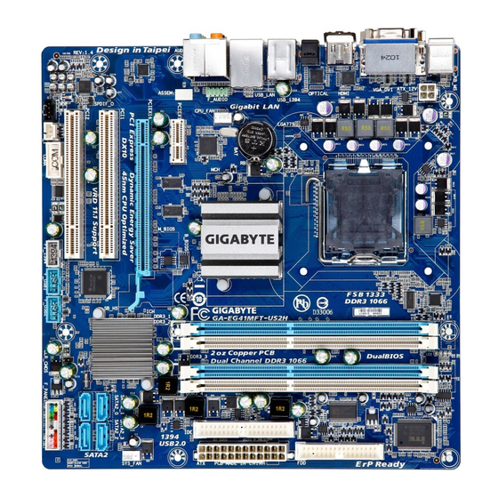
Page 7: Ga-Eg41Mf-Us2H Motherboard Layout
GA-EG41MF-US2H Motherboard Layout PHASE LED KB_MS LGA775 ATX_12V Level Shifter Level Shifter OPTICAL USB_1394 BATTERY Intel ® CPU_FAN AUDIO F_AUDIO PCIE_1 B_BIOS M_BIOS PCIE_16 RTL8111C/D SYS_FAN PCI1 Intel ICH7 ® SATA2_1 SATA2_3 TSB43AB23 SPDIF_O PCI2 SATA2_0 SATA2_2 CODEC CLR_CMOS COMA... -
Page 8: Block Diagram
Block Diagram PCIe CLK LGA775 CPU CLK+/- 1 PCI Express x16 (Note) (100 MHz) Processor (333/266/200 MHz) Host HDMI DVI-D Interface DDR2 800/667 MHz Switch Switch Dual Channel Memory PCI Express x16 Intel ® GMCH CLK D-Sub (333/266/200 MHz) 1 PCI Express x1 Dual BIOS RJ45 RTL8111C/D... -
Page 9: Chapter 1 Hardware Installation
Chapter 1 Hardware Installation Installation Precautions The motherboard contains numerous delicate electronic circuits and components which can become damaged as a result of electrostatic discharge (ESD). Prior to installation, carefully read the user's manual and follow these procedures: Prior to installation, do not remove or break motherboard S/N (Serial Number) sticker or •... -
Page 10: Product Specifications
USB headers) IEEE 1394a T.I. TSB43AB23 chip Up to 2 IEEE 1394a ports (1 on the back panel, 1 via the IEEE 1394a bracket connected to the internal IEEE 1394a header) GA-EG41MF-US2H Motherboard - 10 -... - Page 11 Internal Connectors 1 x 24-pin ATX main power connector 1 x 4-pin ATX 12V power connector 1 x floppy disk drive connector 1 x IDE connector 4 x SATA 3Gb/s connectors 1 x CPU fan header ...
- Page 12 When the PCI Express x16 slot is in use, the HDMI and the DVI-D ports become unavailable. (Note 5) Whether the CPU/System fan speed control function is supported will depend on the CPU/ System cooler you install. (Note 6) Available functions in EasyTune may differ by motherboard model. GA-EG41MF-US2H Motherboard - 12 -...
-
Page 13: Installing The Cpu And Cpu Cooler
Installing the CPU and CPU Cooler Read the following guidelines before you begin to install the CPU: • Make sure that the motherboard supports the CPU. (Go to GIGABYTE's website for the latest CPU support list.) • Always turn off the computer and unplug the power cord from the power outlet before installing the CPU to prevent hardware damage. - Page 14 CPU notches with the socket alignment keys) and gently insert the CPU into position. Step 5: Once the CPU is properly inserted, replace the load plate and push the CPU socket lever back into its locked position. GA-EG41MF-US2H Motherboard - 14 -...
-
Page 15: Installing The Cpu Cooler
1-3-2 Installing the CPU Cooler Follow the steps below to correctly install the CPU cooler on the motherboard. (The following procedure uses Intel boxed cooler as the example cooler.) ® Male Push Pin Direction of the Arrow Sign on the Male The Top Push Pin of Female... -
Page 16: Installing The Memory
Flex Memory Mode will appear during the POST. Intel Flex Memory ® Technology offers greater flexibility to upgrade by allowing different memory sizes to be populated and remain in Dual Channel mode/performance. GA-EG41MF-US2H Motherboard - 16 -... -
Page 17: Installing A Memory
1-4-2 Installing a Memory Before installing a memory module , make sure to turn off the computer and unplug the power cord from the power outlet to prevent damage to the memory module. DDR2 DIMMs are not compatible to DDR DIMMs. Be sure to install DDR2 DIMMs on this motherboard. -
Page 18: Installing An Expansion Card
Make sure the card is securely seated in the slot and does not rock. • Removing the Card: Gently push back on the lever on the slot and then lift the card straight out from the slot. GA-EG41MF-US2H Motherboard - 18 -... -
Page 19: Back Panel Connectors
Back Panel Connectors (Note 1) (Note 2) (Note 2) PS/2 Keyboard and PS/2 Mouse Port Use the upper port (green) to connect a PS/2 mouse and the lower port (purple) to connect a PS/2 keyboard. D-Sub Port The D-Sub port supports a 15-pin D-Sub connector. Connect a monitor that supports D-Sub connection to this port. -
Page 20: Usb Port
Activity LED: State Description State Description Orange 1 Gbps data rate Blinking Data transmission or receiving is occurring Green 100 Mbps data rate No data transmission or receiving is occurring 10 Mbps data rate LAN Port GA-EG41MF-US2H Motherboard - 20 -... - Page 21 Center/Subwoofer Speaker Out Jack (Orange) Use this audio jack to connect center/subwoofer speakers in a 5.1/7.1-channel audio configuration. Rear Speaker Out Jack (Black) Use this audio jack to connect rear speakers in a 4/5.1/7.1-channel audio configuration. Side Speaker Out Jack (Gray) Use this audio jack to connect side speakers in a 7.1-channel audio configuration.
-
Page 22: Internal Connectors
• After installing the device and before turning on the computer, make sure the device cable has been securely attached to the connector on the motherboard. GA-EG41MF-US2H Motherboard - 22 -... - Page 23 1/2) ATX_12V/ATX (2x2 12V Power Connector and 2x12 Main Power Connector) With the use of the power connector, the power supply can supply enough stable power to all the components on the motherboard. Before connecting the power connector, first make sure the power supply is turned off and all devices are properly installed.
- Page 24 360 KB, 720 KB, 1.2 MB, 1.44 MB, and 2.88 MB. Before connecting a floppy disk drive, be sure to locate pin 1 of the connector and the floppy disk drive cable. The pin 1 of the cable is typically designated by a stripe of different color. GA-EG41MF-US2H Motherboard - 24 -...
- Page 25 6) IDE (IDE Connector) The IDE connector supports up to two IDE devices such as hard drives and optical drives. Before attaching the IDE cable, locate the foolproof groove on the connector. If you wish to connect two IDE devices, remember to set the jumpers and the cabling according to the role of the IDE devices (for example, master or slave).
-
Page 26: System Power Led Header
• When installing the battery, note the orientation of the positive side (+) and the negative side (-) of the battery (the positive side should face up). • Used batteries must be handled in accordance with local environmental regulations. GA-EG41MF-US2H Motherboard - 26 -... - Page 27 10) F_PANEL (Front Panel Header) Connect the power switch, reset switch, speaker and system status indicator on the chassis front panel to this header according to the pin assignments below. Note the positive and negative pins before connecting the cables. Reset Hard Drive Switch...
-
Page 28: Cd In Connector
12) CD_IN (CD In Connector, Black) You may connect the audio cable that came with your optical drive to the header. Pin No. Definition CD-L CD-R GA-EG41MF-US2H Motherboard - 28 -... -
Page 29: S/Pdif Out Header
13) SPDIF_I (S/PDIF In Header, Red) This header supports digital S/PDIF In and can connect to an audio device that supports digital audio out via an optional S/PDIF In cable. For purchasing the optional S/PDIF In cable, please contact the local dealer. Pin No. -
Page 30: Usb/Ieee 1394A Headers
• To connect an IEEE 1394a device, attach one end of the device cable to your computer and then attach the other end of the cable to the IEEE 1394a device. Ensure that the cable is securely connected. GA-EG41MF-US2H Motherboard - 30 -... - Page 31 17) COMA (Serial Port Header, White) The COMA header can provide one serial port via an optional COM port cable. For purchasing the optional COM port cable, please contact the local dealer. Pin No. Definition NDCD- NSIN NSOUT NDTR- NDSR- NRTS- NCTS- NRI-...
-
Page 32: Phase Led
The number of lighted LEDs indicates the CPU loading. The higher the CPU loading, the more the number of lighted LEDs. To enable the Phase LED display function, please first enable Dynamic Energy Saver Advanced. Refer to Chapter 4, "Dynamic Energy Saver Advanced," for more details. GA-EG41MF-US2H Motherboard - 32 -... -
Page 33: Chapter 2 Bios Setup
Chapter 2 BIOS Setup BIOS (Basic Input and Output System) records hardware parameters of the system in the CMOS on the motherboard. Its major functions include conducting the Power-On Self-Test (POST) during system startup, saving system parameters and loading operating system, etc. BIOS includes a BIOS Setup program that allows the user to modify basic system configuration settings or to activate certain system features. -
Page 34: Startup Screen
BIOS Setup settings. You can access Boot Menu again to change the first boot device setting as needed. <End>: Qflash Press the <End> key to access the Q-Flash utility directly without having to enter BIOS Setup first. GA-EG41MF-US2H Motherboard - 34 -... -
Page 35: The Main Menu
The Main Menu Once you enter the BIOS Setup program, the Main Menu (as shown below) appears on the screen. Use arrow keys to move among the items and press <Enter> to accept or enter a sub-menu. (Sample BIOS Version: F1a) CMOS Setup Utility-Copyright (C) 1984-2009 Award Software ... - Page 36 Exit Without Saving Abandon all changes and the previous settings remain in effect. Pressing <Y> to the confirmation message will exit BIOS Setup. (Pressing <Esc> can also carry out this task.) GA-EG41MF-US2H Motherboard - 36 -...
-
Page 37: Mb Intelligent Tweaker(M.i.t.)
MB Intelligent Tweaker(M.I.T.) CMOS Setup Utility-Copyright (C) 1984-2009 Award Software MB Intelligent Tweaker(M.I.T.) Robust Graphics Booster [Auto] Item Help (Note) CPU Clock Ratio [7X] Menu Level (Note) Fine CPU Clock Ratio [+0.5] CPU Frequency 3.73GHz(266x14) ******** Clock Chip Control ******** >>>>>... - Page 38 Allows you to manually set the PCIe clock frequency. The adjustable range is from 90 MHz to 150 MHz. Auto sets the PCIe clock frequency to standard 100 MHz. (Default: Auto) (Note) This item appears only if you install a CPU that supports this feature. GA-EG41MF-US2H Motherboard - 38 -...
- Page 39 >>>>> Advanced Clock Control Advanced Clock Control CMOS Setup Utility-Copyright (C) 1984-2009 Award Software Advanced Clock Control CPU Clock Drive [800mV] Item Help PCI Express Clock Drive [800mV] Menu Level CPU Clock Skew [0ps] MCH Clock Skew [0ps] : Move Enter: Select +/-/PU/PD: Value F10: Save...
- Page 40 Channel B Timing Settings [Press Enter] Channel B Driving Settings [Press Enter] : Move Enter: Select +/-/PU/PD: Value F10: Save ESC: Exit F1: General Help F5: Previous Values F6: Fail-Safe Defaults F7: Optimized Defaults GA-EG41MF-US2H Motherboard - 40 -...
- Page 41 Advanced Timing Control ******** ******** tRRD Options are: Auto (default), 1~15. tWTR Options are: Auto (default), 1~31. Options are: Auto (default), 1~31. tRFC Options are: Auto (default), 1~255. tRTP Options are: Auto (default), 1~15. Command Rate(CMD) Options are: Auto (default), 1~3. >>>>>...
- Page 42 F6: Fail-Safe Defaults F7: Optimized Defaults Driving Strength Profile Options are: Auto (default), 667MHz, 800MHz, 1066MHz, OC-1200, OC-1333. Data Driving Pull-Up Level Options are: Auto (default), +8~-7. Cmd Driving Pull-Up Level Options are: Auto (default), +8~-7. GA-EG41MF-US2H Motherboard - 42 -...
- Page 43 Ctrl Driving Pull-Up Level Options are: Auto (default), +8~-7. Clk Driving Pull-Up Level Options are: Auto (default), +8~-7. Data Driving Pull-Down Level Options are: Auto (default), +8~-7. Cmd Driving Pull-Down Level Options are: Auto (default), +8~-7. Ctrl Driving Pull-Down Level Options are: Auto (default), +8~-7.
-
Page 44: Standard Cmos Features
If no IDE/SATA devices are used, set this item to None so the system will skip the detection of the device during the POST for faster system startup. Access Mode Sets the hard drive access mode. Options are: Auto (default), Large. GA-EG41MF-US2H Motherboard - 44 -... - Page 45 The following fields display your hard drive specifications. If you wish to enter the parameters manually, refer to the information on the hard drive. Capacity Approximate capacity of the currently installed hard drive. Cylinder Number of cylinders. Head Number of heads. Precomp Write precompensation cylinder.
-
Page 46: Advanced Bios Features
(Default: Enabled) (Note) This item is present only if you install a CPU that supports this feature. For more information about Intel CPUs' unique features, please visit Intel's website. GA-EG41MF-US2H Motherboard - 46 -... - Page 47 CPU Multi-Threading (Note) Allows you to determine whether to enable all CPU cores and multi-threading function when using an Intel CPU that supports multi-core technology. This feature only works for operating systems ® that support multi-processor mode. Enabled Enables all CPU cores and multi-threading capability. (Default) Disabled Enables only one CPU core.
-
Page 48: Advanced Chipset Features
Reserves 96 MB of system memory during boot. This memory is not seen by the operating system and not available to any user application. Aero (DWM) in Windows Vista will always be turned off in this mode. GA-EG41MF-US2H Motherboard - 48 -... - Page 49 PAVP Lite Mode This item is configurable only if the PAVP Mode option is set to PAVP Lite Mode. Options are: 32MB (default), 48MB, 64MB, 128MB and 256MB. Paranoid PAVP Mode This item is configurable only if the PAVP Mode option is set to Paranoid PAVP. Options are: (32+96)128MB (default), (48+96)144MB, (64+96)160MB, (128+96)224MB and (256+96)352MB.
-
Page 50: Integrated Peripherals
This value is dependent on the On-Chip SATA Mode and PATA IDE Set to settings. When PATA IDE Set to is configured to Ch. 0 Master/Slave, this option will be automatically set to Ch. 1 Master/Slave. GA-EG41MF-US2H Motherboard - 50 -... - Page 51 Azalia Codec Enables or disables the onboard audio function. (Default: Auto) If you wish to install a 3rd party add-in audio card instead of using the onboard audio, set this item to Disabled. Onboard H/W 1394 Enables or disables the onboard IEEE 1394 function. (Default: Enabled) Onboard H/W LAN Enables or disables the onboard LAN function.
- Page 52 USB Mouse Function Allows USB mouse to be used in MS-DOS. (Default: Disabled) USB Storage Function Determines whether to detect USB storage devices, including USB flash drives and USB hard drives during the POST. (Default: Enabled) GA-EG41MF-US2H Motherboard - 52 -...
-
Page 53: Power Management Setup
Power Management Setup CMOS Setup Utility-Copyright (C) 1984-2009 Award Software Power Management Setup ACPI Suspend Type [S3(STR)] Item Help Soft-Off by PWR-BTTN [Instant-Off] Menu Level PME Event Wake Up [Enabled] Power On by Ring [Enabled] Resume by Alarm [Disabled] x Date (of Month) Alarm Everyday x Time (hh:mm:ss) Alarm 0 : 0 : 0... - Page 54 The system is turned on upon the return of the AC power. Memory The system returns to its last known awake state upon the return of the AC power. (Note) Supported on Windows Vista operating system only. GA-EG41MF-US2H Motherboard - 54 -...
-
Page 55: Pnp/Pci Configurations
PnP/PCI Configurations CMOS Setup Utility-Copyright (C) 1984-2009 Award Software PnP/PCI Configurations PCI1 IRQ Assignment [Auto] Item Help PCI2 IRQ Assignment [Auto] Menu Level : Move Enter: Select +/-/PU/PD: Value F10: Save ESC: Exit F1: General Help F5: Previous Values F6: Fail-Safe Defaults F7: Optimized Defaults PCI1 IRQ Assignment Auto... -
Page 56: Pc Health Status
Enables or disables the CPU fan speed control function. Enabled allows the CPU fan to run at different speed according to the CPU temperature. You can adjust the fan speed with EasyTune based on system requirements. If disabled, CPU fan runs at full speed. (Default: Enabled) GA-EG41MF-US2H Motherboard - 56 -... -
Page 57: Load Fail-Safe Defaults
2-11 Load Fail-Safe Defaults CMOS Setup Utility-Copyright (C) 1984-2009 Award Software MB Intelligent Tweaker(M.I.T.) PC Health Status Standard CMOS Features Load Fail-Safe Defaults Advanced BIOS Features Load Optimized Defaults Advanced Chipset Features Set Supervisor Password ... -
Page 58: Set Supervisor/User Password
BIOS settings but not to make changes. To clear the password, press <Enter> on the password item and when requested for the password, press <Enter> again. The message "PASSWORD DISABLED" will appear, indicating the password has been cancelled. GA-EG41MF-US2H Motherboard - 58 -... -
Page 59: Save & Exit Setup
2-14 Save & Exit Setup CMOS Setup Utility-Copyright (C) 1984-2009 Award Software MB Intelligent Tweaker(M.I.T.) PC Health Status Standard CMOS Features Load Fail-Safe Defaults Advanced BIOS Features Load Optimized Defaults Save to CMOS and EXIT (Y/N)? Y ... - Page 60 GA-EG41MF-US2H Motherboard - 60 -...
-
Page 61: Chapter 3 Drivers Installation
Chapter 3 Drivers Installation • Before installing the drivers, first install the operating system. • After installing the operating system, insert the motherboard driver disk into your optical drive. The driver Autorun screen is automatically displayed which looks like that shown in the screen shot below. -
Page 62: Application Software
This page displays all the utilities and applications that GIGABYTE develops and some free software. You can click the Install button on the right of an item to install it. Technical Manuals This page provides GIGABYTE's application guides, content descriptions for this driver disk, and the motherboard manuals. GA-EG41MF-US2H Motherboard - 62 -... -
Page 63: Contact
Contact For the detailed contact information of the GIGABYTE Taiwan headquarter or worldwide branch offices, click the URL on this page to link to the GIGABYTE website. System This page provides the basic system information. - 63 - Drivers Installation... -
Page 64: Download Center
Download Center To update the BIOS, drivers, or applications, click the Download Center button to link to the GIGABYTE website. The latest version of the BIOS, drivers, or applications will be displayed. GA-EG41MF-US2H Motherboard - 64 -... -
Page 65: Chapter 4 Unique Features
Chapter 4 Unique Features Xpress Recovery2 Xpress Recovery2 is a utility that allows you to quickly compress and back up your system data and perform restoration of it. Supporting NTFS, FAT32, and FAT16 file systems, Xpress Recovery2 can back up data on PATA and SATA hard drives and restore it. Before You Begin: •... - Page 66 Xpress Recovery2 will automatically create a new partition to store the backup image file. Step 1: Step 2: Select BACKUP to start backing up your hard When finished, go to Disk Management to drive data. check disk allocation. GA-EG41MF-US2H Motherboard - 66 -...
- Page 67 D. Using the Restore Function in Xpress Recovery2 Select RESTORE to restore the backup to your hard drive in case the system breaks down. The RESTORE option will not be present if no backup is created before. E. Removing the Backup Step 1: Step 2: If you wish to remove the backup file, select...
-
Page 68: Bios Update Utilities
Copyright (C) 1984-2009, Award Software, Inc. EG41MF-US2H F1a <DEL>: BIOS Setup <F9>: XpressRecovery2 <F12>: Boot Menu <End>: Qflash 03/09/2009-G41-ICH7-7A69PG0JC-00 Because BIOS flashing is potentially risky, please do it with caution. Inadequate BIOS flashing may result in system malfunction. GA-EG41MF-US2H Motherboard - 68 -... - Page 69 B. Updating the BIOS When updating the BIOS, choose the location where the BIOS file is saved. The follow procedure assumes that you save the BIOS file to a floppy disk. Step 1: 1. Insert the floppy disk containing the BIOS file into the floppy disk drive. In the main menu of Q-Flash, use the up or down arrow key to select Update BIOS from Drive and press <Enter>.
- Page 70 Load Optimized Defaults Press <Y> to load BIOS defaults Step 6: Select Save & Exit Setup and then press <Y> to save settings to CMOS and exit BIOS Setup. The procedure is complete after the system restarts. GA-EG41MF-US2H Motherboard - 70 -...
-
Page 71: Updating The Bios With The @Bios Utility
4-2-2 Updating the BIOS with the @BIOS Utility A. Before You Begin: 1. In Windows, close all applications and TSR (Terminate and Stay Resident) programs. This helps prevent unexpected failures when performing a BIOS update. 2. During the BIOS update process, ensure the Internet connection is stable and do NOT interrupt the Internet connection (for example, avoid a power loss or switching off the Internet). -
Page 72: Easytune 6
Incorrectly doing overclock/overvoltage may result in damage to the hardware components such as CPU, chipset, and memory and reduce the useful life of these components. Before you do the overclock/overvoltage, make sure that you fully know each function of EasyTune 6, or system instability or other unexpected results may occur. GA-EG41MF-US2H Motherboard - 72 -... -
Page 73: Dynamic Energy Saver Advanced
Dynamic Energy Saver Advanced GIGABYTE Dynamic Energy Saver Advanced is a revolutionary technology that delivers unpar- (Note 1) alleled power savings with a click of the button. Featuring an advanced proprietary hardware and software design, GIGABYTE Dynamic Energy Saver Advanced is able to provide exceptional power savings and enhanced power efficiency without sacrificing computing performance. - Page 74 (Note 4) The total amount of power saved will be recorded until re-activated when only the Dynamic Power Saver is under the enable status, and power savings meter is unable to reset to zero. (Note 5) Dynamic Energy Saver Meter will automatically reset when the total power saving reaches 99999999 Watts. GA-EG41MF-US2H Motherboard - 74 -...
-
Page 75: Q-Share
Q-Share Q-Share is an easy and convenient data sharing tool. After configuring your LAN connection settings and Q-Share, you are able to share your data with computers on the same network, making full use of Internet resources. Directions for using Q-Share After installing Q-Share from the motherboard driver disk, go to Start>All Programs>GIGABYTE>... -
Page 76: Time Repair
• Each storage volume can accommodate 64 shadow copies. When this limit is reached, the oldest shadow copy will be deleted and unable to be restored. Shadow copies are read-only so you cannot edit the contents of a shadow copy. GA-EG41MF-US2H Motherboard - 76 -... -
Page 77: Chapter 5 Appendix
Chapter 5 Appendix Configuring Audio Input and Output 5-1-1 Configuring 2/4/5.1/7.1-Channel Audio The motherboard provides six audio jacks on the back panel which support 2/4/5.1/7.1-channel audio. Center/Subwoofer The picture to the right shows the default audio jack Line In Speaker Out assignments. - Page 78 Click Device advanced settings on the top right cor- ner on the Speaker Configuration tab to open the Device advanced settings dialog box. Select the Mute the rear output device, when a front headphone plugged in check box. Click OK to complete. GA-EG41MF-US2H Motherboard - 78 -...
-
Page 79: Configuring S/Pdif In/Out
5-1-2 Configuring S/PDIF In/Out A. S/PDIF In: The S/PDIF In cable (optional) allows you to input digital audio signals to the computer for audio processing. S/PDIF In Cable Coaxial Optical S/PDIF In S/PDIF In 1. Installing the S/PDIF In Cable: Step 1: Step 2: First, attach the connector at the end of the cable... - Page 80 Connect a S/PDIF coaxial cable or a S/PDIF optical cable (either one) to an external decoder for transmitting the S/PDIF digital audio signals. 2. Configuring S/PDIF Out: On the Digital Output screen, click the Default Format tab and then select the sample rate and bit depth. Click OK to complete. GA-EG41MF-US2H Motherboard - 80 -...
-
Page 81: Configuring Microphone Recording
5-1-3 Configuring Microphone Recording Step 1: After installing the audio driver, the HD Audio Manager icon will appear in the notification area. Double- click the icon to access the HD Audio Manager. Step 2: Connect your microphone to the Mic in jack (pink) on the back panel or the Mic in jack (pink) on the front panel. - Page 82 Step 1: Locate the Volume icon in the notification area and right-click on this icon. Select Recording Devices. Step 2: On the Recording tab, right-click on an empty space and select Show Disabled Devices. GA-EG41MF-US2H Motherboard - 82 -...
-
Page 83: Using The Sound Recorder
Step 3: When the Stereo Mix item appears, right-click on this item and select Enable. Then set it as the default device. Step 4: Now you can access the HD Audio Manager to configure Stereo Mix and use Sound Recorder to record the sound. -
Page 84: Troubleshooting
1 long, 2 short: Monitor or graphics card error 1 long, 3 short: Keyboard error 1 long, 9 short: BIOS ROM error Continuous long beeps: Graphics card not inserted properly Continuous short beeps: Power error GA-EG41MF-US2H Motherboard - 84 -... -
Page 85: Troubleshooting Procedure
5-2-2 Troubleshooting Procedure If you encounter any troubles during system startup, follow the troubleshooting procedure below to solve the problem. START Turn off the power. Remove all peripherals, connecting cables, and power cord etc. Make sure the motherboard does not short-circuit with the chassis Isolate the short circuit. - Page 86 If the procedure above is unable to solve your problem, contact the place of purchase or local dealer for help. Or go to the Support&Downloads\Technical Service Zone page to submit your question. Our customer service staff will reply you as soon as possible. GA-EG41MF-US2H Motherboard - 86 -...
-
Page 87: Regulatory Statements
Regulatory Statements Regulatory Notices This document must not be copied without our written permission, and the contents there of must not be imparted to a third party nor be used for any unauthorized purpose. Contravention will be prosecuted. We believe that the information contained herein was accurate in all respects at the time of printing. GIGABYTE cannot, however, assume any responsibility for errors or omissions in this text. - Page 88 "end of life" products, and generally improve our quality of life by ensuring that potentially hazardous substances are not released into the environment and are disposed of properly. China Restriction of Hazardous Substances Table The following table is supplied in compliance with China's Restriction of Hazardous Substances (China RoHS) requirements: GA-EG41MF-US2H Motherboard - 88 -...
- Page 89 - 89 - Appendix...
- Page 90 GA-EG41MF-US2H Motherboard - 90 -...
- Page 91 - 91 - Appendix...
- Page 92 GA-EG41MF-US2H Motherboard - 92 -...
- Page 93 - 93 - Appendix...
- Page 94 GA-EG41MF-US2H Motherboard - 94 -...
- Page 95 TEL: +86-24-83992901 GIGA-BYTE SINGAPORE PTE. LTD. - Singapore FAX: +86-24-83992909 WEB address : http://www.gigabyte.sg GIGABYTE TECHNOLOGY (INDIA) LIMITED - India Thailand WEB address : http://www.gigabyte.in ...
- Page 96 Russia WEB address : http://www.giga-byte.nl WEB address : http://www.gigabyte.ru GIGABYTE TECHNOLOGY FRANCE - France Poland WEB address : http://www.gigabyte.fr WEB address : http://www.gigabyte.pl...
Need help?
Do you have a question about the GA-EG41MF-US2H and is the answer not in the manual?
Questions and answers