Table of Contents
Advertisement
GARAGE DOOR OPENER
Model 1345BM 1/3HP
For Residential Use Only
Owner's Manual
■
Please read this manual and the enclosed safety materials carefully!
■
Fasten the manual near the garage door after installation.
■
The door WILL NOT CLOSE unless the Protector System
properly aligned.
■
Periodic checks of the opener are required to ensure safe operation.
■
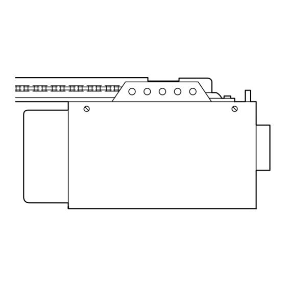
The model number label is located on the front panel of your opener.
BuildMark™ Garage Doors
1101 E. River Road
Dixon, Illinois 61021
®
is connected and
Advertisement
Table of Contents

Related Manuals for BuildMark 1345BM 1/3HP


Summary of Contents for BuildMark 1345BM 1/3HP
- Page 1 BuildMark™ Garage Doors 1101 E. River Road Dixon, Illinois 61021 GARAGE DOOR OPENER Model 1345BM 1/3HP For Residential Use Only Owner’s Manual ■ Please read this manual and the enclosed safety materials carefully! ■ Fasten the manual near the garage door after installation.
-
Page 2: Table Of Contents
TABLE OF CONTENTS Introduction Adjustment 23-25 Safety symbol and signal word review......2 Adjust the travel limits ..........23 Preparing your garage door ........3 Adjust the force ............24 Tools needed ...............3 Test the safety reversal system.........25 Planning ..............4 Test the Protector System ®... -
Page 3: Preparing Your Garage Door
Preparing your garage door WARNING Before you begin: To prevent possible SERIOUS INJURY OR DEATH: • Disable locks. • ALWAYS call a trained door systems technician if CAUTION • Remove any ropes connected to garage door. garage door binds, sticks, or is out of balance. An unbalanced garage door may not reverse when •... -
Page 4: Planning
Planning Identify the type and height of your garage door. Survey your garage area to see if any of the conditions below apply to your installation. Additional materials may be required. You may find it helpful to refer back to this page and the accompanying illustrations as you proceed with the installation of your opener. -
Page 5: Carton Inventory
Parts may be stuck in the foam. below. Accessories will depend on the model Hardware for installation is also listed below. Remote Control Sprocket Cover Visor Clip Door Control Button BuildMark™ SECURITY✚ ® Single-Button Remote Control (1) Single-Button Remote Control (1) Styrofoam Chain... -
Page 6: Assembly
WARNING CAUTION ASSEMBLY STEP 1 Attach the Rail to the Motor Unit To avoid SERIOUS damage to garage door opener, use ONLY those bolts/fasteners mounted in the top of To avoid installation difficulties, do not run the the opener. garage door opener until instructed to do so. •... -
Page 7: Tighten The Chain
Figure 1 ASSEMBLY STEP 3 Lock Tighten the Chain Washer Outer Nut Inner Nut To Tighten Outer Nut • Spin the inner nut and lock washer down the trolley threaded shaft, away from the trolley. To Tighten Inner Nut • To tighten the chain, turn outer nut in the direction shown (Figure 1). -
Page 8: Determine The Header Bracket Location
Unfinished INSTALLATION STEP 1 OPTIONAL Ceiling CEILING Determine the Header Bracket MOUNT Location HEADER BRACKET Header Wall WARNING WARNING Vertical Centerline of Garage Door To prevent possible SERIOUS INJURY or DEATH: • Header bracket MUST be RIGIDLY fastened to Structural CAUTION WARNING Supports... -
Page 9: Install The Header Bracket
INSTALLATION STEP 2 Install the Header Bracket Wall Mounting Holes You can attach the header bracket either to the wall above the garage door, or to the ceiling. Follow the CEILING MOUNT ONLY The nail hole is for instructions which will work best for your particular positioning only. -
Page 10: Attach The Rail To The Header Bracket
INSTALLATION STEP 3 Attach the Rail to the Header Bracket • Position the opener on the garage floor below the header bracket. Use packing material as a protective base. NOTE: If the door spring is in the way you’ll need help. Have someone hold the opener securely on a temporary support to allow the rail to clear the spring. -
Page 11: Position The Opener
WARNING CAUTION INSTALLATION STEP 4 Position the Opener To prevent damage to garage door, rest garage door opener rail on 2x4 placed on top section of door. Follow instructions which apply to your door type as illustrated. SECTIONAL DOOR OR ONE-PIECE DOOR WITH TRACK A 2x4 laid flat is convenient for setting an ideal door-to-rail distance. -
Page 12: Hang The Opener
WARNING INSTALLATION STEP 5 Hang the Opener To avoid possible SERIOUS INJURY from a falling garage door opener, fasten it SECURELY to structural CAUTION Three representative installations are shown. Yours supports of the garage. Concrete anchors MUST be used may be different. Hanging brackets should be angled if installing any brackets into masonry. -
Page 13: Install The Door Control
WARNING WARNING CAUTION WARNING INSTALLATION STEP 6 Install the Door Control To prevent possible SERIOUS INJURY or DEATH from electrocution: Locate the door control within sight of the door at a • Be sure power is not connected BEFORE installing door minimum height of 5 feet (1.5 m) where small control. -
Page 14: Install The Light
WARNING INSTALLATION STEP 7 CAUTION Install the Light To prevent possible OVERHEATING of the endpanel or light socket, INSTALL THE LIGHT • DO NOT use short neck or specialty light bulbs. • Install a 75 watt maximum light bulb in the socket. •... -
Page 15: Electrical Requirements
WARNING WARNING INSTALLATION STEP 9 Electrical Requirements To prevent possible SERIOUS INJURY or DEATH from electrocution or fire: CAUTION WARNING To avoid installation difficulties, do not run the • Be sure power is not connected to the opener, and opener at this time. disconnect power to circuit BEFORE removing cover to To reduce the risk of electric shock, your garage door establish permanent wiring connection. -
Page 16: Install The Protector System
WARNING INSTALLATION STEP 10 Install The Protector System ® Be sure power is not connected to the garage door opener BEFORE installing the safety reversing sensor. CAUTION The safety reversing sensor must be connected To prevent SERIOUS INJURY or DEATH from a closing and aligned correctly before the garage door garage door: opener will move in the down direction. - Page 17 INSTALLING THE BRACKETS Be sure power to the opener is disconnected. Figure 1 DOOR TRACK MOUNT (RIGHT SIDE) Install and align the brackets so the sensors will face each other across the garage door, with the beam no higher than 6" (15 cm) above the floor. They may be Door installed in one of three ways, as follows.
- Page 18 MOUNTING AND WIRING THE SAFETY SENSORS Figure 5 • Slide a 1/4"-20x1/2" carriage bolt head into the slot Wing Nut 1/4"-20 on each sensor. Use wing nuts to fasten sensors to brackets, with lenses pointing toward each other across the door. Be sure the lens is not obstructed by a bracket extension (Figure 5).
-
Page 19: Fasten The Door Bracket
WARNING CAUTION INSTALLATION STEP 11 Fasten the Door Bracket Fiberglass, aluminum or lightweight steel garage doors WILL REQUIRE reinforcement BEFORE installation of Follow instructions which apply to your door type as door bracket. Contact your door manufacturer for illustrated below or on the following page. reinforcement kit. - Page 20 ONE-PIECE DOORS Please read and comply with the warnings and reinforcement instructions on the previous page. They apply to one-piece doors also. • Center the door bracket on the top of the door, in line with the header bracket as shown. Mark either the left and right, or the top and bottom holes.
-
Page 21: Connect Door Arm To Trolley
INSTALLATION STEP 12 Inner Trolley Connect Door Arm to Trolley Outer Trolley Follow instructions which apply to your door type as illustrated below and on the following page. SECTIONAL DOORS ONLY Clevis Pin 5/16"x1" Ring • Make sure garage door is fully closed. Pull the Fastener emergency release handle to disconnect the outer trolley from the inner trolley. -
Page 22: Connect The Door Arm To The Trolley
ALL ONE-PIECE DOORS Door Bracket Ring 1. Assemble the door arm, Figure 4: Fastener Nuts • Fasten the straight and curved door arm sections Lock 5/16"-18 together to the longest possible length (with a 2 Washers 5/16" or 3 hole overlap). Clevis Pin Straight 5/16"x1-1/4"... -
Page 23: Adjust The Travel Limits
WARNING ADJUSTMENT STEP 1 Adjust the UP and DOWN Travel Without a properly installed safety reversal system, Limits persons (particularly small children) could be CAUTION SERIOUSLY INJURED or KILLED by a closing garage Limit adjustment settings regulate the points at which door. -
Page 24: Adjustment
WARNING ADJUSTMENT STEP 2 Adjust the Force Without a properly installed safety reversal system, persons (particularly small children) could be CAUTION Force adjustment controls are located on the back SERIOUSLY INJURED or KILLED by a closing garage panel of the motor unit. Force adjustment settings door. -
Page 25: Test The Safety Reversal System
WARNING ADJUSTMENT STEP 3 Test the Safety Reversal System Without a properly installed safety reversal system, persons (particularly small children) could be CAUTION SERIOUSLY INJURED or KILLED by a closing garage TEST door. • With the door fully open, place a 1-1/2" (3.8 cm) •... -
Page 26: Operation
WARNING OPERATION IMPORTANT SAFETY INSTRUCTIONS WARNING To reduce the risk of SEVERE INJURY or DEATH: 1. READ AND FOLLOW ALL WARNINGS AND 8. NEVER use handle to pull garage door open or closed. INSTRUCTIONS. If rope knot becomes untied, you could fall. 2. -
Page 27: Using The Wall-Mounted Door Control
Using the Wall-Mounted To Open the Door Manually Door Control WARNING Press the button to open or close the door. Press again to reverse the To prevent possible SERIOUS INJURY or DEATH from a door during the closing cycle or to falling garage door: CAUTION stop the door while it's opening. -
Page 28: Care Of Your Garage Door Opener
THE REMOTE CONTROL BATTERY CARE OF YOUR OPENER WARNING LIMIT AND FORCE ADJUSTMENTS: Weather conditions may To prevent possible SERIOUS INJURY or DEATH: FORCE CONTROLS cause some minor changes • NEVER allow small children near batteries. in door operation requiring CAUTION •... -
Page 29: Having A Problem
HAVING A PROBLEM? Bell Wire 1. My door will not close and the light bulbs blink on my motor unit: The safety reversing sensor must be connected and aligned correctly before the garage door opener will move in the down direction. -
Page 30: Diagnostic Chart
Bell Wire Diagnostics Located On Installed Motor Unit Safety Sensor "Learn" Button Your garage door opener is programmed with LED or self-diagnostic capabilities. The “Learn” button/diagnostic Diagnostic Safety Sensor LED will flash a number of times then pause signifying it has found a potential issue. -
Page 31: Programming
PROGRAMMING NOTICE: If this garage door opener is operated with a non-rolling code transmitter, the technical AFETY IGNAL™ measure in the receiver of the garage door opener, which provides security against code-theft devices, will be circumvented. The owner of the copyright in the garage door opener does not authorize the purchaser or supplier of the non-rolling code transmitter to circumvent that technical measure. -
Page 32: To Add, Reprogram Or Change A Keyless Entry Pin
To Add, Reprogram or Change a Keyless Entry PIN NOTE: Your new Keyless Entry must be programmed to operate your garage door opener. USING THE “LEARN” BUTTON To change an existing, known PIN If the existing PIN is known, it may be changed by one person without using a ladder. -
Page 33: Repair Parts
REPAIR PARTS Rail Assembly Parts PART DESCRIPTION 4A1008 Master link kit 41A4813 Chain pulley bracket 41A3489 Complete trolley assembly 1707LM One-piece rail 41D3484 Full chain assembly 83A11-2 Rail grease Installation Parts KEY PART DESCRIPTION 41A4166 Door control button 371BM Single-button remote control 10A20 3V2032 Lithium battery 29B137... -
Page 34: Motor Unit Assembly Parts
Motor Unit Assembly Parts LIMIT SWITCH ASSY. (Down) Contact Brown Wire Grey Wire Drive Gear Center Limit (Up) Yellow Contact Contact Wire KEY PART KEY PART NO. NO. DESCRIPTION NO. NO. DESCRIPTION 31D380 Sprocket cover 41A3583-15 Cover 41C4220A Gear and sprocket assy. Complete 41A2818 Helical gear &... -
Page 35: Accessories
ACCESSORIES BuildMark Single-Button ™ 371BM 1702LM Outside Quick Release: Remote Control: Required for a garage with NO Includes visor clip. access door. 59LM Outside Keylock: 372RGD ™ 2-Button AFETY IGNAL Remote Control: Opens the garage door Includes visor clip. automatically from outside when remote control is not handy. -
Page 36: Repair Parts And Service
6020 S. Country Club Road Tucson, Arizona 85706 For professional installation, parts and service, contact your local BUILDMARK™ GARAGE DOORS SERVICE INFORMATION TOLL FREE NUMBER: distributor. Look for him in the Yellow Pages, or call our service number for a list of dealers in your area.